Feedback Strategy for Closed-loop Inspection Based on STEP-NC

The dimensional inspection is currently consolidated as an important tool in the improvement of manufacturing processes. The demands of quality and the requirement of parts with complex specifications propose new challenges, such as the incorporation of integration and interoperability concepts in measurement operations. An important issue still unresolved in the inspection process is the dynamic management of information that requires solutions that are at the technological forefront and contextualized within the requirements of Industry 4.0. In this perspective, the implementation of a closed-loop inspection supports the measurement requirements for different manufacturing processes and enables the application for different purposes. The feedback strategy proposed in this article proposes an alternative as a solution to integrate the inspection results of a part within a digital manufacturing chain based on STEP-NC (STandard for the Exchange of Product model data - Numerical Control). The mechanisms for acquisition, processing, and analysis of information, and the control architecture that complement the feedback strategy is exposed.

Recommended
More Related Content
What's hot
What's hot (20)
Similar to Feedback Strategy for Closed-loop Inspection Based on STEP-NC
Similar to Feedback Strategy for Closed-loop Inspection Based on STEP-NC (20)
Recently uploaded
Recently uploaded (20)
Feedback Strategy for Closed-loop Inspection Based on STEP-NC
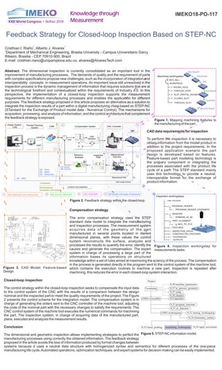
- 1. Feedback Strategy for Closed-loop Inspection Based on STEP-NC Hole Round Open Slot Round Closed Slot ROUND_HOLE WORKPIECE THROUGH_STEP SLOT_PARTIAL_ROUND CLOSED_SLOT THROUGH_SLOT MCS_MILL Machining workingsteps Step Raw Material Hole Round . Abstract. The dimensional inspection is currently consolidated as an important tool in the improvement of manufacturing processes. The demands of quality and the requirement of parts with complex specifications propose new challenges, such as the incorporation of integration and interoperability concepts in measurement operations. An important issue still unresolved in the inspection process is the dynamic management of information that requires solutions that are at the technological forefront and contextualized within the requirements of Industry 4.0. In this perspective, the implementation of a closed-loop inspection supports the measurement requirements for different manufacturing processes and enables the application for different purposes. The feedback strategy proposed in this article proposes an alternative as a solution to integrate the inspection results of a part within a digital manufacturing chain based on STEP-NC (STandard for the Exchange of Product model data - Numerical Control). The mechanisms for acquisition, processing, and analysis of information, and the control architecture that complement the feedback strategy is exposed. Design System CAD Process Planning System CAPP CAIP + - Compensation SystemCAM + + CNC Controller Closed-Loop Inspection E Data Validation + - 1 2 3 4 QIF - Plans QIF - Rules QIF - Resources QIF - MBD Inspection Data Measurement Plan CAD model nominal QIF-Results QIF-Statistics Measurement Execution Tolerance Analyses error ISO 10303-203, 214, 219 and 2421 Comparator Nominal/actual comparison and analysis SENSORS PART_ALIGNMENT MCS_TO_PCS FEATURES OUTPUTS SPM600M_A0_B0 INSPECTION_PATHS CONSTRUCTED_FEATURES TOLERANCES PROGRAM_HEADER CMM_PROGRAM Inspection workingsteps PROGRAM_HEADER_STATEMENT Closed Slot Chamfer face Through slotCircular Through Hole Cylindrical Face Through step Length Width Height 1 4 X 30 + - 0.25 0.25 140 60 200 280 150 0.25 30 8 30 220 44 4 X 44 1000.25 0.08 M A B C 0.25 M A B 0.05 0.08 A B A B 50 280 180 5 X 45°5 X 45° 500.25 250.25 300.25 200.25 150.25 C 2000.05 60 50 20 0.25 30 0.25 15 0.25 30 0.25 0.08 C QIF and ISO 10303-2382 ISO 10303-2383 4 CAD data requirements for inspection To perform the inspection it is necessary to obtain information from the model product in addition to the project requirements. In the proposed application scenario the part design is developed based on features. Feature-based part modeling technology is the primary component in integrating the processes associated with the product life cycle of a part. The STEP standard mainly uses this technology to provide a neutral, interoperable format for the exchange of product information. Compensation strategy The error compensation strategy uses the STEP standard data model to integrate the manufacturing and inspection processes. The measurement system acquires data of the geometry of the part manufactured in several points located in dierent dimensional planes, with these values the control system reconstructs the surface, analyzes and processes the results to quantify the error, identify the causes and generate the compensation. The expert system in charge of processing a large part of the information bases its operations on structured knowledge within a set of rules aimed at maximizing the eciency of the process. The compensation in the process is generated directly in the program sent to the control system of the machine tool, which contains the execution routines to machine a new part. Inspection is repeated after machining, this reduces the error in each closed-loop system interaction. Closed-loop inspection The control strategy within the closed-loop inspection seeks to compensate the input data to the control system of the CNC with the results of a comparison between the design nominal and the inspected part to meet the quality requirements of the project. The Figure 2 presents the control scheme for the integration model. The compensation system is in charge of generating the orders sent to the CNC controller of the machine tool, adjusting the code of the nominal part with the necessary changes to satisfy the requirements. The CNC control system of the machine tool executes the numerical commands for machining the part. The inspection system, in charge of acquiring data of the manufactured part, plans, executes and analyzes the measurement results. Conclusion The dimensional and geometric inspection allows implementing strategies to perfect the manufacturing processes using correctly the obtained information. The feedback strategy proposed in the article avoids the loss of information produced by format changes between systems because it uses a neutral data structure with homogenized syntax and semantics for diferent processes of the one-piece manufacturing life cycle.Automated operations, optimization techniques, and expert systems for decision-making can be easily implemented. 1 1 Cristhian I. Riaño , Alberto J. Alvares 1 Department of Mechanical Engineering, Braslia University - Campus Universitario Darcy Ribeiro, Brasilia - CEP 70910-900, Brazil E-mail: cristhian.riano@unipamplona.edu.co, alvares@AlvaresTech.com Figure 2. Feedback strategy within the closed-loop. Figure 3. CAD Model: Feature-based Design. Figure 1. Mapping machining features to the manufacturing of the part. QIF(Quality Information Framework) Figure 4. Inspection workingstep for measurements tasks. Part IMEKO18-PO-117 Project *workplan (ABS) executable N,50 machine_parameters N,57 in_process_geometry N,47 setup N,58 channel N,9 identifier N,55 program_structure N,51 nc_function (ABS) workingstep N,52 turning_workingstep N,28 elementary_surface N,53 touch_probing N,59 rapid_movementmachining_workingstep Figure 5. STEP-NC information model.