SlideShare a Scribd company logo
1 of 136
Download to read offline
Super Solution
Susol VCB
leads to Susol legend!
eng.lsis.biz
Vacuum Circuit Breakers
www.dienhathe.xyz
www.dienhathe.vn
2II
Susol VCB
lead to Susol legend!
Susol VCB is full line-up new VCB which has the high
interrupting capacity, large current(~50kA, ~4000A), and
maximized compatibility with existing products through the
dual phases and compact sized models.
● External structure 26
● Basic features and interrupting operation 28
● Standards and certification 31
● Types and ordering information 32
● Ratings 38
● Accessories 44
● Control circuit diagrams 76
● Dimensions 80
● Side-Mount Type VCB 126
● Technical data 128
Contents
www.dienhathe.xyz
www.dienhathe.vn
II3
www.dienhathe.xyz
www.dienhathe.vn
4II
Vacuum Circuit Breaker, VCB is installed in the medium voltage distribution
lines to protect life and load equipment. In case of accidents such as over
current, short circuit and ground fault current, VCB works by interrupting the
circuit through the inner Vacuum Interrupter which is acted by signal from the
outside separate relay.
LSIS' Super Solution, Susol VCB responds.
- customer needs for the breakers with high interrupting capacity and large
current due to the integration and increase of the load capacity.
- worldwide trend of diversification in the medium voltage distribution lines.
- increase of the reliability for the temperature characteristics of circuit breakers.
Premium-type products to improve convenience and reliability of medium
voltage switchgear configuration.
- full line-up modeling to the high interrupting capacity and large current.
- main structure with high reliability application.
- a variety of accessories and ability to maximize.
Suitable for use as the main circuit breaker to protect key installations in the
places such as device industry, power plants, high-rise buildings, large ships.
www.dienhathe.xyz
www.dienhathe.vn
II5
▶ Main circuit structure with high reliability.
�Maximizing the durability and reliability of the main circuit contactors
(Stego Tulip contactor).
�Strong structure for the temperature rise (Natural cooling system).
▶ Convenience of switchgear configuration and a variety of
accessories.
�CB compartment structure: Metal isolation structures to prevent the
accident spread and ensure safety. And the convenience of switchgear
building is extended by its module style.
�A variety of accessories: UVT, Locking Magnet, Plug Interlock, Key lock,
Temperature Sensor, MOC, TOC, Earthing S/W.
�Maximizing compatibility with existing products through the dualistic
deployment of phases and compact models.
※ Type testing is complete for all models according to latest standard,
IEC62271-100 (2008) [M2, E2 (List1 or 3), C2].
▶ Strengthening of the high interrupting capacity and large
current models and full line-up new VCB models to
high/middle/low.
Voltage Interrupting current Rated current
7.2kV 8/12.5/20/25/31.5/40/50kA 400/630/1250/2000/3150/4000A
12/17.5kV 20/25/31.5/40/50kA 630/1250/2000/3150/4000A
24kV 12.5/25/31.5/40kA 630/1250/2000/2500/3150A
36kV 25/31.5/40kA 1250/2000/3150A
40.5kV 25/31.5kA 1250/2000/3150A
www.dienhathe.xyz
www.dienhathe.vn
6II
Susol VCB series are premium-type products
featuring main structure with high reliability
application and a variety of accessories and ability
to maximize to be suitable for use as the main
circuit breaker to protect key installations in the
places such as device industry, power plants,
high-rise buildings, large ships
Susol VCB Family
Full line‐‐up & Compact
Full line-up new VCB models to the high interrupting
capacity and large current (~ 50kA, ~ 4000A) featuring
maximization of compatibility with existing products
through the dualistic deployment of phases and
compact models
�Rated short-time (for withstand current ): 3sec.
�Rated operating sequence: O-0.3s-CO-15s-CO
�Type test level: M2, E2 (List1), C2
�Electrical and mechanical life: 30,000 operations
�100% Compatibility
- with existing fixed type breakers
- with existing drawout type breakers
�Various cradle: E, F and G type
�A variety of control power
- DC 24~30V, DC 48~60V, DC 110V, DC 125V, DC 220V
- AC 48V, AC 100~130V, AC 220~250V
�A variety of accessories
- Charge switch, UVT, Secondary trip Coil, Current trip coil,
Trip Latch Checking S/W, Position S/W
- Key-lock, Button lock, Button cover, Padlock, UVT, Time Delay
Controller, Lifting hook, CTD
�TEST/SERVICE Automatic Position Indicator
�Standards and certification
- IEC62271-100 (2008) [M2, C2, E2 (List1)]
- Tested in enclosure
- KERI type tested, V-check (KESCO) certification
7.2kV (VL-06)
Ur Isc Ir
(kV) (kA) (A)
7.2 8 400
12.5 630
www.dienhathe.xyz
www.dienhathe.vn
II7
< < Susol VCB Series
Ur Isc Ir
(kV) (kA) (A)
7.2 20 630
1250
2000
25 630
1250
2000
12 20 630
1250
2000
25 630
1250
2000
17.5 20 630
1250
2000
25 630
1250
2000
�Rated short-time (to withstand current ): 3sec. 4sec*
�Rated operating sequence: O-0.3s-CO-15s-CO
�Type test level: M2, E2 (List3), C2
�Electrical and mechanical life: 30,000 operations
�Compatibility with existing Pro-MEC breakers
�Various cradle: E, F, G and H type
�CB Compartment for MCSG available
�A variety of control power
- DC 24~30V, DC 48~60V, DC 110V, DC 125V, DC 220V
- AC 48V, AC 100~130V, AC 220~250V
�A variety of accessories
- VCB part: Charge switch, UVT, Secondary trip coil, Latch checking
switch, Position switch, Locking magnet, Plug interlock, Key lock, Button
cover, Button padlock, Padlock (H type Door interlock), MOC
- Cradle part: MOC (Mechanical Operated Cell switch), TOC (Truck
Operated Cell switch), Temperature sensor, Earthing switch &
accessaries, Door, Door interlock, Door emergency button
- Others: Racking in/out handle, UVT Time delay controller, CTD
(Condensor Trip Device), Temperature module
�TEST/SERVICE Automatic Position Indicator
�Standards and certification
- IEC62271-100 (2008) [M2, C2, E2 (List3)]
- KEMA, KERI type tested, V-check (KESCO) certification
Note ) * Please contact us
7.2/12/17.5kV (VL-06/12/17)
VCB Cradle type
E type
F type
H type
7.2/12/17.5/24/36/40.5kV (VH-06/12/17/24/36/40)
�Rated short-time (to withstand current ): 3sec. 4sec*
�Rated operating sequence: O-0.3s-CO-3min-CO
�Type test level: M2, E2 (List3), C2
�Electrical and mechanical life: 20,000 operations
�Various cradle: K and H type
�CB Compartment for MCSG available
�A variety of control power
- DC 48V, DC 110V, DC 125V, DC 220V
- AC 48V, AC 110V, AC 220V
�A variety of accessories
- VCB part: UVT, Secondary trip coil, Latch checking switch, Position
switch, Locking magnet, Plug interlock, Key lock, Button cover,
Button padlock, Padlock (H type Door interlock), MOC
- Cradle part: MOC (Mechanical Operated Cell switch), TOC (Truck
Operated Cell switch), Temperature sensor, Earthing switch &
accessaries, Door, Door interlock, Door emergency button
- Others: Racking in/out handle, Lifting hook, UVT Time delay
controller, CTD (Condensor Trip Device), Temperature module
�Standards and certification
- IEC62271-100 (2008) [M2, C2, E2 (List3)]
- KEMA, KERI type tested, V-check (KESCO) certification
Note ) * Please contact us
Ur Isc Ir
(kV) (kA) (A)
7.2 50 1250
12 2000
17.5 2500
3150
4000
24 25 2500
31.5 1250
2000
3150
40 1250
2000
3150
36 25 1250
2000
3150
31.5 1250
2000
3150
40 1250
2000
3150
40.5 25 1250
2000
3150
31.5 1250
2000
3150
www.dienhathe.xyz
www.dienhathe.vn
8II
Vacuum Interrupter, VI
The vacuum rate within the VI is very high
(approximately 5x10⁻⁵
Torr) and the spacing
between fixed contact and movable contact
is about 6~20mm, depending on the
voltage.
The contacts are in a structure that arc can
easily be extinguished and the surfaces of
the contacts are made of special alloy (copper-
chromium) and the interior is completely sealed
to prevent loss of vacuum.
Therefore the wearing of the contacts can be
minimized in the event of short-circuit and the
arc energy by overvoltage or switching can be
reduced effectively.
Fixed
electrode
Fixed
seal cup
Ceramic
Contacts
Bellows
shield
Bellows
Movable
electrode
Arc shield
Movable
seal cup
Main circuit structure
with high reliability
VCB
Susol�
�
�
�
�
�
Breaker
� Insulation rod
� Lower terminal
� Shunt
� Vacuum interrupter
� Upper terminal
� Tulip contactor
www.dienhathe.xyz
www.dienhathe.vn
II9
< < Susol VCB Series
Convenience and
Variety
�Maximizing the durability and reliability of
the main circuit contactors
(Stego Tulip contactor)
�Strong structure for the temperature rise
(Natural cooling system)
www.dienhathe.xyz
www.dienhathe.vn
Main circuit structure with high reliability
�Maximizing the durability and reliability of the main circuit contactors (Stego Tulip contactor)
�Strong structure for the temperature rise (Natural cooling system)
Structure of Stego Tulip Terminal
�Maintaining the connection between breaker and cradle for the optimum current path through securing freedom of Tulip.
�Increasing the heat dissipation area of the contactors and minimizing aging.
10II
Stego Tulip
Major supply records
- S Electro-Mechanics, Busan plant: 12kV 40kA 4000A VCB
- P Combined cogeneration power plant: 7.2kV 50kA 4000A VCB
- K Petrochemical, Ulsan plant: 7.2kV 40kA 4000A VCB
- P Steel plant, Gwangyang: 7.2kV 50kA 4000A VCB
- P Steel plant, Pohang: 7.2kV 50kA 4000A VCB
- L Chem, Cheongju plant: 7.2kV 40kA 4000A VCB
- S Electronics, Tangjeong plant: 7.2kV 40kA 4000A VCB
Plate understar :
Securing freedom of Tulip
Main circuit terminal
of the breaker
Tulip spring
Tulip finger
Plate star: Supporting Tulip for position maintaing and torsional flow prevention
www.dienhathe.xyz
www.dienhathe.vn
�Drawout / natural cooling system
�Improved temperature
characteristics and ensured high
reliability
II11
< < Susol VCB Series
VL type Tulip contactor VH type Tulip contactor 36kV Tulip contactor
6/12/17.5/24/36/40kV...
(VH-06/12/17/24/36/40)
www.dienhathe.xyz
www.dienhathe.vn
Convenience in building switchgears
�CB compartment structure: H type cradle
�Metal isolation structure to prevent the accident spread and ensure safety
�Convenience of switchgear building
CB Compartment
12II
7.2/12/17.5/24/36/40.5kV 20/25/31.5/40/50kA
�Metal isolation structure to prevent the accident spread and ensure safety
�Convenience of operation by Truck
- Drawable in the closed position of the switchgear door
- Racking-in/out positions indicated mechanically
�Equipped with safety devices and accessories
- Control power connected Interlock
- Earthing S/W and interlock, MOC/TOC (ANSI)
�Convenience in building switchgears
- Module assembly with CB compartment
www.dienhathe.xyz
www.dienhathe.vn
II13
< < Susol VCB Series
Accessories of CB compartment
(H type cradle)
■ MOC (Mechanism Operated Cell S/W)
■ TOC (Truck Operated Cell S/W)
■ Shutter Padlock
■ Temperature Sensor
■ Door Emergency ON/OFF Button
■ Earthing switch & Accessaries
Key lock for Earthing S/W
Locking Magnet for Earthing S/W
Position S/W for Earthing S/W
■ TM (Temperature Monitoring Unit)
LLVV
CCoommppaarrttmmeenntt
CCBB
CCoommppaarrttmmeenntt
PPTT
CCoommppaarrttmmeenntt
BBuussbbaarr && CCaabbllee
CCoommppaarrttmmeenntt
www.dienhathe.xyz
www.dienhathe.vn
E, F, G and H type... Variety of the Cradles
Cradles
E type
�Economic style cradle with the basic
structure
�No safety shutter and bushing
�For MESG
�Applies VL type VCB
E type
14II
H typeF typeE type
www.dienhathe.xyz
www.dienhathe.vn
F type
G type
H type
II15
< < Susol VCB Series
F type
�Safety shutter has been added
to the cradle of type E
�No bushing
�For MESG
�Applies VL type VCB
G type
�Premium style cradle with
safety shutter and bushings
�For MESG
�Applies VL type VCB
H type
�Metal isolation structure to prevent the
accident spread and ensure safety
�Convenience of operation by Truck
- Drawable in the closed position of
the switchgear door
- Racking-in/out positions indicated
mechanically
- Control power connected Interlock
�Convenience in building switchgears
- Module assembly with CB
compartment
- Assembly with CT/PT integrated
compartment
�Applies VL/VH type VCB
VL type VL type VL, VH type
www.dienhathe.xyz
www.dienhathe.vn
Convenience in building switchgears
- Maximizing compatibility with existing products through the dualistic deployment of phases and compact models.
P150
(distance between phases: 150mm)
P210
(distance between phases: 210mm)
P150
(distance between phases: 150mm)
P210
(distance between phases: 210mm)
VCB rating
VCB rating
VCB rating
Convenience
16II
150 150 210
210
Ur (kV) Isc (kA) Ir (A)
12 20/25 630
1250
17.5 20/25 630
1250
150 150 210
210
Ur (kV) Isc (kA) Ir (A)
12 20/25 2000
17.5 20/25 2000
210
210 275
275
Ur (kV) Isc (kA) Ir (A)
24 31.5/40 2000
25.8 31.5/40 2000
P210
(distance between phases: 210mm)
P275
(distance between phases: 275mm)
www.dienhathe.xyz
www.dienhathe.vn
VL type VCB (VL-06)
(E/F/G type)
VL type VCB (VL-06/12/17)
(E/F/G type)
VL/VH type VCB
(H type CB compartment)
Function to locking a breaker during transport of a switchgear
- Fixed bracket must be dismantled first to rack in a breaker - interlocking system
Fix braket easily visible from the front of the breaker
II17
< < Susol VCB Series
www.dienhathe.xyz
www.dienhathe.vn
A variety of accessories for VL-06
Accessories
18II
�
�
�
�
�
�
�
�
�
�
�
�
�
Breaker
� Motor
� Closing coil
� Trip coil
� Counter
� Auxiliary contacts
� UVT coil
� Current trip coil
� Key lock
� Latch checking switch
� Button padlock
� Button cover
� Position switch
� Lead wire
If accessories are attached to
the breaker, the function of
the breaker is upgraded.
Susol VCB provides a variety of
accessories depending on the
purpose.
www.dienhathe.xyz
www.dienhathe.vn
Cradle
� Handle for Racking-in and out
� UVT time delay controller
� Condenser trip device
A variety of accessories for VCL-06
II19
< < Susol VCB Series
�
�
�
If accessories are attached to the
cradle, the function of
the breaker is upgraded.
Susol VCB provides a variety of
accessories depending on the
purpose.
www.dienhathe.xyz
www.dienhathe.vn
20II
Breaker
� Motor
� Closing coil
� Trip coil
� Counter
� Auxiliary contacts
� UVT coil
� Key lock
� Latch checking switch
� Button padlock
� Button cover
� Position switch
� Handle for Racking-in/out
� UVT time delay controller
� Condenser trip device (CTD)
� MOC
� Padlock (H type Door Interlock)
� Locking magnet
� Plug Interlock
A variety of accessories for VL-06/12/17
Accessories
If accessories are attached to
the breaker, the function of
the breaker is upgraded.
Susol VCB provides a variety of
accessories depending on the
purpose.
www.dienhathe.xyz
www.dienhathe.vn
II21
< < Susol VCB Series
Cradle (H type)
� TOC (Truck operated cell s/w)
� MOC (Mechanical operated cell s/w)
� Temperature sensor
� Door
� Door interlock
� Shutter padlock
� Emergency ON/OFF button
� Earthing switch & Accessary
Key lock for Earthing switch
Locking Magnet for Earthing switch
Position s/w for Earthing switch
� TM (Temperature monitoring unit)
A variety of accessories for VL-06/12/17
If accessories are attached to the
cradle, the function of
the breaker is upgraded.
Susol VCB provides a variety of
accessories depending on the
purpose.
www.dienhathe.xyz
www.dienhathe.vn
A variety of accessories for VH-06/12/17/24/36/40
22II
Breaker
� Motor
� AC/DC coil rectifier
� Trip coil/Closing coil
Secondary trip coil
� AC/DC UVT coil rectifier
� UVT coil
� Latch checking switch
� Auxiliary contact wire
� Key lock
� Button cover/Push bar
� Button padlock
� Position switch
� Locking magnet
� Plug interlock
� Door Interlock for withdrawable type
� Lifting hook
� Charge handle
� Racking in/out handle
� UVT Time delay controller
� CTD (Condenser trip device)
Accessories
If accessories are attached to
the breaker, the function of
the breaker is upgraded.
Susol VCB provides a variety of
accessories depending on the
purpose.
www.dienhathe.xyz
www.dienhathe.vn
A variety of accessories for VH-06/12/17/24/36/40
II23
< < Susol VCB Series
Cradle (H type)
� MOC (Mechanism operated cell switch)
� TOC (Truck operated cell switch)
� Shutter padlock
� Temperature sensor
� Door
Emergency ON/OFF button
� Earthing switch & Accessaries
Key lock for Earthing switch
Locking magnet for Earthing switch
Position switch for Earthing switch
� TM (Temperature monitoring unit)
If accessories are attached to the
cradle, the function of
the breaker is upgraded.
Susol VCB provides a variety of
accessories depending on the
purpose.
www.dienhathe.xyz
www.dienhathe.vn
24II
E2 (List 1 or List3)
E2 (List3) is first proposed in the IEC 62271-100(2008) to improve the efficiency of the interrupting test.
According to it the number of interrupting test T60 is increased instead of fewer number of T10 and T30
compared to the existing List1. List3 compared with the List1 maintains the equivalent of the test but has
severe test conditions because 34% higher arc energy applied to the breaker. List3 is applied to Susol VCB
series.
Arc Energy: List 1 (100%) < List 2 (125%) < List 3 (134%)
130
274
116
72
15
104
66
10 30 60 100(sym) 100(asym)
36
9
3
260
268
130
274
116
72
15
104
66
10 30 60 100(sym) 100(asym)
36
9
3
260
268
Thenumberofinterruptingtest
Test current
(A, %×Short-circuit current)
Test current
(A, %×Short-circuit current)
100%
E2 List1 E2 List2
E2 List3 E1
125%
134%
IEC62271-100 (2002) IEC62271-100 (2008)
Acr energy applied to the breaker
Standards and certifications
www.dienhathe.xyz
www.dienhathe.vn
II25
< < Susol VCB Series
M2, C2
IEC standards to verify the relibilty of the product allows to select the quality level for the product to be tested
according to its real performance and practical usage. The highest quality level of M2, C2 has been applied to
Susol VCB.
C1, C2: Capacitive current breaking test is to verify the probability of restriking and C2 class is secured for all Susol VCB.
“O” 24 operations
2 restrikes are allowed
during “CO” 24 operations
“O” 24 operations
Restrike is not allowed
during “CO” 24 operations
M1 and M2: Test to determine the mechanical durability grade
�Pre-test (characteristics, isolation, and temperature)
�Confirmative tests after the completion of 2000 operations
(Characteristics, isolation, temperature)
�Pre-test (characteristics, isolation, and temperature)
�Confirmative tests after every 2000 operation
�Confirmative tests after the completion of 10,000
operations (Characteristics, isolation, temperature)
M1
2,0002,000
operationsoperations
2,000
operations
10,000operations
C2C1
M2
2,000
operations
10,00010,000operationsoperations
10,000operations
2000 operation test
Sequence Control Voltage Number of operations
C-O 85% 500
C-O 100% 500
C-O 110% 500
O-CO-C 100% 250
www.dienhathe.xyz
www.dienhathe.vn
External structure of VCB
26
Breaker ... VL type
Back side
� Push ON Button
� Push OFF Button
� Charge/Discharge Indicator
� ON/OFF Indicator
� Manual Charging Handle
� Key Lock
� Operation Counter
� TEST/SERVICE
Position Indicator
Name of each part
�
�
�
�
�
�
�
�
www.dienhathe.xyz
www.dienhathe.vn
27
Breaker ... VH type
Back side
� Push ON Button
� Push OFF Button
� Charge/Discharge Indicator
� ON/OFF Indicator
� Manual Charging Handle
� Key Lock
� Operation Counter
� TEST/SERVICE
Position Indicator
Name of each part
�
�
�
�
�
�
�
�
www.dienhathe.xyz
www.dienhathe.vn
28
Basic functions and interrupting operation
Basic functions
Manual operation
①① Manual Charge
a) VL type: operate the charge handle 7-8 times as a fully stroke.
b) VH type: Insert the charge handle into the handle slot first. Rotate the handle clockwise 40 times more and then
charge will be complete with a click sound.
- When the closing spring is charged fully "CHARGED" is displayed at the charge indicator.
②② Manual closing
a) Pressing the ON button the breaker is closed.
b) With the closing of the breaker "ON" is displayed at Close/Trip indicator and“DISCHARGED”at the charge
indicator.
③③ Manual trip
a) Pressing the OFF button the breaker is opened.
b)“OFF”" is displayed at Close/Trip indicator.
Electric operation
①① Electric charge
The breaker is remotely closing with charging of closing spring.
If the breaker trips the closing spring is automatically charged by gear motors.
②② Electric closing
Remote closing is operated by the closing coil.
③③ Electric trip
Remote trip can be operated by the trip coil or UVT coil.
Main contacts are operated by the energy of the spring mechanism and closing spring is charged by the motor in the
mechanism.
Breaker is closed by closing coil and tripped by trip coil.
These operations are repeated in VCB as shown in the below sequence chart.
Sequence of the switching mechanism
Main contacts
Closing coil
Motor
Closing spring
Opening spring
Trip coil
Charging time of closing spring
(VL type : 5 sec, VH type : 12 sec.)
Control power ON
Start closing
Closing signal
Complete closing
Start opening
Trip(Open) signal
Complete
opening
Closing time Opening time
www.dienhathe.xyz
www.dienhathe.vn
29
Basic functions and interrupting operation
The interruption of vacuum interrupters
The interruption of VCB is carried out by the vacuum interrupters.
Interrupter contacts as a key part made of copper - chromium (CuCr) material with spiral shape have low contact wear
characteristics and withstand voltage is excellent.
Spiral contacts make the arc generated between the surfaces of contacts rotated around the surface of contact by the
induced magnetic field generated due to the spiral contact structure, which results in preventing local heating, thereby
corruption and interrupting instantaneously.
An example of oscillogram obtained through the interrupting test using LC resonant circuit
Fixed electrode
Fixed seal cup
Ceramic
Fixed shield
Contacts
Bellows shield
Bellows
Movable seal cup
Arc shield
www.dienhathe.xyz
www.dienhathe.vn
30
Basic functions and interrupting operation
The interruption of vacuum interrupters
Spiral contact structure (Radial magnetic field), using the
force (F = j×B) generated by the interaction of the radial
magnetic field caused by the current flowing through the arc
between two contacts, disperse the arc energy evenly on the
surface of contact by rotating the arc that is contracted by the
pinch effect so as to minimize contact damage.
The images show arc behavior during the arcing time of
about 8ms by shooting with high-speed camera capable of
shooting 10,000 frames per sec. (0.1ms/frame) by focusing
on parts of the arcing time on the above graph and
simultaneously measured arc voltage also represented to
show arc state by section.
In case of using the flat contact
any of the designs do not reflect
on when contacts are opening the
arc with high temperature is
contracted and fixed in the center
of the contacts,Which is called
pinch effect.
To prevent the effect two kinds of
contact shapes are designed.
One is Axial magnetic field which
spreads the arc before its
contraction, and the other is
Radial magnetic field which
permits the contraction of the arc
but makes it rotated to disperse
the energy.
Because contracted arc is shaped
like a cylinder it is called
Contracted arc or columnar arc.
Arc voltage waveforms and arc image captured during arcing time
Arc driving principle in the contacts of
Radial magnetic field
Current
Direction of
rotating arc
Columnar arc
Radial magnetic field type contact
www.dienhathe.xyz
www.dienhathe.vn
31
Standards and certification
Susol VCB has been type tested and obtained certifications according to the latest IEC standard at international testing
laboratory and can be installed and applied at the environment and conditions in accordance with the standard.
●● Standard
- IEC 62271-1 (2007.10)
High-voltage switchgear and controlgear - Part 1: Common specifications.
- IEC 62271-100 (2008.04)
High-voltage switchgear and controlgear - Part 2: Alternating-current circuit breakers.
●● Test and certification
�Test report (KERI)
�Test report (KEMA)
www.dienhathe.xyz
www.dienhathe.vn
32
Types and ordering information
7.2kV (VL-06)
Breaker
Note)
1. If A2(UVT), A4 (Position S/W 2a2b) and A7(Keylock) are selected, A247 is the type name
in the ordering.
2. A1(Secondary Trip Coil), A2(UVT) and A3(Current trip coil) can not be selected
simultaneously.
3. A4(Position S/W 2a2a) and A5(Position S/W 2a2b) can not be selected simultaneously.
4. A8 (Button Padlock) and A9 (Button Cover) can not be selected simultaneously.
5. When A1 (Secondary Trip Coil), A2 (UVT) and A6 (Latch checking S/W) are selected the
maximum available auxiliary contacts are 4a4b.
6. In case of using the existing old type cradle and replacing breaker only please order type
B (Compatible with existing breaker). Compatibille busbars are required for fixed version.
7. If T9(CTC) is selected, in case of adding Secondary Trip coil, CTC is also added.
Version
P Fixed
E E type drawout
F F type drawout
G G type drawout
Rated voltage (kV)
06 7.2
Basic model name
VL Susol VCB
Interrupting current (kA)
08 8
13 12.5
Phase distance/Compatibility
A Standard
B
Compatible with
existing breaker Note6)
Rated current (A)
04 400
06 630
P 04A0806VL
VL-06E08A04 C1 14 7SA1M1 T1 U1 A
Motor control voltage
M0 Without motor
M1 DC 110V
M2 DC 220V
M3 DC 125V
M4 DC 24V~30V
M5 DC 48V~60V
M6 AC 48V
M7 AC 100V~130V
M8 AC 200V~250V
Trip coil voltage
T0 Without trip coil
T1 DC 110V
T2 DC 220V
T3 DC 125V
T4 DC 24V~30V
T5 DC 48V~60V
T6 AC 48V
T7 AC 100V~130V
T8 AC 200V~250V
T9 Current trip coil
Closing coil voltage
C0 Without closing coil
C1 DC 110V
C2 DC 220V
C3 DC 125V
C4 DC 24V~30V
C5 DC 48V~60V
C6 AC 48V
C7 AC 100V~130V
C8 AC 200V~250V
Other accessories Note)
1 Secondary Trip coil
4 Position S/W (2a2a)
5 Position S/W (2a2b)
6 Latch checking S/W
7 Key lock
8 Button Padlock
9 Button cover
A Lead wire
B User Plug (Part)
O Lead Wire special color (Blue)
UVT
U0 Without UVT
U1 DC 110V
U2 DC 220V
U3 DC 125V
U4 DC 24V~30V
U5 DC 48V~60V
U6 AC 48V
U7 AC 100V~130V
U8 AC 200V~250V
Connector and wire
SA1 A type connector, 2a2b
SA2 Standard A type connector, 4a4b
SA3 A type connector, 6a6b
SA5 A type connector, 2a2b
SA6
Flame
A type connector, 4a4b
SA7
retardant
A type connector, 6a6b
Optional
LH Lifting Hook
CTD1 Condenser Trip Device (AC 110V)
CTD2 Condenser Trip Device (AC 220V)
UDC1 UVT Time Delay Controller (AC/DC 110V)
UDC2 UVT Time Delay Controller (AC/DC 220V)
UDC3 UVT Time Delay Controller (AC/DC 48V)
CTU Coil Test Unit
VC Vacuum Checker
Note) A is written only once in case of
more than one.
www.dienhathe.xyz
www.dienhathe.vn
33
Phase distance/Compatibility
A Standard
B
Compatible with
existing breaker Note)
Cradle
Version
E E type drawout
F F type drawout
G G type drawout
Rated voltage (kV)
06 7.2
Basic model name
VCL
Susol VCB
Cradle
Interrupting current (kA)
08 8
13 12.5
Rated current (A)
04 400
06 630
E 06A0806VCL
Note) In case of replacing the existing old type VCB with Susol VCB please order type B for cradle and A for breaker.
www.dienhathe.xyz
www.dienhathe.vn
34
Types and ordering information
Note)
1. If A2 (UVT), A4 (Position S/W 2a2b) and A7 (Keylock) are
selected, A247 is the type name in the ordering.
2. A1 (Secondary Trip Coil) and A2 (UVT) can not be
selected simultaneously.
3. A4 (Position S/W 2a2a) and A5 (Position S/W 2a2b) can
not be selected simultaneously.
4. A8 (Button Padlock) and A9 (Button Cover) can not be
selected simultaneously.
5. When A1 (Secondary Trip Coil) is selected the maximum
available auxiliary contacts are 9a9b.
6. AC (Plug interlock),AD (H type Door interlock), AE (MOC)
and AF (Locking magnet) are available only for H type.
7. In case of B-type connector the flame retardant wire is applicable to auxiliary contacts
4a4b, not to 10a10b.
8. A-type connector is applicable to P/E/F/G type and B-type connector to H type.
9. Lead wire special color (blue) is applicable to A-type connector.
10. In case of using position switch the available connectors are A type connector for
P/E/F/G type and B type connector for H type.
11. Locking magnet can be applied only to H type VCB - breaker and cradle.
12. Locking magnet of H type breaker use the same control power supply as motor.
13. Flame retardant type blue wire is not available.
14. If T9(CTC) is selected, in case of adding Secondary Trip coil, CTC is also added.
7.2/12/17.5kV (VL-06/12/17)
Breaker
Version
P Fixed
E E type drawout (for MESG)
F F type drawout (for MESG)
G G type drawout (for MESG)
H H type drawout (for MCSG) Note) Types of phase distance
1. Only 150mm for 7.2kV VCB
2. In case of 12 and 17.5kV VCB
- 150 and 210mm for H type
- 150 and 210mm for 630/1250A of P type
- 210mm available for E and F type
- 630A and 1250A for F (compatible with existing breaker)
Rated voltage (kV)
06 7.2
12 12
17 17.5
Basic model name
VL Susol VCB
Interrupting current (kA)
20 20
25 25
Phase distance/Compatibility
A 150mm
B 210mm
F
Compatible with
existing breaker Note)
Rated current (A)
06 630
13 1250
20 2000
H 06A2006VL
VL-06H20A06
Connector and wire
SA2 A type connector, 4a4b
SA4
Standard
A type connector, 10a10b
SB2 B type connector, 4a4b
SB4 B type connector, 10a10b
SA6 A type connector, 4a4b
SA8
Flame
A type connector, 10a10b
SB6
retardant
B type connector, 4a4b
C1 SB1M1 T1 U1
Motor control voltage
M0 Without motor
M1 DC 110V
M2 DC 220V
M3 DC 125V
M4 DC 24V~30V
M5 DC 48V~60V
M6 AC 48V
M7 AC 100V~130V
M8 AC 200V~250V
Trip coil voltage
T0 Without trip coil
T1 DC 110V
T2 DC 220V
T3 DC 125V
T4 DC 24V~30V
T5 DC 48V~60V
T6 AC 48V
T7 AC 100V~130V
T8 AC 200V~250V
T9 Current trip coil
Closing coil voltage
C0 Without closing coil
C1 DC 110V
C2 DC 220V
C3 DC 125V
C4 DC 24V~30V
C5 DC 48V~60V
C6 AC 48V
C7 AC 100V~130V
C8 AC 200V~250V
UVT
U0 Without UVT
U1 DC 110V
U2 DC 220V
U3 DC 125V
U4 DC 24V~30V
U5 DC 48V~60V
U6 AC 48V
U7 AC 100V~130V
U8 AC 200V~250V
Optional
CTD1 Condenser Trip Device (AC 110V)
CTD2 Condenser Trip Device (AC 220V)
UDC1 UVT Time Delay Controller (AC/DC 110V)
UDC2 UVT Time Delay Controller (AC/DC 220V)
UDC3 UVT Time Delay Controller (AC/DC 48V)
CTU Coil Test Unit
VC Vacuum Checker
14 7A
Other accessories Note)
1 Secondary Trip coil
4 Position S/W (2a2a)
5 Position S/W (2a2b)
6 Latch checking S/W
7 Key lock
8 Button Padlock
9 Button Cover
B User Plug (Part)
C Plug Interlock
D
Padlock
(H type Door Interlock)
E
MOC
(Mechanical Operating Cell S/W)
F Locking Magnet
O Lead Wire special color (Blue)
Note) A is written only once in case of
more than one.
www.dienhathe.xyz
www.dienhathe.vn
35
Cradle
Note) 1.These accessories for cradle and TM can be applied only to H type.
2. AJ and AK can not be selected without door (AH).
3. TM (Temperature Monitoring) should be used with AL (Temperature Sensor).
4. H type lead wire - one of AM, AN or AO is required for cradle in case of H type breaker.
Basic model name
VCL
Susol VCB
Cradle
Rated voltage (kV)
06 7.2
12 12
17 17.5
Rated short time current (kA)
20 20
25 25
Phase distance/Compatibility
A 150mm
B 210mm
F
Compatible with
existing breaker Note)
Rated current (A)
06 630
13 1250
20 2000
H 06A2006VCL
Other accessories (H type)
1 ES (Earthing Switch) without option
2 ES with position S/W (2a2b)
4 ES with position S/W (6a6b)
5 ES with Key lock
6 ES with Locking magnet: DC 110V
7 ES with Locking magnet: DC 220V
8 ES with Locking magnet: DC 125V
9 ES with Locking magnet: DC 24V
A ES with Locking magnet: DC 48V
B ES with Locking magnet: AC 48V
C ES with Locking magnet: AC 110V
D ES with Locking magnet: AC 220V
E Shutter padlock
F TOC (Truck Operating Cell S/W)
G MOC (Mechanical Operating Cell S/W)
H Door
J Door Interlock
K Door Emergency Push Button
L Temperature Monitoring Sensor
M
H type Lead wire 4a4b
(Flame retardant wire)
N
H type Lead wire 10a10b
(Flame retardant wire)
O
H type Lead wire 4a4b
(Rated short time current)
Optional
TM Temperature Monitoring
Version
E E type drawout (for MESG)
F F type drawout (for MESG)
G G type drawout (for MESG)
H H type drawout (for MCSG)
14 7A
Note) A is written only once in
case of more than one.
www.dienhathe.xyz
www.dienhathe.vn
36
Types and ordering information
Note)
1. If A2 (UVT), A4 (Position S/W 2a2b) and A7 (Keylock) are
selected, A247 is the type name in the ordering.
2. A1 (Secondary Trip Coil) and A2 (UVT) can not be
selected simultaneously.
3. A4 (Position S/W 2a2a) and A5 (Position S/W 2a2b) can
not be selected simultaneously.
4. A8 (Button Padlock) and A9 (Button Cover) can not be
selected simultaneously.
5. AC (Plug interlock),AD (H type Door interlock), AE (MOC)
and AF (Locking magnet) are available only for H type.
6. In case of B-type connector the flame retardant wire is
applicable to auxiliary contacts 4a4b, not to 10a10b.
7. Locking magnet can be applied only to H type VCB - breaker and cradle.
8. Locking magnet of H type breaker use the same control power supply as motor.
8. A-type connector is applicable to P/E/F/G type and B-type connector to H type.
9. In case of selecting UVT A6 (Latch checking S/W) is not allowed. A6 (Latch checking
S/W) is installed by default to make electrical interlock with UVT.
10. Lead wire is enclosed in the breaker in case of ordering fixed type or H type
breaker without cradle, installed of cradle in case of ordering the breaker with
cradle. If user plug is selected it will be enclosed in the breaker.
7.2/12/17.5/24/36/40.5kV (VH-06/12/17/24/36/40)
Breaker
Version
P Fixed
H
H type drawout
(for MCSG)
*Phase distance is different by rating.
*Phase distance only E (300mm) for
36/40.5kV VCB
Note) only for 24/36kV
Basic model name
VH Susol VCB
Interrupting current (kA)
25 Note)
25
32 31.5
40 40
50 50
Phase distance/Compatibility
B 210mm
D 275mm
E 300mm
Rated current (A)
13 1250A
20 2000A
25 2500A
32 3150A
40 4000A
Rated voltage (kV)
06 7.2
12 12
17 17.5
20 24
25 25.8
36 36
40 40.5
H 13B5006VH
VH-06H50B32 C1 SB2M1 T1 U1
Motor control voltage
M0 Without motor
M1 DC 110V
M2 DC 220V
M3 DC 125V
M5 DC 48V
M6 AC 48V
M7 AC 110V
M8 AC 220V
UVT
U0 Without UVT
U1 DC 110V
U2 DC 220V
U3 DC 125V
U5 DC 48V
U6 AC 48V
U7 AC 110V
U8 AC 220
Note) A is written only once in case of
more than one.
Optional
LH Lifting Hook
CTD Condenser Trip Device
UDC UVT Time Delay Controller
DH VCB Draw-out Handle
CH VCB Closing spring Charge Handle
CTU Coil Test Unit
VC Vacuum Checker
14 7A
Other accessories Note)
1 Secondary Trip coil
4 Position S/W (2a2a)
5 Position S/W (2a2b)
6 Latch checking S/W
7 Keylock
8 Button Padlock
9 Button cover
A Lead Wire
B User Plug(Part)
C Plug Interlock
D Padlock (H type Door Interlock)
E
MOC (Mechanical
Operating Cell S/W)
F Locking Magnet
P Trip Coil Monitoring Contact
O Lead Wire special color (Blue)
Closing coil voltage
C0 Without closing coil
C1 DC 110V
C2 DC 220V
C3 DC 125V
C5 DC 48V
C6 AC 48V
C7 AC 110V
C8 AC 220V
Trip coil voltage
T0 Without trip coil
T1 DC110V
T2 DC220V
T3 DC125V
T5 DC48V
T6 AC 48V
T7 AC 110V
T8 AC 220V
Connector and wire
SB2
Standard
B type connector, 4a4b
SB4 B type connector, 10a10b
SB6
Flame
B type connector, 4a4b
retardant
www.dienhathe.xyz
www.dienhathe.vn
37
Cradle
Rated current (A)
13 1250A
20 2000A
25 2500A
32 3150A
40 4000A
Note) 1.These accessories for cradle and TM can be applied only to H type.
2. AJ and AK can not be selected without door (AH).
3. TM (Temperature Monitoring) should be used with AL (Temperature Sensor).
4. H type lead wire - one of AM, AN or AO is required for cradle in case of H type breaker.
Interrupting current (kA)
25 25
32 31.5
40 40
50 50
Basic model name
VCL
Susol VCB
Cradle
H 13B2506VCL
Other accessories (H type)
1 ES (Earthing Switch) without option
2 ES with Position S/W (2a2b)
4 ES with Position S/W (6a6b)
5 ES with Key lock
6 ES with Locking magnet: DC 110V
7 ES with Locking magnet: DC 220V
8 ES with Locking magnet: DC 125V
A ES with Locking magnet: DC 48V
B ES with Locking magnet: AC 48V
C ES with Locking magnet: AC 110V
D ES with Locking magnet: AC 220V
E Shutter padlock
F TOC (Truck Operating Cell S/W)
G MOC (Mechanical Operating Cell S/W)
H Door
J Door Interlock
K Door Emergency Push Button
L Temperature Sensor
M
H type Lead wire 4a4b
(Flame retardant wire)
N
H type Lead wire 10a10b
(Flame retardant wire)
O
H type Lead wire 4a4b
(Rated short time current)
Optional
TM Temperature Monitoring
Version
K K type drawout
H H type drawout (for MCSG)
Phase distance/Compatibility
B 210mm
D 275mm
E 300mm
Rotated bushing
F type
(210mm)
14 7A
Rated voltage (kV)
06 7.2
12 12
17 17.5
20 24
25 25.8
36 36
40 40.5
Note) A is written only once in case
of more than one.
www.dienhathe.xyz
www.dienhathe.vn
38
Ratings - 7.2kV 8/12.5kA 400/600A
7.2kV (VL-06)
* Lifetime with maintenance.
Item VL-06�� 08��04 VL-06��13�� 06
Rated voltage Ur (kV) 7.2
Rated normal current Ir (A) 400 630
Rated frequency fr (Hz) 50/60
Rated short-circuit current Isc (kA) 8 12.5
Rated short-time withstand current Ik/tk (kA/s) 8/3 12.5/3
Rated short-circuit breaking capacity (MVA) 100 160
Rated short-circuit making current Ip (kA) 2.5* Isc (50Hz)/2.6* Isc (60Hz)
Rated breaking time (cycle) 3
Rated withstand Power frequency (1 min) Ud (kV) 20
voltage Impulse (1.2×50㎲) Up (kV) 60
Rated operating sequence O-0.3s-CO-15s-CO
Control voltage Closing coil (V) AC/DC 100~130V, AC/DC 200~250V, DC 125V, DC 24~30V, DC 48~60V, AC 48V
Trip coil (V) AC/DC 100~130V, AC/DC 200~250V, DC 125V, DC 24~30V, DC 48~60V, AC 48V
Auxiliary contacts 2a2b, 4a4b, 6a6b
Rated opening time (sec) ≤ 0.04
No-load closing time (sec) ≤ 0.06
Type test class Mechanical M2
Electrical E2 (List1)
Capacitive current switching C2
Lifetime * Mechanical (Operations) 30,000
Electrical (Operations) See graph, Page 117~118
Installation version Fixed P type
Drawout E, F, G type (for MESG)
Phase distance (mm) 130
Weight Breaker (E, F, G type) (kg) 37 37
Cradle (E, F, G type) (kg) 18, 25, 32 19, 26, 33
Dimensions Breaker (E, F, G type) Page 80~81
Cradle (E, F, G type) Page 81~82
Standards IEC 62271-100 (2008), KS C 4611, JEC 2300/JIS C 4603, V-check (KESCO)
www.dienhathe.xyz
www.dienhathe.vn
39
Ratings - 7.2/12/17.5kV 20/25kA 630/1250/2000A
7.2/12/17.5kV (VL-06/12/17)
* Lifetime with maintenance.
** H type is a box type cradle with CB compartment style structure.
*** ( ) displays option of phase distance.
Item VL-06��20/25��06/13/20 VL-12�� 20/25��06/13/20 VL-17��20/25��06/13/20
Rated voltage Ur (kV) 7.2 12 17.5
Rated normal current Ir (A) 630 1250 2000 630 1250 2000 630 1250 2000
Rated frequency fr (Hz) 50/60
Rated short-circuit current Isc (kA) 20, 25
Rated short-time withstand current Ik/tk (kA/s) 20/3, 25/3
Rated short-circuit breaking capacity (MVA) 250/310 410/520 600/750
Rated short-circuit making current Ip (kA) 2.5* Isc (50Hz)/2.6* Isc (60Hz)
Rated breaking time (cycle) 3
Rated withstand Power frequency (1 min) Ud (kV) 20 28 (42) 38
voltage Impulse (1.2×50㎲) Up (kV) 60 75 95
Rated operating sequence O-0.3s-CO-15s-CO
Control voltage Closing coil (V) DC 24~30V, DC 48~60V, DC 110V, DC 125V, DC 220V, AC 48V, AC 100~130V, AC 220~250V
Trip coil (V) DC 24~30V, DC 48~60V, DC 110V, DC 125V, DC 220V, AC 48V, AC 100~130V, AC 220~250V
Auxiliary contacts 4a4b, 10a10b
Rated opening time (sec) ≤ 0.04
No-load closing time (sec) ≤ 0.06
Type test class Mechanical M2
Electrical E2 (List3)
Capacitive current switching C2
Lifetime * Mechanical (Operations) 30,000
Electrical (Operations) See graph, Page 117~118
Installation version ** Fixed P type P type
Drawout E, F, G type (for MESG), H type (for MCSG) E, F type (for MESG), H type (for MCSG)
Phase distance *** (mm) 150 150 (210) 150 (210)
Weight Breaker (E, F, G type) (kg) 100 100 130 115 (120) 115 (120) 130 (140) 115 (120) 115 (120) 130 (140)
Cradle (E, F, G type) (kg) 170 170 180 170 (200) 170 (200) 180 (200) 170 (200) 170 (200) 180 (200)
Dimensions Breaker (E, F, G type) Page 83~85 Page 85~87 Page 87~91 Page 91~93 Page 87~91 Page 91~93
Cradle (E, F, G type) Page 100, 102 Page 101~102 Page 103~105 Page 106 Page 103~105 Page 106
Cradle (H type) Page 94 Page 95 Page 96~97 Page 98~99 Page 96~97 Page 98~99
Standards IEC 62271-100 (2008), KERI/KEMA, V-check (KESCO)
www.dienhathe.xyz
www.dienhathe.vn
40
Ratings - 7.2/12/17.5kV 25/31.5/40/50kA 1250/2000/2500/3150/4000A
7.2/12/17.5kV (VH-06/12/17)
* Lifetime with maintenance.
** K type is a 4000A exclusive cradle.
Item VH-06��50��12/20/25/32/40 VH-12��50��12/20/25/32/40 VH-17��50��12/20/25/32
Rated voltage Ur (kV) 7.2 12 17.5
Rated normal current Ir (A) 1250 2000 2500 3150 4000 1250 2000 2500 3150 4000 1250 2000 2500 3150
Rated frequency fr (Hz) 60
Rated short-circuit current Isc (kA) 50
Rated short-time withstand current Ik/tk (kA/s) 50/3
Rated short-circuit breaking capacity (MVA) 623 1039 1515
Rated short-circuit making current Ip (kA) 2.6* Isc (60Hz)
Rated breaking time (cycle) 3
Rated withstand Power frequency (1 min) Ud (kV) 20 28 38
voltage Impulse (1.2×50㎲) Up (kV) 60 75 95
Rated operating sequence O-0.3s-CO-3min-CO
Control voltage Closing coil (V) DC 48V, DC 110V, DC 125V, DC 220V, AC 48V, AC 110V, AC 220V
Trip coil (V) DC 48V, DC 110V, DC 125V, DC 220V, AC 48V, AC 110V, AC 220V
Auxiliary contacts 4a4b, 10a10b
Rated opening time (sec) ≤ 0.04
No-load closing time (sec) ≤ 0.06
Type test class Mechanical M2
Electrical E2 (List3)
Capacitive current switching C2
Lifetime * Mechanical (Operations) 20,000
Electrical (Operations) See graph, Page 117~118
Installation version ** Fixed P type - P type - P type
Drawout H type (for MCSG) K type H type (for MCSG) K type H type (for MCSG)
Phase distance (mm) 210 275 275 210 275 275 210 275
Weight Breaker (H type) (kg) 230 287 290 385 230 287 290 385 230 287 290
Cradle (H, K type) (kg) 175 320 320 315 175 320 320 315 175 320 320
Dimensions Breaker (H type) Page 107 Page 108 Page 109 Page 107 Page 109 Page 109 Page 107 Page 108
Cradle (H, K type) Page 118 Page 119 Page 109 Page 118 Page 119 Page 109 Page 118 Page 119
Standards IEC 62271-100 (2008), KERI/KEMA, V-check (KESCO)
www.dienhathe.xyz
www.dienhathe.vn
41
* Lifetime with maintenance.
** H type is a box type cradle with CB compartment style structure.
*** ( ) displays option of phase distance.
Note) 1. Contact us.
Item VH-20��25��25 VH-20��32��12/20/32 VH-20�� 40�� 12/20/32
Rated voltage Ur (kV) 24/25.8
Rated normal current Ir (A) 2500 1250 2000 3150 1250 2000 3150
Rated frequency fr (Hz) 60
Rated short-circuit current Isc (kA) 25 31.5 40
Rated short-time withstand current Ik/tk (kA/s) 25/3 31.5/3 40/3
Rated short-circuit breaking capacity (MVA) 1039/1117 1309/1407 1662/1787
Rated short-circuit making current Ip (kA) 2.6* Isc (60Hz)
Rated breaking time (cycle) 3
Rated withstand Power frequency (1 min) Ud (kV) 60 (65) Note1)
voltage Impulse (1.2×50㎲) Up (kV) 125
Rated operating sequence O-0.3s-CO-3min-CO
Control voltage Closing coil (V) DC 48V, DC 110V, DC 125V, DC 220V, AC 48V, AC 110V, AC 220V
Trip coil (V) DC 48V, DC 110V, DC 125V, DC 220V, AC 48V, AC 110V, AC 220V
Auxiliary contacts 4a4b, 10a10b
Rated opening time (sec) ≤ 0.04
No-load closing time (sec) ≤ 0.06
Type test class Mechanical M2
Electrical E2 (List3)
Capacitive current switching C2
Lifetime * Mechanical (Operations) 20,000
Electrical (Operations) See graph, Page 117~118
Installation version ** Fixed P type
Drawout H type (for MCSG)
Phase distance *** (mm) 275 210 210 (275) 275 210 210 (275) 275
Weight Breaker (H type) (kg) 295 256 256 (273) 318 256 256 (273) 318
Cradle (H type) (kg) 316 257 257 (284) 316 257 257 (284) 316
Dimensions Breaker (H type) Page 110 Page 111~112 Page 113 Page 111~112 Page 113
Cradle (H type) Page 123 Page 120~122 Page 123 Page 120~122 Page 123
Standards IEC 62271-100 (2008), KERI/KEMA, V-check (KESCO)
24kV (VH-20)
www.dienhathe.xyz
www.dienhathe.vn
42
Ratings - 7.2/12/17.5kV 25/31.5/40/50kA 1250/2000/2500/3150/4000A
* Lifetime with maintenance. ** H type is a box type cradle with CB compartment style structure.
Note) 1. Contact us.
Item VH-36��25��12/20/32 VH-36��32��12/20/32 VH-36��40��12/20/32
Rated voltage Ur (kV) 36
Rated normal current Ir (A) 1250 2000 3150 1250 2000 3150 1250 2000 3150
Rated frequency fr (Hz) 50/60
Rated short-circuit current Isc (kA) 25 31.5 40
Rated short-time withstand current Ik/tk (kA/s) 25/3 31.5/3 40/3
Rated short-circuit breaking capacity (MVA) 1559 1964 2494
Rated short-circuit making current Ip (kA) 2.5* Isc (50Hz)/2.6* Isc (60Hz)
Rated breaking time (cycle) 3
Rated withstand Power frequency (1 min) Ud (kV) 70 (95) Note1)
voltage Impulse (1.2×50㎲) Up (kV) 170
Rated operating sequence O-0.3s-CO-3min-CO
Control voltage Closing coil (V) DC 48V, DC 110V, DC 125V, DC 220V, AC 48V, AC 110V, AC 220V
Trip coil (V) DC 48V, DC 110V, DC 125V, DC 220V, AC 48V, AC 110V, AC 220V
Auxiliary contacts 4a4b, 10a10b
Rated opening time (sec) ≤ 0.04
No-load closing time (sec) ≤ 0.06
Type test class Mechanical M2
Electrical E2 (List3)
Capacitive current switching C2
Lifetime * Mechanical (Operations) 20,000
Electrical (Operations) See graph, Page 117~118
Installation version ** Fixed P type
Drawout H type (for MCSG)
Phase distance (mm) 300
Weight Breaker (H type) (kg) 400 490 400 490 400 490
Cradle (H type) (kg) 700 750 700 750 700 750
Dimensions Breaker (H type) Page 114 Page 115 Page 114 Page 115 Page 114 Page 115
Cradle (H type) Page 124 Page 125 Page 124 Page 125 Page 124 Page 125
Standards IEC 62271-100 (2008), KERI/KEMA, V-check (KESCO)
36kV (VH-36)
www.dienhathe.xyz
www.dienhathe.vn
43
* Lifetime with maintenance.
** H type is a box type cradle with CB compartment style structure.
Item VH-40��25��12/20/32 VH-40��32��12/20/32
Rated voltage Ur (kV) 40.5
Rated normal current Ir (A) 1250 2000 3150 1250 2000 3150
Rated frequency fr (Hz) 50
Rated short-circuit current Isc (kA) 25 31.5
Rated short-time withstand current Ik/tk (kA/s) 25/4 31.5/4
Rated short-circuit breaking capacity (MVA) 1754 2210
Rated short-circuit making current Ip (kA) 2.5* Isc (50Hz)
Rated breaking time (cycle) 3
Rated withstand Power frequency (1 min) Ud (kV) 95
voltage Impulse (1.2×50㎲) Up (kV) 180
Rated operating sequence O-0.3s-CO-3min-CO
Control voltage Closing coil (V) DC 48V, DC 110V, DC 125V, DC 220V, AC 48V, AC 110V, AC 220V
Trip coil (V) DC 48V, DC 110V, DC 125V, DC 220V, AC 48V, AC 110V, AC 220V
Auxiliary contacts 4a4b, 10a10b
Rated opening time (sec) ≤ 0.04
No-load closing time (sec) ≤ 0.06
Type test class Mechanical M2
Electrical 20 Operations at 100% Isc
Capacitive current switching C2
Lifetime * Mechanical (Operations) 20,000
Electrical (Operations) See graph, Page 117~118
Installation version ** Fixed P type
Phase distance (mm) 300
Weight Breaker (H type) (kg) 400 490 400 490
Dimensions Breaker (H type) Page 116 Page 117 Page 116 Page 117
Standards GB1984
40.5kV (VH-40)
www.dienhathe.xyz
www.dienhathe.vn
Accessory
44
* ●: Basic Installation
Mounting
Supplied as
Position
Type Accessory VL: 7.2kV
VL: 20/25kA VH
Remarks page
8/12.5kA
Breaker M Motor ● ● ● Attached at the factory 46
(Internal) CC Closing Coil ● ● ● Attached at the factory 47
TC Trip Coil ● ● ● Attached at the factory 48
A1 Secondary Trip Coil Option Option Option Attached at the factory 49
T9 Current Trip Coil Option - - Attached at the factory 50
Auxiliary Contact (2a2b) ● - - Attached at the factory 51
SA Auxiliary Contact (4a4b) Option ● ● 51
(SB) Auxiliary Contact (6a6b) Option - - 51
Auxiliary Contact (10a10b) - Option Option 51
U Under Voltage Trip Coil Option Option Option Attached at the factory 52
A4 Position Switch (2a2a) Option Option Option Attached at the factory 53
A5 Position Switch (2a2b) Option Option Option Attached at the factory 53
A6 Latch Checking Switch Option Option Option Attached at the factory 54
C Counter ● ● ● Attached at the factory 54
A7 Keylock Option Option Option Attached at the factory 55
A8 Button Padlock Option Option Option Attached at the factory 56
A9 Button cover Option Option Option Attached at the factory 57
AA Lead Wire: A/B type connector Option Option Option Attached at the factory 58
AB Plug/Terminal for Lead Wire Option Option Option Attached at the factory 59
AC Plug Interlock - Option Option Attached at the factory 59
AD Padlock (Type H Door Interlock) - Option Option Attached at the factory 59
AE MOC (Mechanical Operated Cell Switch - Option Option Attached at the factory 60
AF Locking Magnet - Option Option Attached at the factory 61
AO
Lead Wire: A type connector
Option Option - Attached at the factory 58
(Special Color: Blue)
AP Trip Coil Monitoring Contact ● ● Option Attached at the factory 62
Breaker CTD1 Condenser Trip Device (AC 110V) Option Option Option - 64
(External) CTD2 Condenser Trip Device (AC 220V) Option Option Option - 64
UDC 1 UVT Time Delay Controller (AD 110V) Option Option Option - 65
UDC 2 UVT Time Delay Controller (AD 220V) Option Option Option - 65
UDC 3 UVT Time Delay Controller (AD 48V) Option Option Option - 65
CTU Coil Test Unit Option Option Option - 63
VC Vacuum Checker Option Option Option - 66
TM Temperature Monitoring - Option Option - 67
www.dienhathe.xyz
www.dienhathe.vn
45
Mounting
Supplied as
Position
Type Accessory VL: 7.2kV
VL : 20/25kA VH
Remarks page
8/12.5kA
Cradle A1 ES (Earthing Switch) without Option - Option Option Attached at the factory 68
A2
ES (Earthing Switch)
- Option Option Attached at the factory 68
with Position Switch (2a2b)
A4
ES (Earthing Switch)
- Option Option Attached at the factory 68
with Position Switch (6a6b)
A5 ES (Earthing Switch) with Keylock - Option Option Attached at the factory 69
A6
ES (Earthing Switch)
- Option Option Attached at the factory 69
with Locking magnet: DC 110V
A7
ES (Earthing Switch)
- Option Option Attached at the factory 69
with Locking magnet: DC 220V
A8
ES (Earthing Switch)
- Option Option Attached at the factory 69
with Locking magnet: DC 125V
A9
ES (Earthing Switch)
- Option Option Attached at the factory 69
with Locking magnet: DC 24V
AA
ES (Earthing Switch)
- Option Option Attached at the factory 69
with Locking magnet: DC 48V
AB
ES (Earthing Switch)
- Option Option Attached at the factory 69
with Locking magnet: AC 48V
AC
ES (Earthing Switch)
- Option Option Attached at the factory 69
with Locking magnet: AC 110V
AD
ES (Earthing Switch)
- Option Option Attached at the factory 69
with Locking magnet: AC 220V
AE Shutter padlock - Option Option Attached at the factory 70
AF TOC (Truck Operated Cell Switch) - Option Option Attached at the factory 70
AG MOC (Mechanical Operated Cell Switch) - Option Option Attached at the factory 71
AH Door - Option Option Attached at the factory 71
AJ Door Interlock - Option Option Attached at the factory 72
AK Door Emergency Push Button - Option Option Attached at the factory 72
AL Temperature Sensor - Option Option Attached at the factory 73
AM Type H Lead Wire 4a4b (Normal cable) - Option Option Attached at the factory 74
AN Type H Lead Wire 10a10b (Normal cable) - Option Option Attached at the factory 74
AO
Type H Lead Wire 4a4b
- Option Option Attached at the factory 74
(Flame retardant cable)
Door padlock - Option Option Attached at the factory 74
www.dienhathe.xyz
www.dienhathe.vn
Accessory
46
Motor: M
VL type
�Charge the closing spring of a circuit breaker by
the external power source. When the charging
is complete, control power of the motor will be
"OFF" by the built-in Limit S/W. Without the
external power source, charge manually.
Operating voltage range (IEC 60947)
85%~110%Vn
Motor
VL type
Input voltage (Vn)
DC 24~ DC 48~
DC 110V DC 125V DC 220V AC 48V
AC 100~ AC 200~
30V 60V 130 250V
Load current (A) 5 3 1 1 0.5 3 1 0.5
Starting current (A) 5 times of load current
Charge time Less than 5 sec.
VH type
VH Type
Input voltage (Vn) DC 48V DC 110V DC 125V DC 220V AC 48V AC 110V AC 220V
Load current (A) 6 3 3 2.6 6 3 2.6
Starting current (A) 30 20 20 17 30 20 17
Charge time Less than 12 sec.
Motor
Main
shaft
Charge completion
contact
Gear
Motor
Note) Rated operation and control voltage range, see page 50.
Installed inside of a breaker as standard
www.dienhathe.xyz
www.dienhathe.vn
47
Closing Coil: C
VL type
�It is a control device which closes a circuit
breaker, when applying voltage continuously or
instantaneously over 200ms to the coil control
terminals.
VL type
Input voltage (Vn)
DC 24~ DC 48~
DC 110V DC 125V DC 220V AC 48V
AC 100~ AC 200~
30V 60V 130 250V
Power consumption (inrush, W) 200
Power consumption (steady, W) 5
VH type
�It is a control device which closes a circuit
breaker, when applying voltage continuously
about 45ms to the coil control terminals.
Electrical pumping preventing circuit is built in.
VH Type
Input voltage (Vn) DC 48V DC 110V DC 125V DC 220V AC 48V AC 110V AC 220V
Rated current (A) 8 3 3 2.5 8 3 2.5
Closing coil
Closing coil
Note) Rated operation and control voltage range, see page 50.
Installed inside of a breaker as standard
www.dienhathe.xyz
www.dienhathe.vn
Accessory
48
Trip Coil: T
VL type
�It is a control device which trips a circuit breaker
from remote place, when applying voltage
continuously or instantaneously over 35ms to
coil control terminals.
�When UVT coil is installed, its location is
changed.
VL type
Input voltage (Vn)
DC 24~ DC 48~
DC 110V DC 125V DC 220V AC 48V
AC 100~ AC 200~
30V 60V 130 250V
Power consumption (inrush, W) 200
Power consumption (steady, W) 5
VH type
�It is a control device which trips a circuit
breaker, when applying voltage continuously or
instantaneausly over 35ms to the coil control
terminals.
VH Type
Input voltage (Vn) DC 48V DC 110V DC 125V DC 220V AC 48V AC 110V AC 220V
Rated current (A) 8 3 3 2.5 8 3 2.5
Trip coil
Trip coil
Note) Rated operation and control voltage range, see page 50.
Installed inside of a breaker as standard
www.dienhathe.xyz
www.dienhathe.vn
49
Secondary Trip Coil: A1
VL type
�It is a control device which trips a circuit breaker
doubly from the outside. If the trip coil (T ) fails,
it can trip a circuit breaker safely.
�Trip coil: Install it at existing location.
�Secondary trip coil: Install it on the right side of
the trip coil.
�It is not available with UVT coil when installing
secondary trip coil.
VL type
Input voltage (Vn)
DC 24~ DC 48~
DC 110V DC 125V DC 220V AC 48V
AC 100~ AC 200~
30V 60V 130 250V
Power consumption (inrush, W) 200
Power consumption (steady, W) 5
VH type
�It is a control device which trips a circuit breaker
doubly from the outside. If the trip coil (T) fails, it
can trip a circuit breaker safely.
�It is not available with UVT coil when installing
secondary trip coil.
VH Type
Input voltage (Vn) DC 48V DC 110V DC 125V DC 220V AC 48V AC 110V AC 220V
Rated current (A) 8 3 3 2.5 8 3 2.5
Secondary
Trip coil
Secondary
Trip coil
Installed inside of a breaker as an option
www.dienhathe.xyz
www.dienhathe.vn
Accessory
50
Rated operation and control voltage range
Item
Susol VCB
Remarks
VL: 7.2kV 8/12.5kA VL: 20/25kA VH
Motor
AC 85~110% 85~110% 85~110%
DC 75~110% 85~110% 85~110%
Closing
AC 85~110% 85~110% 85~110%
DC 75~125% 85~110% 85~110%
Trip
AC 60~125% 85~110% 85~110%
DC 60~125% 70~110% 70~110%
Applied standards
IEC62271-100 (2008)
IEC62271-100 (2008) IEC62271-100 (2008)
KSC4611
Current Trip Coil: T9
VL type
�This trip coil uses the output of the CT as its
control power source and is used with over
current relay in combination. Two current trip
coils are supplied.
�Applies only to 7.2kV 8/12.5kA VCB.
�Coil burden is 90VA.
�Coil impedance (Z) is 10Ω or less.
(Operating current is AC 3A)
�CT must be installed at load side.
If it is installed at bus side there is the danger of
malfunction or damage to CT.
�Don’t disconnect the control power connector on
main power is live condition at service position.
Otherwise there is the danger of malfunction or
damage to CT.
Current Trip Coil
Installed inside of a breaker as an option
www.dienhathe.xyz
www.dienhathe.vn
51
Auxiliary Contact: SA
VL type
�It is a contact used to monitor ON/OFF status of
a breaker from remote place.
�The auxiliary contacts supplied as standard
configuration is 4a4b. 10a10b is also available
on request.
�For 7.2kV 8/12.5kA VCB standard configuration
is 2a2b. 4a4b and 6a6b are optional.
Auxiliary contact
VH type
VL/VH Type
Item Resistive load (A) Inductive load (A) Remarks
AC
250V 10 5
Contact
125V 10 5
configuration
250V 10 5 For all models
DC 125V 10 5
30V 10 5
Auxiliary contact
Item
VL: 7.2kV VL: 20/25kA,
8/12.5kA VH
Standard 2a2b 4a4b
Optional 4a4b, 6a6b 10a10b
Installed inside of a breaker as an option
www.dienhathe.xyz
www.dienhathe.vn
Accessory
52
Under Voltage Trip Coil: U
VL type VH type
�It is installed inside of a breaker to trip when the main power or control power voltage drops below certain value.
Instantaneous type is only available with UVT coil and Time delay type is available by connecting UVT coil and UVT
time delay controller.
�The closing of a circuit breaker is impossible mechanically or electrically if control power is not supplied to UVT.
To close the circuit breaker, 65~85% of rated voltage should be applied.
�UVT and secondary trip coil will not be selected together.
1. UVT rated voltage and characteristic
- Operating voltage range: Pick up 0.65~0.85Vn, Drop out 0.4~0.6Vn
- Operating voltage ranges based on the minimum value of each rated voltage (Vn)
VL type
VH type
VL type
Input voltage (Vn)
DC 24~ DC 48~
DC 110V DC 125V DC 220V AC 48V
AC 100~ AC 200~
30V 60V 130 250V
Power consumption (inrush, W) 200
Power consumption (steady, W) 5
VH Type
Input voltage (Vn) DC 48V DC 110V DC 125V DC 220V AC 48V AC 110V AC 220V
Power consumption (inrush, W) 200
Power consumption (steady, W) 5
Under Voltage
Trip Coil
Under Voltage
Trip Coil
Installed inside of a breaker as an option
www.dienhathe.xyz
www.dienhathe.vn
53
Position Switch: A4, A5
VL type - E/F/G Cradle
VL: 7.2kV 8/12.5kA VL: 20/25kA
Small VCB (VL)
VL/VH type - H Cradle
VL: 20/25kA VH
�This switch is used to indicate the breaker position (SERVICE, TEST), and contact configuration is 2a2a or 2a2b.
Medium VCB (VL)
Large model (VH)
1 3 5 7
2 4 6 8
1 3 5 7
2 4 6 8
2a(TEST) 2a(SERVICE) 1a1b(TEST) 1a1b(SERVICE)
Contact configuration
Position switch Position switch
Position
switch
Position
switch
Installed inside of a breaker as an option
www.dienhathe.xyz
www.dienhathe.vn
Accessory
54
Latch checking switch: A6
VL type
�This switch works in conjunction with the
mechanism of the breaker. It checks if the
breaker is ready to be closed.
�When the mechanism is OFF and the closing
spring is at charged status the switch becomes
"ON", which means the mechanism is ready to
be closed.
�If the latch is not in a proper position the switch
prevents the breaker from closing.
In case of VL type, if it is connected in series
with the closing coil, it is possible to prevent the
breaker from closing electrically even though the
closing signal happening when trip latch is in
wrong position.
�In case of VH type it is connected internally in
series with the closing coil.
Counter: C
VL/VH type
�It displays the total number of ON/OFF
operations of a breaker.
VH type
Latch checking
switch
Latch checking
switch
Installed inside of a breaker as standard
Installed inside of a breaker as an option
www.dienhathe.xyz
www.dienhathe.vn
55
Keylock: A7
VL type
�The key is to unlock the locking device first to
close the breaker electrically and mechanically.
*How to operate
- It is not possible to pull out the key in the
unlocked position, possible only in locked
status.
- Pushing "OFF" switch of a breaker turn the key
counter-clockwise to the locked position and pull
it out.
- It is not possible to close the breaker electrically
and mechanically in the locked position.
- Insert the key and turn clockwise and then the
breaker can be closed electrically and
mechanically.
*How to operate
- It is not possible to pull out the key in the
unlocked position, possible only in locked status.
- Trip the breaker first and then turn the key
counter-clockwise to the locked position and pull
it out.
- It is not possible to close the breaker electrically
and mechanically in the locked position.
VH type
Keylock
Keylock
Installed inside of a breaker as an option
www.dienhathe.xyz
www.dienhathe.vn
Accessory
56
Button Padlock: A8
VL type
�It is to prevent manual operation of ON/OFF
button due to user’s wrong handling.
�It is not possible to handle ON/OFF operation
under the “Button lock” status.
Button Padlock
Button Padlock
VH type
Installed outside of a breaker as an option
www.dienhathe.xyz
www.dienhathe.vn
57
Button Cover: A9
VL type
�It is a protection cover to prevent an accident
due to unintended operation of ON/OFF button.
�Use the push-bar to operate the ON/OFF
button.
VH type
Button Cover
Button Cover
Push Bar
Push Bar
Installed outside of a breaker as an option
www.dienhathe.xyz
www.dienhathe.vn
Accessory
58
Lead wire : AA
VL/VH type
�It is to connect with the control circuit of a
breaker from outside. (supply wire length: 2m)
�A type connector is supplied for P/E/F/G type of
VL VCB.
�B type connector is supplied for P type of VH
VCB.
�In case of H type breaker of VL and VH models
the Lead wire is installed in the cradle when
supplied.
Lead wire
Plug/Terminal for lead wire
VL/VH type
�It is connector to connect with the connector installed in the breaker. (supply connectors and terminal only for lead wire)
�Type of connector is depends on the type of connector installed in the breaker- A or B.
A type connector
B type connector
A type connector B type connector
Supply ways of Lead wires by VCB model
P E F G H
Lead wire of A type connector Lead wire of B type connector
Enclosed in the breaker Installed in the cradle
Lead wire of B type connector - Lead wire of B type connector
Installed in the breaker - Installed in the cradle
Lead wire type
VL
Supply way
Lead wire type
VH
Supply way
VCB model
Cradle type
Supplied separately from a breaker as an option
www.dienhathe.xyz
www.dienhathe.vn
59
Plug interlock: AC
VL/VH type (7.2kV 20/25kA 630A~)
�It checks if the control power connector on the
cradle (H type) is connected with the connecting
terminal of the breaker before the proceeding of
draw-in or out.
�It is not allowed to seperate the control power
connector from the breaker in the position of
draw-in /out or SERVICE, but TEST position.
Padlock/Door racking interlock: AD
VL/VH type (7.2kV 20/25kA 630A~)
�With this door options for H type cradle draw-
in/out is allowed only when the door is closed.
�If draw-in /out is necessary when the door is
open, use the operation lever put in the slot of
the breaker handle.
Insert it into the hole in the bottom of door
interlock.
�Padlock is also optional, which can lock to
prevents the draw-in/out of the breaker in the
position of TEST and SERVICE.
Plug interlock
Door interlock
Installed outside of a breaker as an option
Installed inside of a breaker as an option
www.dienhathe.xyz
www.dienhathe.vn
Accessory
60
MOC drive device: AE
VL type (7.2kV 20/25kA 630A~)
�It must be installed in the breaker to drive the
MOC installed in H type cradle.
�MOC, Mechanically operated cell switch is the
device to indicates the Closed/Trip status of
VCB in 'SERVICE' position only.
�This MOC drive device in the breaker should be
installed when MOC in the cradle is used.
MOC
VH type
MOC
Installed inside of a breaker as an option
www.dienhathe.xyz
www.dienhathe.vn
61
Locking magnet: AF
VL type
�It allows the drawing-in of the breaker in the
TEST position under the condition that the
control power connector on the cradle (H type)
is connected with the connecting terminal of the
breaker and the power is supplied.
�During the drawing-in or in the SERVICE
position draw-in/out is allowed without supplying
power.
* Control power rating is the same as that of a motor.
Locking
magnet
VH type
Locking magnet
Installed inside of a breaker as an option
www.dienhathe.xyz
www.dienhathe.vn
Accessory
62
Trip coil monitoring contact: AP
VL type
�Device for monitoring the functions of the trip
coils.
�Supplied as standard for VL model and optional
for VH model.
�To monitor the trip coils connect its terminals
with the trip coil monitoring relay as shown on
the circuit diagram.
- If the trip coil is normal: closed-circuit
consisting
- If the trip coil is damaged: open circuit
1) Terminals A5 and A6 monitor the trip coils in
closed position of the breaker.
2) Terminal A6 and aux. contact terminal 34
monitor the trip coils in trip position of the
breaker.
�Coil Test Unit is opional, which enable
monitoring the coils by connecting in parallel
with the trip coil operation switch.
10a 10b
4a 4b
VH type
10a 10b
4a 4b
Installed inside of a breaker as an option
www.dienhathe.xyz
www.dienhathe.vn
63
Coil Test Unit: CTU
�When no current flows through the coil it gives the test current which does not cause the coil to operate to check
whether the coil is disconnected or not.
- If the test current flows normally: coil normal
- If the test current does not flow through: coil disconnected
※※ As it is connected in parallel with the control part of the coil the normal operation of the coil is not affected.
※※ Monitoring of the running coils is not possible.
※※ One test unit can monitor up to two coils.
1. Input voltage: AC/DC 75V~264V
2. Contact output
1) 2×a contacts for Fail indication and 2×a contacts for Alarm
2) 250Vac/10A Resistive, 30Vdc/10A Resistive
3. Disconnection test cycle is 12 seconds (Test LED blinks)
4. The default operation
If Fail happens (coil disconnected), Fail LED turns on and the Fail contacts become short state.
If Fail happens three times in series, Alarm LED turns on and the Alarm contacts become short state.
In order to clear the Alarm status push up DIP switch on the front and then push down it (Off → On → Off)
Shunt 1
24~250V
(AC/DC)
Shunt 2
AC/DC 75~264V
Fail 1
Alarm 1
Fail 2
Alarm 2
Coil
Test
Unit
24~250V
(AC/DC)
Input voltage
Fail (LED)
Fail (RELAY)
Alarm (LED)
Alarm (RELAY)
Coil Test Unit
Coil drive power(+)
Coil drive power(-)
Coil drive power
CTU
Input voltage
(+)
CTU
Input voltage
(+)
Coil test current
Coil
1
5
7
2
Installed outside of a breaker as an option
www.dienhathe.xyz
www.dienhathe.vn
Accessory
64
�It gets a circuit breaker tripped electrically within
regular time when control power supply is
broken down and is used with Shunt coil, SHT.
In case there is no DC power, It can be used as
the rectifier which supplies DC power to a circuit
breaker by rectifying AC power.
�Tripping within 30 seconds on the power failure
is possible. However after that automatic trip
circuit must be configured separately in the
switchgear.
Condenser trip device: CTD
Terminal arrangement
Circuit diagram
D1
TNR
SW1
LAMP
R3
R1
1
3 5
6
R2
AC Input DC Output
for
discharge1000/
560uF
External dimension
(Mounting hole)
Ratings
Ratings Specification
Model CB - T1 CB - T2
Rated input voltage (V) AC 100/110 AC 200/220
Frequency (Hz) 50/60 50/60
Rated charge voltage (V) 140/155 280/310
Charging time Within 10sec. Within 10sec.
Trip possible time Within 30sec. Within 30sec.
Range of Input voltage 85%~110% 85%~110%
Condenser capacity (μF) 1,000 560
Installed outside of a breaker as an option
www.dienhathe.xyz
www.dienhathe.vn
65
UVT Time delay: UDC
�UVT time delay, UDC is to delay the trip signal from UVT.
Without UDC the breaker will be tripped instantaneously by the trip signal from UVT installed inside of the breaker
even in the the momentary power failure.
�UDC can delay the trip time to avoid this unintended instantaneous trip in the event of such power failure.
�It can be installed on the cradle or inside of the switchgear.
�UDC provides output contacts for indication of trip status due to the UVT coil inside of the breaker.
b contact is closed at normal state and a contact is closed at trip.
1. Characteristics
Rated voltage (Vn) Opration voltage range (V) Consumption (VA or W) Time delay
DC (V) AC (V) Pick up Drop out Inrush Steady - state (ms)
48~60 48
100~130 100~130 0.65~0.85 Vn 0.4~0.65 Vn 200 5 0.5, 1, 1.5, 3
200~250 200~250
- Operating voltage ranges are based on the minimum value of each rated voltage (Vn)
2. Ratings of output contacts
Rated voltage (V) Rated current (A), Resistive load Max. switching voltage (A) Max. switching current (A)
24V DC 12
110V DC
120V AC 12
250V AC
15
250V AC 10
3. Wiring diagram
14 16
5 7
D1
D2
14 16
UVT
18 20
0.5
1.5
1
3
19
75
a
Signal for
tripping
DC48~60V
AC48
[sec]
Time Delay for UVT
bc
18(a)
19(c)
20(b)
UVT Delay
Controllor
UVT
Delayed
trip signal
Instantaneous
trip signal
Operating
output
contact
Installed outside of a breaker as an option
www.dienhathe.xyz
www.dienhathe.vn
Accessory
66
Portable item, optionalVacuum Checker: VC
VL/VH type
�It is a portable device to check the vacuum
degree of the vacuum interrupter for stable
operation of VCB.
Model VC 1030DC
Type AC -DC Converter
Input voltage AC 85~245V
Output voltage DC 10~30kV
Weight 11kg
Environment
Humidity below 80%, -20℃~40℃
Less than 1,000m above sea level
Standard High-voltage cable (2m): 1 set
accessories Power plug (1m): 1 ea
Handling Portable
www.dienhathe.xyz
www.dienhathe.vn
67
Installed outside of a breaker as an optionTemperature sensor and
monitoring unit: TM
�Temperature Alarm Unit displays the input
temperature detected through the temperature
sensor installed in H-type cradle.
�Temperature sensor can be installed up to three
(R, S, T phase).
�Temperature Alarm Unit converts the
temperatures detected from the senser in the
cradle and displays the maximum value and can
transmit it throug communication.
�If the input temperature is above standard it
may cause alarm.
Temperature Alarm Unit supports Modbus/RS-
485 communication and contact us Profibus-DP
communication.
Temperature
sensor input
Temperature
sensor input
Temperature
sensor input
Temperature
sensor input
Child
communication
Parent
communication
VL/VH type (7.2kV 20/25kA 630A~)
Temperature sensor and
monitoring unit
*
LED temperature display (℃): 10 ~150℃,
Warning
Display maximum value of temperatures
Temperature
Sensor
www.dienhathe.xyz
www.dienhathe.vn
Accessory
68
Earthing Switch: A1
VL/VH type (7.2kV 20/25kA 630A~)
�For the safety during the maintenance of
switchgear in the position of TEST/Drawout
discharge the charging current in the load side
of a VCB with this earthing switch.
It is available onlt for H type drawout breaker.
* Regarding the operations of earthing switch and related
accessories see the instruction manual.
* Applicable Standards: IEC 62271-102
Earthing
Switch
Built-in a cradle as an optionPosition switch for Earthing Switch
: A2, A4
�In case of using earthing switch it can be added to indicate the ON / OFF
status of the earthing switch.
** Contact configuration: 2a2b, 6a6b
Built-in a cradle as an option
E2 E4 E6 E8 E10 E12 E14 E16 E18 E20 E22 E24
E1 E3 E5 E7 E9 E11 E13 E15 E17 E19 E21 E23
Circuit diagramPosition switch for E/S
www.dienhathe.xyz
www.dienhathe.vn
69
Keylock for Earthing Switch: A5
�In case of using earthing switch it can be added for two types
of interlocking.
1) Interlock to keep opening
2) Interlock to keep earthing
Built-in a cradle as an optionLocking magnet for Earthing Switch
: A6~AD
�In case of using earthing switch it can be added to prevent the earthing
switch from opening or earthing before it is energized.
�Verify if the locking magnet is energized before opening or earthing the
earthing switch.
�Control voltage
- DC 24V / DC 48V / DC 110V / DC 125V / DC 220V
- AC 48V / AC 110V / AC 220V
Built-in a cradle as an option
Locking magnet for
Earthing Switch
Keylock for earthing switch
www.dienhathe.xyz
www.dienhathe.vn
Accessory
70
Shutter padlock: AE
VL/VH type (7.2kV 20/25kA 630A~)
�It is the locking device to lock the primary and
secondary shutter in closed state for safety
while the breaker is drawn out for maintenance.
�When the breaker is drawn in, the shutter is
automatically opened.
�There is a hole for padlock to lock the shutter.
�It can be applied only to H type cradle.
Shutter
padlock
Built-in a cradle as an optionTruck operated cell switch (TOC: AF)
VL/VH type (7.2kV 20/25kA 630A~)
�This auxiliary switch is used to indicate the
'SERVICE' position of VCB. It is installed in the
bottom of a H type cradle and operated by the
frame of a breaker.
�TOC is consisted of 4 cell switches with
changeover contacts as below diagram.
a Contact: 122-123, 125-126, 128-129, 131-132,
b Contact: 121-123, 124-126, 127-129, 130-132
Built-in a cradle as an option
VL type
VH Type
TOC
121 122 124 125 127 128 130 131
123 126 129 132
Circuit diagram
www.dienhathe.xyz
www.dienhathe.vn
71
Mechanical Operated Cell Switch
(MOC: AG)
VL/VH type (7.2kV 20/25kA 630A~)
�This auxiliary switch is used to indicate the
Close/Trip of VCB. It is operated mechanically at
the SERVICE position and installed in the
bottom of a H type cradle and operated by the
frame of a breaker.
�MOC is consisted of 4 cell switches with
changeover contacts as below diagram.
Built-in a cradle as an optionDoor: AH
VL/VH type (7.2kV 20/25kA 630A~)
�It is outside door for H type cradle.
�Accessories are available for the door.
Built-in a cradle as an option
VL type
VH Type
Door
MOC
a Contact: 101-103, 104-106, 107-109, 110-112,
b Contact: 102-103, 105-106, 108-109, 111-112
102 101 105 104 108 107 111 110
103 106 109 112
Circuit diagram
www.dienhathe.xyz
www.dienhathe.vn
Accessory
72
Door Interlock: AJ
VL/VH type (7.2kV 20/25kA 630A~)
�When the Door is installed to H type cradle, this
door interlock prevents opening it at SERVICE
position.
Built-in a cradle as an optionDoor Emergency Push button: AK
VL/VH type (7.2kV 20/25kA 630A~)
�It is used to enable the Close/Trip of the breaker
manually from outside of the door installed to H
type cradle during an emergency.
�Push the ON/OFF button by ON/OFF handle
supplied seperately.
Built-in a cradle as an option
Door
Interlock
Door
Emergency
Push button
www.dienhathe.xyz
www.dienhathe.vn
A B
C D
73
Racking In/Out handle
Susol VCB is equipped with various handles depending on the intended use by types.
Temperature Sensor: AC
VL/VH type (7.2kV 20/25kA 630A~)
Racking in/out handle for H, K cradle
�This sensor is used to detect the temperature in
H-type cradle combined with Temperature
monitoring unit.
�It can be installed up to three (R, S, T phase).
Built-in a cradle as an option
Temperature
Sensor
Type Cradle Racking in/out handle Charging handle Operating handle for earthing S/W
E
VL-06 � 08,13 F Not required -
G
E
VL-06 � 20,25 F Not required -
G
VL-06 � 20,25 Not required
VH-06,12,17,
24,35,36 �
A
B
C
D
H
K
www.dienhathe.xyz
www.dienhathe.vn
Accessory
74
Type H Cradle Lead Wire: AM~AO
VL/VH type (7.2kV 20/25kA 630A~)
�In case of H type breaker of VL and VH models
the Lead wire is installed in the cradle when
supplied.
�4a4b or 10a10b contacts are selectable
according to the auxiliary contact of the breaker.
Flame retardant cable is used for 4a4b.
Built-in a cradle as an optionDoor Padlock
VL/VH type (7.2kV 20/25kA 630A~)
�It is supplied with a door for H type cradle as
standard.
�It can be locked by seperate padlock to prevent
entering the maunal handle.
Built-in a cradle as an option
Lead
Wire
Door
Padlock
www.dienhathe.xyz
www.dienhathe.vn
75
Auxiliary guide frame
Applicable hand pallet
�Auxiliary guide frame is provided in order to move safely
36/40.5kV breaker into the switchgear.
�It can be used in combination with the hand pallet which
meets the requirement shown below.
If dimension A in Fig. 1 is
less than 120mm B type
pallet can be used.
In case of more than 120mm
C type must be applied.
A
Bottom
Upper side of guide rail in switchgear
550
Width :≤ 550mm
Min. height:≤90mm
<Fig 1>
B
C
www.dienhathe.xyz
www.dienhathe.vn
Control circuit diagram - VL type (7.2kV 8/12.5kA 400/600A)
76
VL-06
TRIPPOWERSOURCE
LS7
22
23
C
A210
M
MOTORPOWERSOURCE
N
A6
52a
N
CLOSEPOWERSOURCE
A4
N
12
A19
P
A5
P
11A3
P
3937512527412943
LS5
24
LS4
2
1
4
3
68
7
LS6
86
5
535755
50
Auxiliaryswitch
343638
4b
4240262824
6a
4a
5731
TESTSERVICE
545652
6b
(6a6b)
14
LCS
D1
D2
2a2b
CS
13
(4a4b)
(2a2b)
A
A2A4A610D214246/128
A1A3A59D113135/117
B
AB
23253739
2224363834
AB
23253739
2224363834
27295153
26285052
272941515355
262840505254
52a
UVTTC1TC
LS2
/43
/42
/57
/56
A2A4A610D214246/128
A1A3A59D113135/117
/43
/42
/57
/56
A2A4A610D214246/128
A1A3A59D113135/117
/43
/42
/57
/56
D214/12
D113/11
/43
/42
/57
/56
23253739
2224363834
432927252341
402226242842
51
50
35
34
3739
3638
575553
525456
LS7*LS5*LS4*
2
1
4*
3*7*
LS6*
8*6
5
Tripcoilmonitoringcontact
IndicatingContact
chargecompletionindicatingcontact<Connectingterminalarrangement>
Note1)
Note2)
Positionswitch
<2a(TEST),2b(SERVICE)>
Positionswitch
<1a1b(TEST),1a1b(SERVICE)>
Note3)Note4)
∅:ExternalterminalofVCB
52:Vacuumcircuitbreaker
M:Springchargingmotor
TC:Tripcoil(SHT)
TC1:SecondaryTripcoil(SHT1)
C:Closingcoil(CC)
UVT:UnderVoltageTrip
52a:Auxiliaryswitch(a)
52b:Auxiliaryswitch(b)
LS2:Motorstoplimitswitch
CS:Closingspringchargedindicationlimitswitch
LCS:LatchCheckingSwitch
→"readytoclose"positionofcircuitbreakeror
preventingclosingunlessopeninglatchisproperlyreset
LS4,LS5:Positions/w(closeinTESTposition)
LS6,LS7:Positions/w(closeinSERVICEposition)
LS4*:Positions/w(closeinTESTposition)
LS5*:Positions/w(openinTESTposition)
LS6*:Positions/w(closeinSERVICEposition)
LS7*:Positions/w(openinSERVICEposition)
Positionswitch
<1a1b(TEST),
1a1b(SERVICE)>
Note)1.LCS-LatchCheckingSwitch
2.PositionS/W-TEST2a,SERVICE2a(TerminalNo.1,2,3,4,5,6,7,8)
1a1batTESTpositionand1a1batSERVICEpositionarealsoavailable.
(Incaseof1a1b*markedcontactisb-nomallyclosecontact)
3.UVT-UnderVoltageTrip(TerminalNo.D1,D2)
4.TC1-SecondaryTripCoil(Sparetripcoil,terminalNo.11,12)
5.CTC-CurrentTripCoil(TerminalNo.A5,A6)
CTC1-SecondaryCurrentTripCoil(TerminalNo.11,12)
-ClosingandTripcoilsareonepulsesystem.(Exception:tripcoilDC110Vand220V)
-IncaseofselectingUVTasanoptionTC1isnotanoption.
-IncaseofusingLCS/UVT/TC1themaximumavailableofauxiliarycontactsis4a4b.
-Abovecircuitdiagramisbasedon‘OFF’statusofVCBandclosingspringischarged.
-CTCandCTC1areoptions,whichareusedatthepositionsofTCandTC1,tobe
connectedwithcurrenttransformeroftheswitchgear.
Option
www.dienhathe.xyz
www.dienhathe.vn
Control circuit diagram - VL type (7.2/12/17.5kV 20/25kA)
77
VL-06/12/17
Tripcoilmonitoringcontact
IndicatingContact
chargecompletionindicatingcontact<Connectingterminalarrangement>
Note5)Note5)
Note3)Note4)
Note1)
Note2)
Note6)
Atype
connector
Btype
connector
4a
10a
4b
10b
Positionswitch
<2a(TEST),2b(SERVICE)>
Positionswitch
<1a1b(TEST),1a1b(SERVICE)>
(4a4b)
(10a10b)
(4a4b)(10a10b)
∅:ExternalterminalofVCB
52:Vacuumcircuitbreaker
M:Springchargingmotor
TC:Tripcoil(SHT)
TC1:SecondaryTripcoil(SHT1)
C:Closingcoil(CC)
UVT:UnderVoltageTrip
52a:Auxiliaryswitch(a)
52b:Auxiliaryswitch(b)
LS2:Motorstoplimitswitch
CS:Closingspringchargedindicationlimitswitch
LCS:LatchCheckingSwitch
→"readytoclose"positionofcircuitbreakeror
preventingclosingunlessopeninglatchisproperlyreset
LS4,LS5:Positions/w(closeinTESTposition)
LS6,LS7:Positions/w(closeinSERVICEposition)
LS4*:Positions/w(closeinTESTposition)
LS5*:Positions/w(openinTESTposition)
LS6*:Positions/w(closeinSERVICEposition)
LS7*:Positions/w(openinSERVICEposition)
Positionswitch
<1a1b(TEST),
1a1b(SERVICE)>
Note)1.LCS-LatchCheckingSwitch
2.PositionS/W-TEST2a,SERVICE2a(TerminalNo.1,2,3,4,5,6,7,8)
1a1batTESTpositionand1a1batSERVICEpositionarealsoavailable.
(Incaseof1a1b*markedcontactisb-nomallyopencontact)
3.UVT-UnderVoltageTrip(TerminalNo.D1,D2)
4.TC1-SecondaryTripCoil(Sparetripcoil,terminalNo.11,12)
IfTC1isselected,acontact(TerminalNo.40,41)andbcontact(TerminalNo.54,55)are
notavailableataux.contacts10a10b.
5.LM-LockingMagnet(TerminalNo.15,16),onlyBtypeconnectoravailable
-ClosingandTripcoilsareonepulsesystem.(Exception:tripcoilDC110Vand220V)
-IncaseofselectingUVTasanoptionTC1isnotanoption.
-Abovecircuitdiagramisbasedon‘OFF’statusofVCBandclosingspringischarged.
Option
www.dienhathe.xyz
www.dienhathe.vn
Control circuit diagram - VH type
78
VH-06/12/17/24/36/40
55
A6
47
A6
910D78
5658577059
87
25
34
26
118
23
496061
24
109
48
7
2240
38
74C75
D
A
B39
16
41
15
7273
109
3736
29
14
28
13
71
27
12
27
12
2829
1413
3637
1516
A
39B38
22
7
24
109
23
8
26
11
34
25
C
123456
5153545250
654321
6
4645
A5
5
A4
4
4443
A3
3
A2
2
42
A1
1
A1
1
A2A3
23
A4A5
546
50525153
(4a4b)
(10a10b)
D1D2
/12/11
D1D2
/12/111615
1615
LS7
22
23
C
A210
M
6
5
42
31
4
LS1
3
52b
Yb
LS3
MOTORPOWERSOURCE
N
LS2
TRIPPOWERSOURCE
A6
2
TC
1
52a
6'
6
N
CLOSEPOWERSOURCE
2
A4
1
8
Y
7
N
12
2
1
4
5
31
30
2
1
6
31
2
Ya
4
83
82
TC1
A19
LCS1
P
A5
CS
P
11A3
1
CS
P
51
50
35
34
6149
4961
6048
3739
393751
3638
43452927252341
25274129454347
40222624284244
47
46
LS5
24
LS4
2
1
4
3
68
7
LS6
86
5
75717359575553
53575559737175
58525456727074
50
Auxiliaryswitch
3460483638
4b
46444240262824
10a
4b
5731
TESTSERVICE
74725854565270
10a
D2
2
1
UVT
D1
16
15
N
P
LOCKINGMAGNETPOWERSOURCE
2
LM
1
LS7*LS5*LS4*
2
1
4*
3*7*
LS6*
8*6
5
Positionswitch
<2a(TEST),2b(SERVICE)>
Positionswitch
<1a1b(TEST),1a1b(SERVICE)>
Tripcoilmonitoringcontact
chargecompletionindicatingcontact
<Connectingterminalarrangement>
Note3)
Note1)
Note4)
Note5)
Note2)
Note6)
Note)1.LCS-LatchCheckingSwitch
2.PositionS/W-TEST2a,SERVICE2a(TerminalNo.1,2,3,4,5,6,7,8)
1a1batTESTpositionand1a1batSERVICEpositionarealsoavailable.
(Incaseof1a1b*markedcontactisb-nomallyopencontact)
3.UVT-UnderVoltageTrip(TerminalNo.D1,D2)
4.TC1-SecondaryTripCoil(Sparetripcoil,terminalNo.11,12)
5.LM-LockingMagnet(TerminalNo.15,16)
6.Tripcoilmonitoringcontact
-IncaseoffixedversionLS1(Closing-interlockLimitSwitch)isnotapplied(terminalNo.15,16)
-IncaseofselectingUVTasanoptionTC1isnotanoption(82and83contactsareavailablein
caseofselectingTC1)
-Abovecircuitdiagramisbasedon‘OFF’statusofVCBandclosingspringischarged.
Option
∅:ExternalterminalofVCB
52:Vacuumcircuitbreaker
M:Springchargingmotor
TC:Tripcoil
TC1:Secondarytripcoil
C:Closecoil
Y:Anti-pumprelay
UVT:Undervoltagetrip
52a:Auxiliaryswitch(a)
52b:Auxiliaryswitch(b)
LS1:Closeinterlocklimitswitch
(onlywithdrawabletype)
LS2:Motorstop,closespringchargedindicationlimitswitch
LS3:Anti-close,anti-pumpinglimitswitch
LCS1:Triplatchcheckingswitch
(preventingclosingunlessthetriplatchisproperlyreset)
LS4,LS5:PositionS/W(closeinTESTposition)
LS6,LS7:PositionS/W(closeinSERVICEposition)
LS4*:Positions/w(closeinTESTposition)
LS5*:Positions/w(openinTESTposition)
LS6*:Positions/w(closeinSERVICEposition)
LS7*:Positions/w(openinSERVICEposition)
LM:Lockingmagnet(onlywithdrawabletype)
Positionswitch
<1a1b(TEST),
1a1b(SERVICE)>
www.dienhathe.xyz
www.dienhathe.vn
Control circuit diagram - VH type
79
Compartment
E1
E2E6E10E18E14E22
EarthingS/WAuxiliaryswitch
2b
E21E17E9E13E5
6a
N
2b
6a
LOCKINGMAGNETPOWERSOURCE
P
LM
18
17
E1E5E9E13E17E21
E2E6E10E14E18E22
E3
E4E8E12E20E16E24
E23E19E11E15E7
E3E7E11E15E19E23
E4E8E12E16E20E24
MOCTOC
102107108105104101110111
103109106112
121128127124125122131130
123129126132
TMTMTM
8(R+)9(S+)10(T+)
12(R-)12(S-)12(T-)
TMNote2)Note3)Note4)
Note1)
∅:Externalterminalsforauxiliarycontactsandlockingmagnet
LM:Lockingmagnetforearthingswtich
MOC:Mechanismoperatedcellswitch(forHtypecradle)
TOC:Truckoperatedcellswitch(forHtypecradle)
TM:Temperaturealarm(forHtypecradle)
Note)1.LM-Ifitisenergizedwiththeratedpowertheearthingswitchcanbeclosedoropened(forHtypecradle)
2.MOC-ThisauxiliaryswitchisusedtoindicatetheClose/OpenofVCB(forHtypecradle)
Itiscomposedof4cellswitcheswith4changeovercontacts.
3.TOC-Thisauxiliaryswitchisusedtoindicatethe'SERVICE'positionofVCB(forHtypecradle)
Itiscomposedof4cellswitcheswith4changeovercontacts.
4.TM-TemperatureAlarmUnitdisplaystheinputtemperaturedetectedthroughthetemperaturesensorinstalled
inH-typecradle.Temperaturesensorcanbeinstalledineachphaseandcanbeconnectedwiththe
temperaturemodule.
*AbovecircuitdiagramisbasedonthestatusthattheearthingS/WisOpenandthebreakerisatTestor
betweenTestandServiceposition.MOCindicatestheOpenofthebreaker.IfthebreakerisClosedfrom
Service,thecontactsconfigurationisdisplayedonthecontrary.
Option
www.dienhathe.xyz
www.dienhathe.vn
Dimensions - VL type
80
7.2kV, 8/12.5kA, 400/630A
Fixed (P type)
Main circuit terminal
(Mounting hole)
Withdrawable (Standard breaker E/F/G type)
Main circuit terminal
www.dienhathe.xyz
www.dienhathe.vn
Racking in/out
Stroke:150
Racking in/out
Stroke:150
(Earthing hole)
Main circuit terminal
<Main circuit terminals detail>
VL-06
81
7.2kV, 8/12.5kA, 400/630A
Withdrawable (Compatible with existing breaker E/F/G type)
Withdrawable (E type cradle)
Main circuit terminal
Note) Dimensions in ( ) apply to
12.5kA
www.dienhathe.xyz
www.dienhathe.vn
Racking in/out
Stroke:150
Racking in/out
Stroke:150
(Earthing hole)
Main circuit terminal
<Main circuit terminals detail>
Racking in/out
Stroke:150
Racking in/out
Stroke:150
Main circuit terminal
<Main circuit terminals detail>
(Earthing hole)
VL-06Dimensions - VL type
82
7.2kV, 8/12.5kA, 400/630A
Withdrawable (F type cradle)
Withdrawable (G type cradle)
Note) Dimensions in ( ) apply to
12.5kA
Note) Dimensions in ( ) apply to
12.5kA
www.dienhathe.xyz
www.dienhathe.vn
VL-06/12/17
83
Dimensions - VL type
7.2kV, 20/25kA, 630/1250A
Fixed (P type, phase distance 150mm)
M12
96.5
6(10)
281
91.5
(Earthing hole)
Withdrawable (E type unit, phase distance 150mm)
Note) Dimensions in ( ) apply to 1250A
www.dienhathe.xyz
www.dienhathe.vn
Dimensions - VL type
84
7.2kV, 20/25kA, 630/1250A
Withdrawable (F type unit, phase distance 150mm)
Withdrawable (G type unit, phase distance 150mm)
www.dienhathe.xyz
www.dienhathe.vn
VL-06/12/17
85
7.2kV, 20/25kA, 630/1250A
Withdrawable (H type unit, phase distance 150mm)
7.2kV, 20/25kA, 2000A
Fixed (P type, phase distance 150mm)
Racking in/out
Stroke:200
46.8
M12
96.5
(Earthing hole)
www.dienhathe.xyz
www.dienhathe.vn
Dimensions - VL type
86
7.2kV, 20/25kA, 2000A
Withdrawable (E type unit, phase distance 150mm)
Withdrawable (F/G type unit, phase distance 150mm)
www.dienhathe.xyz
www.dienhathe.vn
VL-06/12/17
87
7.2kV, 20/25kA, 2000A
Withdrawable (H type unit, phase distance 150mm)
Racking in/out
Stroke: 220
12/17.5kV, 20/25kA, 630/1250A
Fixed (P type, phase distance 150mm)
96.5
46.8
M12
(Earthing hole)
www.dienhathe.xyz
www.dienhathe.vn
Dimensions - VL type
88
12/17.5kV, 20/25kA, 630/1250A
Fixed (P type, phase distance 210mm)
M12
96.5
46.8
(Earthing hole)
Withdrawable
(Compatible with existing E type unit, phase distance 210mm)
295310
650
210 210
670
302
286
48378
31594.5
655.5
103
670
715
311.5670
613.5
www.dienhathe.xyz
www.dienhathe.vn
VL-06/12/17
89
12/17.5kV, 20/25kA, 630/1250A
Withdrawable
(Compatible with existing F type unit, phase distance 210mm)
295310
169.5
650
670
302
286
48378
31594.5
655.5
103
670
715
670
210 210
695
311.5
613.5
Withdrawable (E type unit, phase distance 210mm)
www.dienhathe.xyz
www.dienhathe.vn
Dimensions - VL type
90
12/17.5kV, 20/25kA, 630/1250A
Withdrawable (F type unit, phase distance 210mm)
Withdrawable (H type unit, phase distance 150mm)
Racking in/out
Stroke: 200
www.dienhathe.xyz
www.dienhathe.vn
VL-06/12/17
91
12/17.5kV, 20/25kA, 630/1250A
Withdrawable (H type unit, phase distance 210mm)
Racking in/out
Stroke: 220
46.8
M12
96.5
(Earthing hole)
12/17.5kV, 20/25kA, 2000A
Fixed (P type, phase distance 210mm)
www.dienhathe.xyz
www.dienhathe.vn
Dimensions - VL type
92
12/17.5kV, 20/25kA, 2000A
Withdrawable (E type unit, phase distance 210mm)
Withdrawable (F type unit, phase distance 210mm)
www.dienhathe.xyz
www.dienhathe.vn
VL-06/12/17
93
12/17.5kV, 20/25kA, 2000A
Withdrawable (H type unit, phase distance 150mm)
Racking in/out
Stroke: 220
Withdrawable (H type unit, phase distance 210mm)
Racking in/out
Stroke: 220
www.dienhathe.xyz
www.dienhathe.vn
Dimensions - VL type
94
7.2kV, 20/25kA, 630/1250A
Withdrawable (H cradle, phase distance 150mm)
317
725
150150
550
183.7
1017.7
323.4 42.3
M12 (DP:25)
65 285 150 150 258.7
550
TUBE TUBE
Detail A
2-M8 (DP:18)
Detail A Detail A
See Detail A
10.0
87.3
20
87.3
20
87.3
20
86.8
30
30
(Mounting hole)
(Mounting hole)
(Mounting hole)
(Mounting hole)
(For assembly of
lifting hook and LV
compartment
mounting hole)
(Mounting hole)
Connecting busbar method
(with earthing switch)
Busbar : 8t×40 (2 sheets) <1250A>
Connecting busbar method
(with earthing switch)
Busbar : 8t×40 (1 sheet) <630A>
www.dienhathe.xyz
www.dienhathe.vn
VL-06/12/17
95
317
725
150150
550.4
202.7
1017.7
323.4 42.3
25
310465
550
285 150 150 277.765
TUBE
Detail A
2-M8 (DP:18)
Detail A
20
68.3
10.0
68.3
20
See Detail A
86.8
(Mounting hole)
(Mounting hole)
(Mounting hole)
(Mounting hole)
(Mounting hole)
25
30
(For assembly of
lifting hook and LV
compartment
mounting hole)
7.2/12kV, 20/25kA, 2000A
Withdrawable (H cradle, phase distance 150mm)
Connecting busbar method
(with earthing switch)
Busbar : 10t×75 (2 sheets)
www.dienhathe.xyz
www.dienhathe.vn
Dimensions - VL type
96
12/17.5kV, 20/25kA, 630/1250A
Withdrawable (H cradle, phase distance 150mm)
See Detail A
42.3
M12 (DP:25)
600 650 560
317 323.4
1017.7
725 183.7
150150
550
1120
400
400
205445
400
400212.5
212.5
Detail A
2-M8 (DP:18)
65 285 150 150 258.7
550
87.3
20
43.4
87.3
20
87.3
20
(Mounting hole)
(Mounting hole)
(Mounting hole)
(Mounting hole)
(Mounting hole)
TUBE TUBE
Detail ADetail A
10.0
30
30
(For assembly of
lifting hook and LV
compartment
mounting hole)
Connecting busbar method
(with earthing switch)
Busbar : 8t×40 (2 sheets) <1250A>
Connecting busbar method
(with earthing switch)
Busbar : 8t×40 (1 sheet) <630A>
www.dienhathe.xyz
www.dienhathe.vn
VL-06/12/17
97
12/17.5kV, 20/25kA, 1250A
Withdrawable (H cradle, phase distance 210mm)
Detail A
Detail A
See Detail A
M12 (DP:25)317
700
210210
725 183.7
1017.7
323.4 42.3
TUBE TUBE
2-M8(DP:18)
Detail A
65 285 150 150 258.7
700
10.0
87.3
20
63.4
20
87.3 87.3
20
(Mounting hole)(Mounting hole)
(Mounting hole)
(Mounting hole)
(Mounting hole)
30
30
(For assembly of
lifting hook and LV
compartment
mounting hole)
Connecting busbar method
(with earthing switch)
Busbar : 8t×40 (2 sheets) <1250A>
Connecting busbar method
(with earthing switch)
Busbar : 8t×40 (1 sheet) <630A>
www.dienhathe.xyz
www.dienhathe.vn
Dimensions - VL type
98
12/17.5kV, 20/25kA, 2000A
Withdrawable (H cradle, phase distance 150mm)
See Detail A
2-M12 (DP:25)
317
550
150150
725 202.7
1017.7
323.4 42.3
25
277.7150150285
TUBE
Detail A
2-M8 (DP:18)
Detail A
65
550
20
68.3
10.0
68.3
20
86.8
(Mounting hole)
(Mounting hole)
(Mounting hole) (Mounting hole)
(Mounting hole)
25
30
(For assembly of
lifting hook and LV
compartment
mounting hole)
Connecting busbar method
(with earthing switch)
Busbar : 10t×75 (2 sheets)
www.dienhathe.xyz
www.dienhathe.vn
VL-06/12/17
99
12/17.5kV, 20/25kA, 2000A
Withdrawable (H cradle, phase distance 210mm)
2-M12 (DP:25)
317 42.3
183.7725
1017.7
210
25
210
323.4
700
65 285 150 150
700
258.7
TUBE
Detail A
2-M8(DP:18)
Detail A
10.0
20
87.3
See Detail A
127
87.3
20
(Mounting hole)
(Mounting hole)
(Mounting hole) (Mounting hole)
(Mounting hole)
25
30
(For assembly of
lifting hook and LV
compartment
mounting hole)
Connecting busbar method
(with earthing switch)
Busbar : 10t×75 (2 sheets)
www.dienhathe.xyz
www.dienhathe.vn
Dimensions - VL type
100
7.2kV, 20/25kA, 630/1250A
Withdrawable (E type cradle)
Racking in/out Stroke:132(Mounting hole)
(Earthing hole)
Withdrawable (F type cradle)
Racking in/out Stroke:132
(Mounting hole)
(Earthing hole)
Rating 630A 1250A
A 6 10
B 55 60
C 95 90
Rating 630A 1250A
A 6 10
B 55 60
C 95 90
www.dienhathe.xyz
www.dienhathe.vn
VL-06/12/17
101
7.2kV, 20/25kA, 2000A
Withdrawable (E type cradle)
(Mounting hole) (Earthing hole)
Type
Withdrawable (F type cradle)
Type
Type
(Mounting hole) (Earthing hole)
www.dienhathe.xyz
www.dienhathe.vn
Dimensions - VL type
102
7.2kV, 20/25kA, 630/1250/2000A,
Withdrawable (G type cradle)
(Mounting hole)
(Earthing hole)
(Earthing hole) (Earthing hole) (Earthing hole)
G Type G TypeG Type
Rating 630A 1250A 2000A
A 6 10 20
www.dienhathe.xyz
www.dienhathe.vn
103
164
70
40
20
11.8
690
725
766.4
270 440 340
50139
210210
87.2
860
1050
40800
6
720.2
295326
Racking in/out
Stroke:182
2-M6 TAP
(Earthing hole)
70
164
40
20
11.8
690
725
766.4
13960
210210
340440270
87.2
860
1050
40
10
326295
720.2
800
Racking in/out
Stroke:182
2-M6 TAP
(Earthing hole)
Dimensions - VL type
12/17.5kV, 20/25kA, 630A
Withdrawable (Compatible with existing E cradle, phase distance 210mm)
12/17.5kV, 20/25kA, 1250A
Withdrawable (Compatible with existing E cradle, phase distance 210mm)
www.dienhathe.xyz
www.dienhathe.vn
외외형형치치수수
104
164
11.8
690
725
766.4
270 440 340
50
210210
40
20
70
720.2
295326.2
55860
1050
87.2
800
Racking in/out
Stroke:182
2-M6 TAP
(Earthing hole)
164
70
11.8
766.4
725
690
402-M6 TAP
20
13960
210210
270 440 340
800
87.2
860
1050
40
326.2295
720.2
10
Racking in/out
Stroke:182
(Earthing hole)
VL-06/12/17
12/17.5kV, 20/25kA, 630A
Withdrawable (Compatible with existing F cradle, phase distance 210mm)
12/17.5kV, 20/25kA, 1250A
Withdrawable (Compatible with existing F cradle, phase distance 210mm)
www.dienhathe.xyz
www.dienhathe.vn
105
VL-06/12/17
12/17.5kV, 20/25kA, 630/1250A
Withdrawable (E cradle, phase distance 210mm)
Racking in/out
Stroke: 182
(Mounting hole)
(Earthing hole)
Withdrawable (F cradle, phase distance 210mm)
Racking in/out
Stroke:182
(Mounting hole)
(Earthing hole)
www.dienhathe.xyz
www.dienhathe.vn
VL-06/12/17Dimensions - VL type
106
12/17.5kV, 20/25kA, 2000A
Withdrawable (E cradle, phase distance 210mm)
Racking in/out
Stroke: 182
(Mounting hole)
(Earthing hole)
Withdrawable (F cradle, phase distance 210mm)
Racking in/out
Stroke: 182
(Mounting hole)
(Earthing hole)
www.dienhathe.xyz
www.dienhathe.vn
VH-06/12/17/24/36/40
107
Dimensions - VH type
7.2/12/17.5kV, 50kA, 1250/2000A
Fixed (P type, phase distance 210mm)
2-M12 (DP:25)
610
115.5
695
137
602
360 144
94
25
816
108
130285
862.5
M12
(Mounting hole)
Withdrawable (H type unit, phase distance 210mm)
∅105
340380
193.5
8942
3.5∅48
12 725
353
53 656
447
412
644
653
130335
∅72
Racking in/out
Stroke: 220
www.dienhathe.xyz
www.dienhathe.vn
Dimensions - VH type
108
7.2/12/17.5kV, 50kA, 2500/3150A
Fixed (P type, phase distance 275mm)
∅79
750
50
4-M12 (DP:25)
50
864
695
602
786
115.5
862.5
285130
360 114
94
142
108
M12
(Mounting hole)
Withdrawable (H type unit, phase distance 275mm)
12
53
3.5
380
193.5
340
4289
400
725
353
447
844
(870)
656
130335
Racking in/out
Stroke: 220
Note) Dimensions in ( ) apply to 2500A
www.dienhathe.xyz
www.dienhathe.vn
VH-06/12/17/24/36/40
109
7.2/12kV, 50kA, 4000A
Withdrawable (H type unit)
Withdrawable (K type cradle)
(Mounting hole)
(Earthing hole)
www.dienhathe.xyz
www.dienhathe.vn
Dimensions - VH type
110
24kV, 25kA, 2500A
Fixed (P type, phase distance 275mm)
115.5
174
834
750
864
786
287.5130
4-M12 (DP:25)
320214
118 142
M12
110.5
(Earthing hole)
Withdrawable (H type unit, phase distance 275mm)
53 788
535
497
80
3.5
853
850
130335
Racking in/out
Stroke: 310
12
857
340440
225
445
41.5
www.dienhathe.xyz
www.dienhathe.vn
VH-06/12/17/24/36/40
111
24kV, 31.5/40kA, 1250A
Fixed (P type, phase distance 210mm)
115.5
174
M12
610
2-M12 (DP:25)
130287.5
118 137
110.5
(Earthing hole)
Withdrawable (H type unit, phase distance 210mm)
130
53 788
535
497
340440
225
41.580
3.5
653
652
335
12
857
445
Racking in/out
Stroke:310
www.dienhathe.xyz
www.dienhathe.vn
Dimensions - VH type
112
24kV, 31.5/40kA, 2000A
Fixed (P type, phase distance 275mm)
115.5
174
118 142
M12
750
130
110.5
287.5
2-M12 (DP:25)
(Mounting hole)
Withdrawable (H type unit, phase distance 275mm)
53
41.5
3.5
340440
225
80
Racking in/out
Stroke: 310
853
850
130335
12
857
445
788
535
497
www.dienhathe.xyz
www.dienhathe.vn
VH-06/12/17/24/36/40
113
24kV, 31.5/40kA, 3150A
Fixed (P type)
786 174
130287.5
750
864
115.5
4-M12 (DP:25)
118 142
M12
110.5
(Mounting hole)
Withdrawable (H type unit)
Racking in/out
Stroke:310
853
850
857
445
130
340440
225
41.5
3.5
80
335
12
53 788
535
497
www.dienhathe.xyz
www.dienhathe.vn
Dimensions - VH type
114
36kV, 25/31.5/40kA, 1250/2000A
Fixed (P type)
115.5
551.5
1042.5
294.1
220.1
(Mounting hole)
(Earthing hole)
Withdrawable (H type unit)
Racking in/out
Stroke:440
8.5
8.5
(Relativeconnectionconductor)
www.dienhathe.xyz
www.dienhathe.vn
VH-06/12/17/24/36/40
115
36kV, 25/31.5/40kA, 3150A
Fixed (P type)
1042.5 (Mounting hole)
(Earthing hole)
115.5
551.5
294.1
220.1
Withdrawable (H type unit)
8.5
8.5
Racking in/out
Stroke:440
(Relativeconnectionconductor)
www.dienhathe.xyz
www.dienhathe.vn
Dimensions - VH type
116
40.5kV, 25/31.5kA, 1250/2000A
Fixed (P type)
107220.1136.5
130
1.5
551.5400
2474201042.5
294.1
830
914
300 300 157
50
50
115.5
157866 500
392
207
837944
(Mounting hole)
(Earthing hole)
115.5
844
866
910
965
140
52
65
8.5955
104
8.5623.6
1446
107136.5
403
130697.6
400
1015
463.6 487.4
570830
740
300 300
Racking in/out
Stroke:440
(Relativeconnectionconductor)
Withdrawable (H type unit)
www.dienhathe.xyz
www.dienhathe.vn
VH-06/12/17/24/36/40
117
107
130294.1
220.1
247
115.5
420
1.5
1042.5
400551.5
136.5
830
914
866
300 300
80
80
157
392
157
944
500 207
837
(Mounting hole)
(Earthing hole)
107
130
623.68.5
403
1446
136.5
697.6
830
740
300 300
844
8.5
52
104
65
955400
1015
463.6 487.4
570
866
965
910
Racking in/out
Stroke:440
(Relativeconnectionconductor)
40.5kV, 25/31.5kA, 3150A
Fixed (P type)
Withdrawable (H type unit)
www.dienhathe.xyz
www.dienhathe.vn
Catalog ls susol vcb_e

More Related Content

What's hot

Bài 2: Phần mềm độc hại và các dạng tấn công sử dụng kỹ nghệ xã hội - Giáo tr...
Bài 2: Phần mềm độc hại và các dạng tấn công sử dụng kỹ nghệ xã hội - Giáo tr...Bài 2: Phần mềm độc hại và các dạng tấn công sử dụng kỹ nghệ xã hội - Giáo tr...
Bài 2: Phần mềm độc hại và các dạng tấn công sử dụng kỹ nghệ xã hội - Giáo tr...MasterCode.vn
 
Oscillography analysis
Oscillography analysisOscillography analysis
Oscillography analysismichaeljmack
 
Tìm hiểu về bluetooth
Tìm hiểu về bluetoothTìm hiểu về bluetooth
Tìm hiểu về bluetoothKim Oanh
 
tai lieu dao tao nhan thuc attt
tai lieu dao tao nhan thuc attttai lieu dao tao nhan thuc attt
tai lieu dao tao nhan thuc atttNguyen Xuan Quang
 
Giáo án an toàn và bảo mật thông tin.pdf
Giáo án an toàn và bảo mật thông tin.pdfGiáo án an toàn và bảo mật thông tin.pdf
Giáo án an toàn và bảo mật thông tin.pdfMan_Ebook
 
Linux Kernel MMC Storage driver Overview
Linux Kernel MMC Storage driver OverviewLinux Kernel MMC Storage driver Overview
Linux Kernel MMC Storage driver OverviewRajKumar Rampelli
 
TIM HIEU SSL VA UNG DUNG TREN WEB SERVER
TIM HIEU SSL VA UNG DUNG TREN WEB SERVERTIM HIEU SSL VA UNG DUNG TREN WEB SERVER
TIM HIEU SSL VA UNG DUNG TREN WEB SERVERconglongit90
 
Mang khong day va thiet bi khong day
Mang khong day va thiet bi khong dayMang khong day va thiet bi khong day
Mang khong day va thiet bi khong dayVu Nguyentuan
 
Unidrive m600 getting started guide english iss1
Unidrive m600 getting started guide english iss1Unidrive m600 getting started guide english iss1
Unidrive m600 getting started guide english iss1Toàn Huỳnh
 
Thuật toán mã hóa rsa
Thuật toán mã hóa rsaThuật toán mã hóa rsa
Thuật toán mã hóa rsaBảo Điệp
 
Bài tập kerberos
Bài tập kerberosBài tập kerberos
Bài tập kerberosTrần Thanh
 
Kịch bản dạy học
Kịch bản dạy họcKịch bản dạy học
Kịch bản dạy họcnhi104
 
TRIỂN KHAI OPENVPN TRÊN UBUNTU SERVER
TRIỂN KHAI OPENVPN TRÊN UBUNTU SERVERTRIỂN KHAI OPENVPN TRÊN UBUNTU SERVER
TRIỂN KHAI OPENVPN TRÊN UBUNTU SERVERBảo Bối
 

What's hot (20)

Bài 2: Phần mềm độc hại và các dạng tấn công sử dụng kỹ nghệ xã hội - Giáo tr...
Bài 2: Phần mềm độc hại và các dạng tấn công sử dụng kỹ nghệ xã hội - Giáo tr...Bài 2: Phần mềm độc hại và các dạng tấn công sử dụng kỹ nghệ xã hội - Giáo tr...
Bài 2: Phần mềm độc hại và các dạng tấn công sử dụng kỹ nghệ xã hội - Giáo tr...
 
Oscillography analysis
Oscillography analysisOscillography analysis
Oscillography analysis
 
Tìm hiểu về bluetooth
Tìm hiểu về bluetoothTìm hiểu về bluetooth
Tìm hiểu về bluetooth
 
luan van thac si phat hien lo hong bao mat trong mang lan
luan van thac si phat hien lo hong bao mat trong mang lanluan van thac si phat hien lo hong bao mat trong mang lan
luan van thac si phat hien lo hong bao mat trong mang lan
 
Catalog MCCB dòng BX Fuji Electric
Catalog MCCB dòng BX Fuji ElectricCatalog MCCB dòng BX Fuji Electric
Catalog MCCB dòng BX Fuji Electric
 
tai lieu dao tao nhan thuc attt
tai lieu dao tao nhan thuc attttai lieu dao tao nhan thuc attt
tai lieu dao tao nhan thuc attt
 
Giáo án an toàn và bảo mật thông tin.pdf
Giáo án an toàn và bảo mật thông tin.pdfGiáo án an toàn và bảo mật thông tin.pdf
Giáo án an toàn và bảo mật thông tin.pdf
 
Lightning arresters
Lightning arrestersLightning arresters
Lightning arresters
 
Linux Kernel MMC Storage driver Overview
Linux Kernel MMC Storage driver OverviewLinux Kernel MMC Storage driver Overview
Linux Kernel MMC Storage driver Overview
 
TIM HIEU SSL VA UNG DUNG TREN WEB SERVER
TIM HIEU SSL VA UNG DUNG TREN WEB SERVERTIM HIEU SSL VA UNG DUNG TREN WEB SERVER
TIM HIEU SSL VA UNG DUNG TREN WEB SERVER
 
Mang khong day va thiet bi khong day
Mang khong day va thiet bi khong dayMang khong day va thiet bi khong day
Mang khong day va thiet bi khong day
 
Unidrive m600 getting started guide english iss1
Unidrive m600 getting started guide english iss1Unidrive m600 getting started guide english iss1
Unidrive m600 getting started guide english iss1
 
Thuật toán mã hóa rsa
Thuật toán mã hóa rsaThuật toán mã hóa rsa
Thuật toán mã hóa rsa
 
Bài tập kerberos
Bài tập kerberosBài tập kerberos
Bài tập kerberos
 
Kịch bản dạy học
Kịch bản dạy họcKịch bản dạy học
Kịch bản dạy học
 
Burglar Alarm Micro Project
Burglar Alarm Micro ProjectBurglar Alarm Micro Project
Burglar Alarm Micro Project
 
TRIỂN KHAI OPENVPN TRÊN UBUNTU SERVER
TRIỂN KHAI OPENVPN TRÊN UBUNTU SERVERTRIỂN KHAI OPENVPN TRÊN UBUNTU SERVER
TRIỂN KHAI OPENVPN TRÊN UBUNTU SERVER
 
DVB-S2
DVB-S2DVB-S2
DVB-S2
 
CSMA/CA
CSMA/CACSMA/CA
CSMA/CA
 
Cptg011 en (web)
Cptg011 en (web)Cptg011 en (web)
Cptg011 en (web)
 

Similar to Catalog ls susol vcb_e

Catalog ls susol vcb_e_leaflet_0910
Catalog ls susol vcb_e_leaflet_0910Catalog ls susol vcb_e_leaflet_0910
Catalog ls susol vcb_e_leaflet_0910Dien Ha The
 
Catalog ls susol vcb_e_leaflet_0910_dienhathe.vn
Catalog ls susol vcb_e_leaflet_0910_dienhathe.vnCatalog ls susol vcb_e_leaflet_0910_dienhathe.vn
Catalog ls susol vcb_e_leaflet_0910_dienhathe.vnDien Ha The
 
Kyn28 metal clad switchgear
Kyn28 metal clad switchgearKyn28 metal clad switchgear
Kyn28 metal clad switchgearJoeChueng
 
Air insulated sf6 ring main unit 36kv
Air insulated sf6 ring main unit 36kvAir insulated sf6 ring main unit 36kv
Air insulated sf6 ring main unit 36kvAUTO RECLOSER
 
Air insulated sf6 ring main unit
Air insulated sf6 ring main unitAir insulated sf6 ring main unit
Air insulated sf6 ring main unitAUTO RECLOSER
 
Air insulated sf6 ring main unit
Air insulated sf6 ring main unitAir insulated sf6 ring main unit
Air insulated sf6 ring main unitJoeChueng
 
Fuji thiet bi dien-elcbfuji-160413044256 dienhathe.org
Fuji thiet bi dien-elcbfuji-160413044256 dienhathe.orgFuji thiet bi dien-elcbfuji-160413044256 dienhathe.org
Fuji thiet bi dien-elcbfuji-160413044256 dienhathe.orgDien Ha The
 
Fuji thiet bi dien-elcbfuji-160413044256
Fuji thiet bi dien-elcbfuji-160413044256Fuji thiet bi dien-elcbfuji-160413044256
Fuji thiet bi dien-elcbfuji-160413044256Thuan Kieu
 
Ls catalog thiet bi dien mvsg e_1108_dienhathe.vn
Ls catalog thiet bi dien mvsg e_1108_dienhathe.vnLs catalog thiet bi dien mvsg e_1108_dienhathe.vn
Ls catalog thiet bi dien mvsg e_1108_dienhathe.vnDien Ha The
 
Ls catalog thiet bi dien mvsg e_1108
Ls catalog thiet bi dien mvsg e_1108Ls catalog thiet bi dien mvsg e_1108
Ls catalog thiet bi dien mvsg e_1108Dien Ha The
 
Low voltage circuit breakers & contactors general leaflet ls
Low voltage circuit breakers & contactors general leaflet   lsLow voltage circuit breakers & contactors general leaflet   ls
Low voltage circuit breakers & contactors general leaflet lsmaianhbao_6519
 
Catalogue mccb doi moi cua hang h yundai
Catalogue mccb doi moi cua hang h yundaiCatalogue mccb doi moi cua hang h yundai
Catalogue mccb doi moi cua hang h yundaiDien Ha The
 
Brochure_BMS..08_SG202168BEN_B06-0914
Brochure_BMS..08_SG202168BEN_B06-0914Brochure_BMS..08_SG202168BEN_B06-0914
Brochure_BMS..08_SG202168BEN_B06-0914Patrick Volluz
 
Catalogue ELCB Fuji - Earth Leakage Circuit Breaker Fuji - Beeteco.com
 Catalogue ELCB Fuji - Earth Leakage Circuit Breaker  Fuji - Beeteco.com Catalogue ELCB Fuji - Earth Leakage Circuit Breaker  Fuji - Beeteco.com
Catalogue ELCB Fuji - Earth Leakage Circuit Breaker Fuji - Beeteco.comBeeteco
 
Ls catalog thiet bi dien solution power v mv switchgear_catalog_e_0901_dienha...
Ls catalog thiet bi dien solution power v mv switchgear_catalog_e_0901_dienha...Ls catalog thiet bi dien solution power v mv switchgear_catalog_e_0901_dienha...
Ls catalog thiet bi dien solution power v mv switchgear_catalog_e_0901_dienha...Dien Ha The
 

Similar to Catalog ls susol vcb_e (20)

Catalog ls susol vcb_e_leaflet_0910
Catalog ls susol vcb_e_leaflet_0910Catalog ls susol vcb_e_leaflet_0910
Catalog ls susol vcb_e_leaflet_0910
 
Catalog ls susol vcb_e_leaflet_0910_dienhathe.vn
Catalog ls susol vcb_e_leaflet_0910_dienhathe.vnCatalog ls susol vcb_e_leaflet_0910_dienhathe.vn
Catalog ls susol vcb_e_leaflet_0910_dienhathe.vn
 
KYN28 12kV Medium voltage metal clad switchgear
KYN28 12kV Medium voltage metal clad switchgearKYN28 12kV Medium voltage metal clad switchgear
KYN28 12kV Medium voltage metal clad switchgear
 
Kyn28 metal clad switchgear
Kyn28 metal clad switchgearKyn28 metal clad switchgear
Kyn28 metal clad switchgear
 
Air insulated sf6 ring main unit 36kv
Air insulated sf6 ring main unit 36kvAir insulated sf6 ring main unit 36kv
Air insulated sf6 ring main unit 36kv
 
Air insulated sf6 ring main unit
Air insulated sf6 ring main unitAir insulated sf6 ring main unit
Air insulated sf6 ring main unit
 
Air insulated sf6 ring main unit
Air insulated sf6 ring main unitAir insulated sf6 ring main unit
Air insulated sf6 ring main unit
 
07 - ELCB - Fuji Electric
07 - ELCB - Fuji Electric07 - ELCB - Fuji Electric
07 - ELCB - Fuji Electric
 
Fuji thiet bi dien-elcbfuji-160413044256 dienhathe.org
Fuji thiet bi dien-elcbfuji-160413044256 dienhathe.orgFuji thiet bi dien-elcbfuji-160413044256 dienhathe.org
Fuji thiet bi dien-elcbfuji-160413044256 dienhathe.org
 
Fuji thiet bi dien-elcbfuji-160413044256
Fuji thiet bi dien-elcbfuji-160413044256Fuji thiet bi dien-elcbfuji-160413044256
Fuji thiet bi dien-elcbfuji-160413044256
 
Ls catalog thiet bi dien mvsg e_1108_dienhathe.vn
Ls catalog thiet bi dien mvsg e_1108_dienhathe.vnLs catalog thiet bi dien mvsg e_1108_dienhathe.vn
Ls catalog thiet bi dien mvsg e_1108_dienhathe.vn
 
Ls catalog thiet bi dien mvsg e_1108
Ls catalog thiet bi dien mvsg e_1108Ls catalog thiet bi dien mvsg e_1108
Ls catalog thiet bi dien mvsg e_1108
 
Low voltage circuit breakers & contactors general leaflet ls
Low voltage circuit breakers & contactors general leaflet   lsLow voltage circuit breakers & contactors general leaflet   ls
Low voltage circuit breakers & contactors general leaflet ls
 
Catalogue mccb doi moi cua hang h yundai
Catalogue mccb doi moi cua hang h yundaiCatalogue mccb doi moi cua hang h yundai
Catalogue mccb doi moi cua hang h yundai
 
CWC - Contactor
CWC - ContactorCWC - Contactor
CWC - Contactor
 
MV Switchgear from IEEE
MV Switchgear from IEEEMV Switchgear from IEEE
MV Switchgear from IEEE
 
Brochure_BMS..08_SG202168BEN_B06-0914
Brochure_BMS..08_SG202168BEN_B06-0914Brochure_BMS..08_SG202168BEN_B06-0914
Brochure_BMS..08_SG202168BEN_B06-0914
 
Catalogue ELCB Fuji - Earth Leakage Circuit Breaker Fuji - Beeteco.com
 Catalogue ELCB Fuji - Earth Leakage Circuit Breaker  Fuji - Beeteco.com Catalogue ELCB Fuji - Earth Leakage Circuit Breaker  Fuji - Beeteco.com
Catalogue ELCB Fuji - Earth Leakage Circuit Breaker Fuji - Beeteco.com
 
Ls catalog thiet bi dien solution power v mv switchgear_catalog_e_0901_dienha...
Ls catalog thiet bi dien solution power v mv switchgear_catalog_e_0901_dienha...Ls catalog thiet bi dien solution power v mv switchgear_catalog_e_0901_dienha...
Ls catalog thiet bi dien solution power v mv switchgear_catalog_e_0901_dienha...
 
Dec2001 contactor
Dec2001   contactorDec2001   contactor
Dec2001 contactor
 

More from Dien Ha The

Vnd feb 2020 price list schneider (1)
Vnd feb 2020 price list schneider (1)Vnd feb 2020 price list schneider (1)
Vnd feb 2020 price list schneider (1)Dien Ha The
 
Resize bientanfuji-dienhathe.com
Resize bientanfuji-dienhathe.comResize bientanfuji-dienhathe.com
Resize bientanfuji-dienhathe.comDien Ha The
 
Fed e-quick-start-up-guide-bientanfuji-dienhathe.com
Fed e-quick-start-up-guide-bientanfuji-dienhathe.comFed e-quick-start-up-guide-bientanfuji-dienhathe.com
Fed e-quick-start-up-guide-bientanfuji-dienhathe.comDien Ha The
 
Fed e-quick-start-manual-bientanfuji-dienhathe.com
Fed e-quick-start-manual-bientanfuji-dienhathe.comFed e-quick-start-manual-bientanfuji-dienhathe.com
Fed e-quick-start-manual-bientanfuji-dienhathe.comDien Ha The
 
Ls bang gia ls ap dung 20 04-2019
Ls bang gia ls ap dung 20 04-2019Ls bang gia ls ap dung 20 04-2019
Ls bang gia ls ap dung 20 04-2019Dien Ha The
 
Mitsubishi graphic operation terminal got2000 series parts library book
Mitsubishi graphic operation terminal got2000 series parts library bookMitsubishi graphic operation terminal got2000 series parts library book
Mitsubishi graphic operation terminal got2000 series parts library bookDien Ha The
 
Mitsubishi inverter fr-a700-instruction-manualbasic-160425031653
Mitsubishi inverter fr-a700-instruction-manualbasic-160425031653Mitsubishi inverter fr-a700-instruction-manualbasic-160425031653
Mitsubishi inverter fr-a700-instruction-manualbasic-160425031653Dien Ha The
 
Mitsubishi graphic operation terminal got2000 series gt2103 new product release
Mitsubishi graphic operation terminal got2000 series gt2103 new product releaseMitsubishi graphic operation terminal got2000 series gt2103 new product release
Mitsubishi graphic operation terminal got2000 series gt2103 new product releaseDien Ha The
 
Mitsubishi graphic operation terminal got2000 series got mobile function quic...
Mitsubishi graphic operation terminal got2000 series got mobile function quic...Mitsubishi graphic operation terminal got2000 series got mobile function quic...
Mitsubishi graphic operation terminal got2000 series got mobile function quic...Dien Ha The
 
Mitsubishi graphic operation terminal got2000 series drive control interactiv...
Mitsubishi graphic operation terminal got2000 series drive control interactiv...Mitsubishi graphic operation terminal got2000 series drive control interactiv...
Mitsubishi graphic operation terminal got2000 series drive control interactiv...Dien Ha The
 
Mitsubishi inverter option catalog
Mitsubishi inverter option catalogMitsubishi inverter option catalog
Mitsubishi inverter option catalogDien Ha The
 
Mitsubishi low voltage ws-v series mccb and elcb
Mitsubishi low voltage ws-v series mccb and elcbMitsubishi low voltage ws-v series mccb and elcb
Mitsubishi low voltage ws-v series mccb and elcbDien Ha The
 
Mitsubishi graphic operation terminal got2000 series (concise)
Mitsubishi graphic operation terminal got2000 series (concise)Mitsubishi graphic operation terminal got2000 series (concise)
Mitsubishi graphic operation terminal got2000 series (concise)Dien Ha The
 
Mitsubishi low voltage ws-v series comparison of previous and new models
Mitsubishi low voltage ws-v series comparison of previous and new modelsMitsubishi low voltage ws-v series comparison of previous and new models
Mitsubishi low voltage ws-v series comparison of previous and new modelsDien Ha The
 
Mitsubishi inverter inverter family
Mitsubishi inverter inverter familyMitsubishi inverter inverter family
Mitsubishi inverter inverter familyDien Ha The
 
Mitsubishi low voltage miniature circuit breakers din series
Mitsubishi low voltage miniature circuit breakers din seriesMitsubishi low voltage miniature circuit breakers din series
Mitsubishi low voltage miniature circuit breakers din seriesDien Ha The
 
Mitsubishi inverter freqrol-hc2 series
Mitsubishi inverter freqrol-hc2 seriesMitsubishi inverter freqrol-hc2 series
Mitsubishi inverter freqrol-hc2 seriesDien Ha The
 
Mitsubishi low voltage mccb and elcb(ws-v series) y0720-version 1-mitsu
Mitsubishi low voltage mccb and elcb(ws-v series) y0720-version 1-mitsuMitsubishi low voltage mccb and elcb(ws-v series) y0720-version 1-mitsu
Mitsubishi low voltage mccb and elcb(ws-v series) y0720-version 1-mitsuDien Ha The
 
Mitsubishi inverter freqrol-f700 pj series
Mitsubishi inverter freqrol-f700 pj seriesMitsubishi inverter freqrol-f700 pj series
Mitsubishi inverter freqrol-f700 pj seriesDien Ha The
 
Mitsubishi inverter catalog-mitsubishi-inverter-option-160426021125
Mitsubishi inverter catalog-mitsubishi-inverter-option-160426021125Mitsubishi inverter catalog-mitsubishi-inverter-option-160426021125
Mitsubishi inverter catalog-mitsubishi-inverter-option-160426021125Dien Ha The
 

More from Dien Ha The (20)

Vnd feb 2020 price list schneider (1)
Vnd feb 2020 price list schneider (1)Vnd feb 2020 price list schneider (1)
Vnd feb 2020 price list schneider (1)
 
Resize bientanfuji-dienhathe.com
Resize bientanfuji-dienhathe.comResize bientanfuji-dienhathe.com
Resize bientanfuji-dienhathe.com
 
Fed e-quick-start-up-guide-bientanfuji-dienhathe.com
Fed e-quick-start-up-guide-bientanfuji-dienhathe.comFed e-quick-start-up-guide-bientanfuji-dienhathe.com
Fed e-quick-start-up-guide-bientanfuji-dienhathe.com
 
Fed e-quick-start-manual-bientanfuji-dienhathe.com
Fed e-quick-start-manual-bientanfuji-dienhathe.comFed e-quick-start-manual-bientanfuji-dienhathe.com
Fed e-quick-start-manual-bientanfuji-dienhathe.com
 
Ls bang gia ls ap dung 20 04-2019
Ls bang gia ls ap dung 20 04-2019Ls bang gia ls ap dung 20 04-2019
Ls bang gia ls ap dung 20 04-2019
 
Mitsubishi graphic operation terminal got2000 series parts library book
Mitsubishi graphic operation terminal got2000 series parts library bookMitsubishi graphic operation terminal got2000 series parts library book
Mitsubishi graphic operation terminal got2000 series parts library book
 
Mitsubishi inverter fr-a700-instruction-manualbasic-160425031653
Mitsubishi inverter fr-a700-instruction-manualbasic-160425031653Mitsubishi inverter fr-a700-instruction-manualbasic-160425031653
Mitsubishi inverter fr-a700-instruction-manualbasic-160425031653
 
Mitsubishi graphic operation terminal got2000 series gt2103 new product release
Mitsubishi graphic operation terminal got2000 series gt2103 new product releaseMitsubishi graphic operation terminal got2000 series gt2103 new product release
Mitsubishi graphic operation terminal got2000 series gt2103 new product release
 
Mitsubishi graphic operation terminal got2000 series got mobile function quic...
Mitsubishi graphic operation terminal got2000 series got mobile function quic...Mitsubishi graphic operation terminal got2000 series got mobile function quic...
Mitsubishi graphic operation terminal got2000 series got mobile function quic...
 
Mitsubishi graphic operation terminal got2000 series drive control interactiv...
Mitsubishi graphic operation terminal got2000 series drive control interactiv...Mitsubishi graphic operation terminal got2000 series drive control interactiv...
Mitsubishi graphic operation terminal got2000 series drive control interactiv...
 
Mitsubishi inverter option catalog
Mitsubishi inverter option catalogMitsubishi inverter option catalog
Mitsubishi inverter option catalog
 
Mitsubishi low voltage ws-v series mccb and elcb
Mitsubishi low voltage ws-v series mccb and elcbMitsubishi low voltage ws-v series mccb and elcb
Mitsubishi low voltage ws-v series mccb and elcb
 
Mitsubishi graphic operation terminal got2000 series (concise)
Mitsubishi graphic operation terminal got2000 series (concise)Mitsubishi graphic operation terminal got2000 series (concise)
Mitsubishi graphic operation terminal got2000 series (concise)
 
Mitsubishi low voltage ws-v series comparison of previous and new models
Mitsubishi low voltage ws-v series comparison of previous and new modelsMitsubishi low voltage ws-v series comparison of previous and new models
Mitsubishi low voltage ws-v series comparison of previous and new models
 
Mitsubishi inverter inverter family
Mitsubishi inverter inverter familyMitsubishi inverter inverter family
Mitsubishi inverter inverter family
 
Mitsubishi low voltage miniature circuit breakers din series
Mitsubishi low voltage miniature circuit breakers din seriesMitsubishi low voltage miniature circuit breakers din series
Mitsubishi low voltage miniature circuit breakers din series
 
Mitsubishi inverter freqrol-hc2 series
Mitsubishi inverter freqrol-hc2 seriesMitsubishi inverter freqrol-hc2 series
Mitsubishi inverter freqrol-hc2 series
 
Mitsubishi low voltage mccb and elcb(ws-v series) y0720-version 1-mitsu
Mitsubishi low voltage mccb and elcb(ws-v series) y0720-version 1-mitsuMitsubishi low voltage mccb and elcb(ws-v series) y0720-version 1-mitsu
Mitsubishi low voltage mccb and elcb(ws-v series) y0720-version 1-mitsu
 
Mitsubishi inverter freqrol-f700 pj series
Mitsubishi inverter freqrol-f700 pj seriesMitsubishi inverter freqrol-f700 pj series
Mitsubishi inverter freqrol-f700 pj series
 
Mitsubishi inverter catalog-mitsubishi-inverter-option-160426021125
Mitsubishi inverter catalog-mitsubishi-inverter-option-160426021125Mitsubishi inverter catalog-mitsubishi-inverter-option-160426021125
Mitsubishi inverter catalog-mitsubishi-inverter-option-160426021125
 

Recently uploaded

(PRIYA) Rajgurunagar Call Girls Just Call 7001035870 [ Cash on Delivery ] Pun...
(PRIYA) Rajgurunagar Call Girls Just Call 7001035870 [ Cash on Delivery ] Pun...(PRIYA) Rajgurunagar Call Girls Just Call 7001035870 [ Cash on Delivery ] Pun...
(PRIYA) Rajgurunagar Call Girls Just Call 7001035870 [ Cash on Delivery ] Pun...ranjana rawat
 
IMPLICATIONS OF THE ABOVE HOLISTIC UNDERSTANDING OF HARMONY ON PROFESSIONAL E...
IMPLICATIONS OF THE ABOVE HOLISTIC UNDERSTANDING OF HARMONY ON PROFESSIONAL E...IMPLICATIONS OF THE ABOVE HOLISTIC UNDERSTANDING OF HARMONY ON PROFESSIONAL E...
IMPLICATIONS OF THE ABOVE HOLISTIC UNDERSTANDING OF HARMONY ON PROFESSIONAL E...RajaP95
 
VIP Call Girls Service Hitech City Hyderabad Call +91-8250192130
VIP Call Girls Service Hitech City Hyderabad Call +91-8250192130VIP Call Girls Service Hitech City Hyderabad Call +91-8250192130
VIP Call Girls Service Hitech City Hyderabad Call +91-8250192130Suhani Kapoor
 
Call Girls Service Nagpur Tanvi Call 7001035870 Meet With Nagpur Escorts
Call Girls Service Nagpur Tanvi Call 7001035870 Meet With Nagpur EscortsCall Girls Service Nagpur Tanvi Call 7001035870 Meet With Nagpur Escorts
Call Girls Service Nagpur Tanvi Call 7001035870 Meet With Nagpur EscortsCall Girls in Nagpur High Profile
 
APPLICATIONS-AC/DC DRIVES-OPERATING CHARACTERISTICS
APPLICATIONS-AC/DC DRIVES-OPERATING CHARACTERISTICSAPPLICATIONS-AC/DC DRIVES-OPERATING CHARACTERISTICS
APPLICATIONS-AC/DC DRIVES-OPERATING CHARACTERISTICSKurinjimalarL3
 
(ANJALI) Dange Chowk Call Girls Just Call 7001035870 [ Cash on Delivery ] Pun...
(ANJALI) Dange Chowk Call Girls Just Call 7001035870 [ Cash on Delivery ] Pun...(ANJALI) Dange Chowk Call Girls Just Call 7001035870 [ Cash on Delivery ] Pun...
(ANJALI) Dange Chowk Call Girls Just Call 7001035870 [ Cash on Delivery ] Pun...ranjana rawat
 
Introduction and different types of Ethernet.pptx
Introduction and different types of Ethernet.pptxIntroduction and different types of Ethernet.pptx
Introduction and different types of Ethernet.pptxupamatechverse
 
Model Call Girl in Narela Delhi reach out to us at 🔝8264348440🔝
Model Call Girl in Narela Delhi reach out to us at 🔝8264348440🔝Model Call Girl in Narela Delhi reach out to us at 🔝8264348440🔝
Model Call Girl in Narela Delhi reach out to us at 🔝8264348440🔝soniya singh
 
Booking open Available Pune Call Girls Koregaon Park 6297143586 Call Hot Ind...
Booking open Available Pune Call Girls Koregaon Park  6297143586 Call Hot Ind...Booking open Available Pune Call Girls Koregaon Park  6297143586 Call Hot Ind...
Booking open Available Pune Call Girls Koregaon Park 6297143586 Call Hot Ind...Call Girls in Nagpur High Profile
 
Call for Papers - African Journal of Biological Sciences, E-ISSN: 2663-2187, ...
Call for Papers - African Journal of Biological Sciences, E-ISSN: 2663-2187, ...Call for Papers - African Journal of Biological Sciences, E-ISSN: 2663-2187, ...
Call for Papers - African Journal of Biological Sciences, E-ISSN: 2663-2187, ...Christo Ananth
 
Top Rated Pune Call Girls Budhwar Peth ⟟ 6297143586 ⟟ Call Me For Genuine Se...
Top Rated  Pune Call Girls Budhwar Peth ⟟ 6297143586 ⟟ Call Me For Genuine Se...Top Rated  Pune Call Girls Budhwar Peth ⟟ 6297143586 ⟟ Call Me For Genuine Se...
Top Rated Pune Call Girls Budhwar Peth ⟟ 6297143586 ⟟ Call Me For Genuine Se...Call Girls in Nagpur High Profile
 
UNIT-III FMM. DIMENSIONAL ANALYSIS
UNIT-III FMM.        DIMENSIONAL ANALYSISUNIT-III FMM.        DIMENSIONAL ANALYSIS
UNIT-III FMM. DIMENSIONAL ANALYSISrknatarajan
 
Sheet Pile Wall Design and Construction: A Practical Guide for Civil Engineer...
Sheet Pile Wall Design and Construction: A Practical Guide for Civil Engineer...Sheet Pile Wall Design and Construction: A Practical Guide for Civil Engineer...
Sheet Pile Wall Design and Construction: A Practical Guide for Civil Engineer...Dr.Costas Sachpazis
 
OSVC_Meta-Data based Simulation Automation to overcome Verification Challenge...
OSVC_Meta-Data based Simulation Automation to overcome Verification Challenge...OSVC_Meta-Data based Simulation Automation to overcome Verification Challenge...
OSVC_Meta-Data based Simulation Automation to overcome Verification Challenge...Soham Mondal
 
High Profile Call Girls Nagpur Meera Call 7001035870 Meet With Nagpur Escorts
High Profile Call Girls Nagpur Meera Call 7001035870 Meet With Nagpur EscortsHigh Profile Call Girls Nagpur Meera Call 7001035870 Meet With Nagpur Escorts
High Profile Call Girls Nagpur Meera Call 7001035870 Meet With Nagpur EscortsCall Girls in Nagpur High Profile
 
HARMONY IN THE NATURE AND EXISTENCE - Unit-IV
HARMONY IN THE NATURE AND EXISTENCE - Unit-IVHARMONY IN THE NATURE AND EXISTENCE - Unit-IV
HARMONY IN THE NATURE AND EXISTENCE - Unit-IVRajaP95
 
Introduction to IEEE STANDARDS and its different types.pptx
Introduction to IEEE STANDARDS and its different types.pptxIntroduction to IEEE STANDARDS and its different types.pptx
Introduction to IEEE STANDARDS and its different types.pptxupamatechverse
 
Software Development Life Cycle By Team Orange (Dept. of Pharmacy)
Software Development Life Cycle By  Team Orange (Dept. of Pharmacy)Software Development Life Cycle By  Team Orange (Dept. of Pharmacy)
Software Development Life Cycle By Team Orange (Dept. of Pharmacy)Suman Mia
 

Recently uploaded (20)

(PRIYA) Rajgurunagar Call Girls Just Call 7001035870 [ Cash on Delivery ] Pun...
(PRIYA) Rajgurunagar Call Girls Just Call 7001035870 [ Cash on Delivery ] Pun...(PRIYA) Rajgurunagar Call Girls Just Call 7001035870 [ Cash on Delivery ] Pun...
(PRIYA) Rajgurunagar Call Girls Just Call 7001035870 [ Cash on Delivery ] Pun...
 
Roadmap to Membership of RICS - Pathways and Routes
Roadmap to Membership of RICS - Pathways and RoutesRoadmap to Membership of RICS - Pathways and Routes
Roadmap to Membership of RICS - Pathways and Routes
 
Call Us -/9953056974- Call Girls In Vikaspuri-/- Delhi NCR
Call Us -/9953056974- Call Girls In Vikaspuri-/- Delhi NCRCall Us -/9953056974- Call Girls In Vikaspuri-/- Delhi NCR
Call Us -/9953056974- Call Girls In Vikaspuri-/- Delhi NCR
 
IMPLICATIONS OF THE ABOVE HOLISTIC UNDERSTANDING OF HARMONY ON PROFESSIONAL E...
IMPLICATIONS OF THE ABOVE HOLISTIC UNDERSTANDING OF HARMONY ON PROFESSIONAL E...IMPLICATIONS OF THE ABOVE HOLISTIC UNDERSTANDING OF HARMONY ON PROFESSIONAL E...
IMPLICATIONS OF THE ABOVE HOLISTIC UNDERSTANDING OF HARMONY ON PROFESSIONAL E...
 
VIP Call Girls Service Hitech City Hyderabad Call +91-8250192130
VIP Call Girls Service Hitech City Hyderabad Call +91-8250192130VIP Call Girls Service Hitech City Hyderabad Call +91-8250192130
VIP Call Girls Service Hitech City Hyderabad Call +91-8250192130
 
Call Girls Service Nagpur Tanvi Call 7001035870 Meet With Nagpur Escorts
Call Girls Service Nagpur Tanvi Call 7001035870 Meet With Nagpur EscortsCall Girls Service Nagpur Tanvi Call 7001035870 Meet With Nagpur Escorts
Call Girls Service Nagpur Tanvi Call 7001035870 Meet With Nagpur Escorts
 
APPLICATIONS-AC/DC DRIVES-OPERATING CHARACTERISTICS
APPLICATIONS-AC/DC DRIVES-OPERATING CHARACTERISTICSAPPLICATIONS-AC/DC DRIVES-OPERATING CHARACTERISTICS
APPLICATIONS-AC/DC DRIVES-OPERATING CHARACTERISTICS
 
(ANJALI) Dange Chowk Call Girls Just Call 7001035870 [ Cash on Delivery ] Pun...
(ANJALI) Dange Chowk Call Girls Just Call 7001035870 [ Cash on Delivery ] Pun...(ANJALI) Dange Chowk Call Girls Just Call 7001035870 [ Cash on Delivery ] Pun...
(ANJALI) Dange Chowk Call Girls Just Call 7001035870 [ Cash on Delivery ] Pun...
 
Introduction and different types of Ethernet.pptx
Introduction and different types of Ethernet.pptxIntroduction and different types of Ethernet.pptx
Introduction and different types of Ethernet.pptx
 
Model Call Girl in Narela Delhi reach out to us at 🔝8264348440🔝
Model Call Girl in Narela Delhi reach out to us at 🔝8264348440🔝Model Call Girl in Narela Delhi reach out to us at 🔝8264348440🔝
Model Call Girl in Narela Delhi reach out to us at 🔝8264348440🔝
 
Booking open Available Pune Call Girls Koregaon Park 6297143586 Call Hot Ind...
Booking open Available Pune Call Girls Koregaon Park  6297143586 Call Hot Ind...Booking open Available Pune Call Girls Koregaon Park  6297143586 Call Hot Ind...
Booking open Available Pune Call Girls Koregaon Park 6297143586 Call Hot Ind...
 
Call for Papers - African Journal of Biological Sciences, E-ISSN: 2663-2187, ...
Call for Papers - African Journal of Biological Sciences, E-ISSN: 2663-2187, ...Call for Papers - African Journal of Biological Sciences, E-ISSN: 2663-2187, ...
Call for Papers - African Journal of Biological Sciences, E-ISSN: 2663-2187, ...
 
Top Rated Pune Call Girls Budhwar Peth ⟟ 6297143586 ⟟ Call Me For Genuine Se...
Top Rated  Pune Call Girls Budhwar Peth ⟟ 6297143586 ⟟ Call Me For Genuine Se...Top Rated  Pune Call Girls Budhwar Peth ⟟ 6297143586 ⟟ Call Me For Genuine Se...
Top Rated Pune Call Girls Budhwar Peth ⟟ 6297143586 ⟟ Call Me For Genuine Se...
 
UNIT-III FMM. DIMENSIONAL ANALYSIS
UNIT-III FMM.        DIMENSIONAL ANALYSISUNIT-III FMM.        DIMENSIONAL ANALYSIS
UNIT-III FMM. DIMENSIONAL ANALYSIS
 
Sheet Pile Wall Design and Construction: A Practical Guide for Civil Engineer...
Sheet Pile Wall Design and Construction: A Practical Guide for Civil Engineer...Sheet Pile Wall Design and Construction: A Practical Guide for Civil Engineer...
Sheet Pile Wall Design and Construction: A Practical Guide for Civil Engineer...
 
OSVC_Meta-Data based Simulation Automation to overcome Verification Challenge...
OSVC_Meta-Data based Simulation Automation to overcome Verification Challenge...OSVC_Meta-Data based Simulation Automation to overcome Verification Challenge...
OSVC_Meta-Data based Simulation Automation to overcome Verification Challenge...
 
High Profile Call Girls Nagpur Meera Call 7001035870 Meet With Nagpur Escorts
High Profile Call Girls Nagpur Meera Call 7001035870 Meet With Nagpur EscortsHigh Profile Call Girls Nagpur Meera Call 7001035870 Meet With Nagpur Escorts
High Profile Call Girls Nagpur Meera Call 7001035870 Meet With Nagpur Escorts
 
HARMONY IN THE NATURE AND EXISTENCE - Unit-IV
HARMONY IN THE NATURE AND EXISTENCE - Unit-IVHARMONY IN THE NATURE AND EXISTENCE - Unit-IV
HARMONY IN THE NATURE AND EXISTENCE - Unit-IV
 
Introduction to IEEE STANDARDS and its different types.pptx
Introduction to IEEE STANDARDS and its different types.pptxIntroduction to IEEE STANDARDS and its different types.pptx
Introduction to IEEE STANDARDS and its different types.pptx
 
Software Development Life Cycle By Team Orange (Dept. of Pharmacy)
Software Development Life Cycle By  Team Orange (Dept. of Pharmacy)Software Development Life Cycle By  Team Orange (Dept. of Pharmacy)
Software Development Life Cycle By Team Orange (Dept. of Pharmacy)
 

Catalog ls susol vcb_e

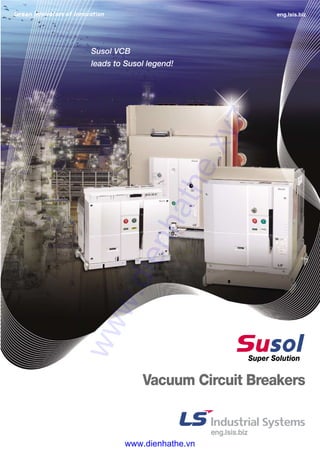
  • 1. Super Solution Susol VCB leads to Susol legend! eng.lsis.biz Vacuum Circuit Breakers www.dienhathe.xyz www.dienhathe.vn
  • 2. 2II Susol VCB lead to Susol legend! Susol VCB is full line-up new VCB which has the high interrupting capacity, large current(~50kA, ~4000A), and maximized compatibility with existing products through the dual phases and compact sized models. ● External structure 26 ● Basic features and interrupting operation 28 ● Standards and certification 31 ● Types and ordering information 32 ● Ratings 38 ● Accessories 44 ● Control circuit diagrams 76 ● Dimensions 80 ● Side-Mount Type VCB 126 ● Technical data 128 Contents www.dienhathe.xyz www.dienhathe.vn
  • 4. 4II Vacuum Circuit Breaker, VCB is installed in the medium voltage distribution lines to protect life and load equipment. In case of accidents such as over current, short circuit and ground fault current, VCB works by interrupting the circuit through the inner Vacuum Interrupter which is acted by signal from the outside separate relay. LSIS' Super Solution, Susol VCB responds. - customer needs for the breakers with high interrupting capacity and large current due to the integration and increase of the load capacity. - worldwide trend of diversification in the medium voltage distribution lines. - increase of the reliability for the temperature characteristics of circuit breakers. Premium-type products to improve convenience and reliability of medium voltage switchgear configuration. - full line-up modeling to the high interrupting capacity and large current. - main structure with high reliability application. - a variety of accessories and ability to maximize. Suitable for use as the main circuit breaker to protect key installations in the places such as device industry, power plants, high-rise buildings, large ships. www.dienhathe.xyz www.dienhathe.vn
  • 5. II5 ▶ Main circuit structure with high reliability. �Maximizing the durability and reliability of the main circuit contactors (Stego Tulip contactor). �Strong structure for the temperature rise (Natural cooling system). ▶ Convenience of switchgear configuration and a variety of accessories. �CB compartment structure: Metal isolation structures to prevent the accident spread and ensure safety. And the convenience of switchgear building is extended by its module style. �A variety of accessories: UVT, Locking Magnet, Plug Interlock, Key lock, Temperature Sensor, MOC, TOC, Earthing S/W. �Maximizing compatibility with existing products through the dualistic deployment of phases and compact models. ※ Type testing is complete for all models according to latest standard, IEC62271-100 (2008) [M2, E2 (List1 or 3), C2]. ▶ Strengthening of the high interrupting capacity and large current models and full line-up new VCB models to high/middle/low. Voltage Interrupting current Rated current 7.2kV 8/12.5/20/25/31.5/40/50kA 400/630/1250/2000/3150/4000A 12/17.5kV 20/25/31.5/40/50kA 630/1250/2000/3150/4000A 24kV 12.5/25/31.5/40kA 630/1250/2000/2500/3150A 36kV 25/31.5/40kA 1250/2000/3150A 40.5kV 25/31.5kA 1250/2000/3150A www.dienhathe.xyz www.dienhathe.vn
  • 6. 6II Susol VCB series are premium-type products featuring main structure with high reliability application and a variety of accessories and ability to maximize to be suitable for use as the main circuit breaker to protect key installations in the places such as device industry, power plants, high-rise buildings, large ships Susol VCB Family Full line‐‐up & Compact Full line-up new VCB models to the high interrupting capacity and large current (~ 50kA, ~ 4000A) featuring maximization of compatibility with existing products through the dualistic deployment of phases and compact models �Rated short-time (for withstand current ): 3sec. �Rated operating sequence: O-0.3s-CO-15s-CO �Type test level: M2, E2 (List1), C2 �Electrical and mechanical life: 30,000 operations �100% Compatibility - with existing fixed type breakers - with existing drawout type breakers �Various cradle: E, F and G type �A variety of control power - DC 24~30V, DC 48~60V, DC 110V, DC 125V, DC 220V - AC 48V, AC 100~130V, AC 220~250V �A variety of accessories - Charge switch, UVT, Secondary trip Coil, Current trip coil, Trip Latch Checking S/W, Position S/W - Key-lock, Button lock, Button cover, Padlock, UVT, Time Delay Controller, Lifting hook, CTD �TEST/SERVICE Automatic Position Indicator �Standards and certification - IEC62271-100 (2008) [M2, C2, E2 (List1)] - Tested in enclosure - KERI type tested, V-check (KESCO) certification 7.2kV (VL-06) Ur Isc Ir (kV) (kA) (A) 7.2 8 400 12.5 630 www.dienhathe.xyz www.dienhathe.vn
  • 7. II7 < < Susol VCB Series Ur Isc Ir (kV) (kA) (A) 7.2 20 630 1250 2000 25 630 1250 2000 12 20 630 1250 2000 25 630 1250 2000 17.5 20 630 1250 2000 25 630 1250 2000 �Rated short-time (to withstand current ): 3sec. 4sec* �Rated operating sequence: O-0.3s-CO-15s-CO �Type test level: M2, E2 (List3), C2 �Electrical and mechanical life: 30,000 operations �Compatibility with existing Pro-MEC breakers �Various cradle: E, F, G and H type �CB Compartment for MCSG available �A variety of control power - DC 24~30V, DC 48~60V, DC 110V, DC 125V, DC 220V - AC 48V, AC 100~130V, AC 220~250V �A variety of accessories - VCB part: Charge switch, UVT, Secondary trip coil, Latch checking switch, Position switch, Locking magnet, Plug interlock, Key lock, Button cover, Button padlock, Padlock (H type Door interlock), MOC - Cradle part: MOC (Mechanical Operated Cell switch), TOC (Truck Operated Cell switch), Temperature sensor, Earthing switch & accessaries, Door, Door interlock, Door emergency button - Others: Racking in/out handle, UVT Time delay controller, CTD (Condensor Trip Device), Temperature module �TEST/SERVICE Automatic Position Indicator �Standards and certification - IEC62271-100 (2008) [M2, C2, E2 (List3)] - KEMA, KERI type tested, V-check (KESCO) certification Note ) * Please contact us 7.2/12/17.5kV (VL-06/12/17) VCB Cradle type E type F type H type 7.2/12/17.5/24/36/40.5kV (VH-06/12/17/24/36/40) �Rated short-time (to withstand current ): 3sec. 4sec* �Rated operating sequence: O-0.3s-CO-3min-CO �Type test level: M2, E2 (List3), C2 �Electrical and mechanical life: 20,000 operations �Various cradle: K and H type �CB Compartment for MCSG available �A variety of control power - DC 48V, DC 110V, DC 125V, DC 220V - AC 48V, AC 110V, AC 220V �A variety of accessories - VCB part: UVT, Secondary trip coil, Latch checking switch, Position switch, Locking magnet, Plug interlock, Key lock, Button cover, Button padlock, Padlock (H type Door interlock), MOC - Cradle part: MOC (Mechanical Operated Cell switch), TOC (Truck Operated Cell switch), Temperature sensor, Earthing switch & accessaries, Door, Door interlock, Door emergency button - Others: Racking in/out handle, Lifting hook, UVT Time delay controller, CTD (Condensor Trip Device), Temperature module �Standards and certification - IEC62271-100 (2008) [M2, C2, E2 (List3)] - KEMA, KERI type tested, V-check (KESCO) certification Note ) * Please contact us Ur Isc Ir (kV) (kA) (A) 7.2 50 1250 12 2000 17.5 2500 3150 4000 24 25 2500 31.5 1250 2000 3150 40 1250 2000 3150 36 25 1250 2000 3150 31.5 1250 2000 3150 40 1250 2000 3150 40.5 25 1250 2000 3150 31.5 1250 2000 3150 www.dienhathe.xyz www.dienhathe.vn
  • 8. 8II Vacuum Interrupter, VI The vacuum rate within the VI is very high (approximately 5x10⁻⁵ Torr) and the spacing between fixed contact and movable contact is about 6~20mm, depending on the voltage. The contacts are in a structure that arc can easily be extinguished and the surfaces of the contacts are made of special alloy (copper- chromium) and the interior is completely sealed to prevent loss of vacuum. Therefore the wearing of the contacts can be minimized in the event of short-circuit and the arc energy by overvoltage or switching can be reduced effectively. Fixed electrode Fixed seal cup Ceramic Contacts Bellows shield Bellows Movable electrode Arc shield Movable seal cup Main circuit structure with high reliability VCB Susol� � � � � � Breaker � Insulation rod � Lower terminal � Shunt � Vacuum interrupter � Upper terminal � Tulip contactor www.dienhathe.xyz www.dienhathe.vn
  • 9. II9 < < Susol VCB Series Convenience and Variety �Maximizing the durability and reliability of the main circuit contactors (Stego Tulip contactor) �Strong structure for the temperature rise (Natural cooling system) www.dienhathe.xyz www.dienhathe.vn
  • 10. Main circuit structure with high reliability �Maximizing the durability and reliability of the main circuit contactors (Stego Tulip contactor) �Strong structure for the temperature rise (Natural cooling system) Structure of Stego Tulip Terminal �Maintaining the connection between breaker and cradle for the optimum current path through securing freedom of Tulip. �Increasing the heat dissipation area of the contactors and minimizing aging. 10II Stego Tulip Major supply records - S Electro-Mechanics, Busan plant: 12kV 40kA 4000A VCB - P Combined cogeneration power plant: 7.2kV 50kA 4000A VCB - K Petrochemical, Ulsan plant: 7.2kV 40kA 4000A VCB - P Steel plant, Gwangyang: 7.2kV 50kA 4000A VCB - P Steel plant, Pohang: 7.2kV 50kA 4000A VCB - L Chem, Cheongju plant: 7.2kV 40kA 4000A VCB - S Electronics, Tangjeong plant: 7.2kV 40kA 4000A VCB Plate understar : Securing freedom of Tulip Main circuit terminal of the breaker Tulip spring Tulip finger Plate star: Supporting Tulip for position maintaing and torsional flow prevention www.dienhathe.xyz www.dienhathe.vn
  • 11. �Drawout / natural cooling system �Improved temperature characteristics and ensured high reliability II11 < < Susol VCB Series VL type Tulip contactor VH type Tulip contactor 36kV Tulip contactor 6/12/17.5/24/36/40kV... (VH-06/12/17/24/36/40) www.dienhathe.xyz www.dienhathe.vn
  • 12. Convenience in building switchgears �CB compartment structure: H type cradle �Metal isolation structure to prevent the accident spread and ensure safety �Convenience of switchgear building CB Compartment 12II 7.2/12/17.5/24/36/40.5kV 20/25/31.5/40/50kA �Metal isolation structure to prevent the accident spread and ensure safety �Convenience of operation by Truck - Drawable in the closed position of the switchgear door - Racking-in/out positions indicated mechanically �Equipped with safety devices and accessories - Control power connected Interlock - Earthing S/W and interlock, MOC/TOC (ANSI) �Convenience in building switchgears - Module assembly with CB compartment www.dienhathe.xyz www.dienhathe.vn
  • 13. II13 < < Susol VCB Series Accessories of CB compartment (H type cradle) ■ MOC (Mechanism Operated Cell S/W) ■ TOC (Truck Operated Cell S/W) ■ Shutter Padlock ■ Temperature Sensor ■ Door Emergency ON/OFF Button ■ Earthing switch & Accessaries Key lock for Earthing S/W Locking Magnet for Earthing S/W Position S/W for Earthing S/W ■ TM (Temperature Monitoring Unit) LLVV CCoommppaarrttmmeenntt CCBB CCoommppaarrttmmeenntt PPTT CCoommppaarrttmmeenntt BBuussbbaarr && CCaabbllee CCoommppaarrttmmeenntt www.dienhathe.xyz www.dienhathe.vn
  • 14. E, F, G and H type... Variety of the Cradles Cradles E type �Economic style cradle with the basic structure �No safety shutter and bushing �For MESG �Applies VL type VCB E type 14II H typeF typeE type www.dienhathe.xyz www.dienhathe.vn
  • 15. F type G type H type II15 < < Susol VCB Series F type �Safety shutter has been added to the cradle of type E �No bushing �For MESG �Applies VL type VCB G type �Premium style cradle with safety shutter and bushings �For MESG �Applies VL type VCB H type �Metal isolation structure to prevent the accident spread and ensure safety �Convenience of operation by Truck - Drawable in the closed position of the switchgear door - Racking-in/out positions indicated mechanically - Control power connected Interlock �Convenience in building switchgears - Module assembly with CB compartment - Assembly with CT/PT integrated compartment �Applies VL/VH type VCB VL type VL type VL, VH type www.dienhathe.xyz www.dienhathe.vn
  • 16. Convenience in building switchgears - Maximizing compatibility with existing products through the dualistic deployment of phases and compact models. P150 (distance between phases: 150mm) P210 (distance between phases: 210mm) P150 (distance between phases: 150mm) P210 (distance between phases: 210mm) VCB rating VCB rating VCB rating Convenience 16II 150 150 210 210 Ur (kV) Isc (kA) Ir (A) 12 20/25 630 1250 17.5 20/25 630 1250 150 150 210 210 Ur (kV) Isc (kA) Ir (A) 12 20/25 2000 17.5 20/25 2000 210 210 275 275 Ur (kV) Isc (kA) Ir (A) 24 31.5/40 2000 25.8 31.5/40 2000 P210 (distance between phases: 210mm) P275 (distance between phases: 275mm) www.dienhathe.xyz www.dienhathe.vn
  • 17. VL type VCB (VL-06) (E/F/G type) VL type VCB (VL-06/12/17) (E/F/G type) VL/VH type VCB (H type CB compartment) Function to locking a breaker during transport of a switchgear - Fixed bracket must be dismantled first to rack in a breaker - interlocking system Fix braket easily visible from the front of the breaker II17 < < Susol VCB Series www.dienhathe.xyz www.dienhathe.vn
  • 18. A variety of accessories for VL-06 Accessories 18II � � � � � � � � � � � � � Breaker � Motor � Closing coil � Trip coil � Counter � Auxiliary contacts � UVT coil � Current trip coil � Key lock � Latch checking switch � Button padlock � Button cover � Position switch � Lead wire If accessories are attached to the breaker, the function of the breaker is upgraded. Susol VCB provides a variety of accessories depending on the purpose. www.dienhathe.xyz www.dienhathe.vn
  • 19. Cradle � Handle for Racking-in and out � UVT time delay controller � Condenser trip device A variety of accessories for VCL-06 II19 < < Susol VCB Series � � � If accessories are attached to the cradle, the function of the breaker is upgraded. Susol VCB provides a variety of accessories depending on the purpose. www.dienhathe.xyz www.dienhathe.vn
  • 20. 20II Breaker � Motor � Closing coil � Trip coil � Counter � Auxiliary contacts � UVT coil � Key lock � Latch checking switch � Button padlock � Button cover � Position switch � Handle for Racking-in/out � UVT time delay controller � Condenser trip device (CTD) � MOC � Padlock (H type Door Interlock) � Locking magnet � Plug Interlock A variety of accessories for VL-06/12/17 Accessories If accessories are attached to the breaker, the function of the breaker is upgraded. Susol VCB provides a variety of accessories depending on the purpose. www.dienhathe.xyz www.dienhathe.vn
  • 21. II21 < < Susol VCB Series Cradle (H type) � TOC (Truck operated cell s/w) � MOC (Mechanical operated cell s/w) � Temperature sensor � Door � Door interlock � Shutter padlock � Emergency ON/OFF button � Earthing switch & Accessary Key lock for Earthing switch Locking Magnet for Earthing switch Position s/w for Earthing switch � TM (Temperature monitoring unit) A variety of accessories for VL-06/12/17 If accessories are attached to the cradle, the function of the breaker is upgraded. Susol VCB provides a variety of accessories depending on the purpose. www.dienhathe.xyz www.dienhathe.vn
  • 22. A variety of accessories for VH-06/12/17/24/36/40 22II Breaker � Motor � AC/DC coil rectifier � Trip coil/Closing coil Secondary trip coil � AC/DC UVT coil rectifier � UVT coil � Latch checking switch � Auxiliary contact wire � Key lock � Button cover/Push bar � Button padlock � Position switch � Locking magnet � Plug interlock � Door Interlock for withdrawable type � Lifting hook � Charge handle � Racking in/out handle � UVT Time delay controller � CTD (Condenser trip device) Accessories If accessories are attached to the breaker, the function of the breaker is upgraded. Susol VCB provides a variety of accessories depending on the purpose. www.dienhathe.xyz www.dienhathe.vn
  • 23. A variety of accessories for VH-06/12/17/24/36/40 II23 < < Susol VCB Series Cradle (H type) � MOC (Mechanism operated cell switch) � TOC (Truck operated cell switch) � Shutter padlock � Temperature sensor � Door Emergency ON/OFF button � Earthing switch & Accessaries Key lock for Earthing switch Locking magnet for Earthing switch Position switch for Earthing switch � TM (Temperature monitoring unit) If accessories are attached to the cradle, the function of the breaker is upgraded. Susol VCB provides a variety of accessories depending on the purpose. www.dienhathe.xyz www.dienhathe.vn
  • 24. 24II E2 (List 1 or List3) E2 (List3) is first proposed in the IEC 62271-100(2008) to improve the efficiency of the interrupting test. According to it the number of interrupting test T60 is increased instead of fewer number of T10 and T30 compared to the existing List1. List3 compared with the List1 maintains the equivalent of the test but has severe test conditions because 34% higher arc energy applied to the breaker. List3 is applied to Susol VCB series. Arc Energy: List 1 (100%) < List 2 (125%) < List 3 (134%) 130 274 116 72 15 104 66 10 30 60 100(sym) 100(asym) 36 9 3 260 268 130 274 116 72 15 104 66 10 30 60 100(sym) 100(asym) 36 9 3 260 268 Thenumberofinterruptingtest Thenumberofinterruptingtest Test current (A, %×Short-circuit current) Test current (A, %×Short-circuit current) 100% E2 List1 E2 List2 E2 List3 E1 125% 134% IEC62271-100 (2002) IEC62271-100 (2008) Acr energy applied to the breaker Standards and certifications www.dienhathe.xyz www.dienhathe.vn
  • 25. II25 < < Susol VCB Series M2, C2 IEC standards to verify the relibilty of the product allows to select the quality level for the product to be tested according to its real performance and practical usage. The highest quality level of M2, C2 has been applied to Susol VCB. C1, C2: Capacitive current breaking test is to verify the probability of restriking and C2 class is secured for all Susol VCB. “O” 24 operations 2 restrikes are allowed during “CO” 24 operations “O” 24 operations Restrike is not allowed during “CO” 24 operations M1 and M2: Test to determine the mechanical durability grade �Pre-test (characteristics, isolation, and temperature) �Confirmative tests after the completion of 2000 operations (Characteristics, isolation, temperature) �Pre-test (characteristics, isolation, and temperature) �Confirmative tests after every 2000 operation �Confirmative tests after the completion of 10,000 operations (Characteristics, isolation, temperature) M1 2,0002,000 operationsoperations 2,000 operations 10,000operations C2C1 M2 2,000 operations 10,00010,000operationsoperations 10,000operations 2000 operation test Sequence Control Voltage Number of operations C-O 85% 500 C-O 100% 500 C-O 110% 500 O-CO-C 100% 250 www.dienhathe.xyz www.dienhathe.vn
  • 26. External structure of VCB 26 Breaker ... VL type Back side � Push ON Button � Push OFF Button � Charge/Discharge Indicator � ON/OFF Indicator � Manual Charging Handle � Key Lock � Operation Counter � TEST/SERVICE Position Indicator Name of each part � � � � � � � � www.dienhathe.xyz www.dienhathe.vn
  • 27. 27 Breaker ... VH type Back side � Push ON Button � Push OFF Button � Charge/Discharge Indicator � ON/OFF Indicator � Manual Charging Handle � Key Lock � Operation Counter � TEST/SERVICE Position Indicator Name of each part � � � � � � � � www.dienhathe.xyz www.dienhathe.vn
  • 28. 28 Basic functions and interrupting operation Basic functions Manual operation ①① Manual Charge a) VL type: operate the charge handle 7-8 times as a fully stroke. b) VH type: Insert the charge handle into the handle slot first. Rotate the handle clockwise 40 times more and then charge will be complete with a click sound. - When the closing spring is charged fully "CHARGED" is displayed at the charge indicator. ②② Manual closing a) Pressing the ON button the breaker is closed. b) With the closing of the breaker "ON" is displayed at Close/Trip indicator and“DISCHARGED”at the charge indicator. ③③ Manual trip a) Pressing the OFF button the breaker is opened. b)“OFF”" is displayed at Close/Trip indicator. Electric operation ①① Electric charge The breaker is remotely closing with charging of closing spring. If the breaker trips the closing spring is automatically charged by gear motors. ②② Electric closing Remote closing is operated by the closing coil. ③③ Electric trip Remote trip can be operated by the trip coil or UVT coil. Main contacts are operated by the energy of the spring mechanism and closing spring is charged by the motor in the mechanism. Breaker is closed by closing coil and tripped by trip coil. These operations are repeated in VCB as shown in the below sequence chart. Sequence of the switching mechanism Main contacts Closing coil Motor Closing spring Opening spring Trip coil Charging time of closing spring (VL type : 5 sec, VH type : 12 sec.) Control power ON Start closing Closing signal Complete closing Start opening Trip(Open) signal Complete opening Closing time Opening time www.dienhathe.xyz www.dienhathe.vn
  • 29. 29 Basic functions and interrupting operation The interruption of vacuum interrupters The interruption of VCB is carried out by the vacuum interrupters. Interrupter contacts as a key part made of copper - chromium (CuCr) material with spiral shape have low contact wear characteristics and withstand voltage is excellent. Spiral contacts make the arc generated between the surfaces of contacts rotated around the surface of contact by the induced magnetic field generated due to the spiral contact structure, which results in preventing local heating, thereby corruption and interrupting instantaneously. An example of oscillogram obtained through the interrupting test using LC resonant circuit Fixed electrode Fixed seal cup Ceramic Fixed shield Contacts Bellows shield Bellows Movable seal cup Arc shield www.dienhathe.xyz www.dienhathe.vn
  • 30. 30 Basic functions and interrupting operation The interruption of vacuum interrupters Spiral contact structure (Radial magnetic field), using the force (F = j×B) generated by the interaction of the radial magnetic field caused by the current flowing through the arc between two contacts, disperse the arc energy evenly on the surface of contact by rotating the arc that is contracted by the pinch effect so as to minimize contact damage. The images show arc behavior during the arcing time of about 8ms by shooting with high-speed camera capable of shooting 10,000 frames per sec. (0.1ms/frame) by focusing on parts of the arcing time on the above graph and simultaneously measured arc voltage also represented to show arc state by section. In case of using the flat contact any of the designs do not reflect on when contacts are opening the arc with high temperature is contracted and fixed in the center of the contacts,Which is called pinch effect. To prevent the effect two kinds of contact shapes are designed. One is Axial magnetic field which spreads the arc before its contraction, and the other is Radial magnetic field which permits the contraction of the arc but makes it rotated to disperse the energy. Because contracted arc is shaped like a cylinder it is called Contracted arc or columnar arc. Arc voltage waveforms and arc image captured during arcing time Arc driving principle in the contacts of Radial magnetic field Current Direction of rotating arc Columnar arc Radial magnetic field type contact www.dienhathe.xyz www.dienhathe.vn
  • 31. 31 Standards and certification Susol VCB has been type tested and obtained certifications according to the latest IEC standard at international testing laboratory and can be installed and applied at the environment and conditions in accordance with the standard. ●● Standard - IEC 62271-1 (2007.10) High-voltage switchgear and controlgear - Part 1: Common specifications. - IEC 62271-100 (2008.04) High-voltage switchgear and controlgear - Part 2: Alternating-current circuit breakers. ●● Test and certification �Test report (KERI) �Test report (KEMA) www.dienhathe.xyz www.dienhathe.vn
  • 32. 32 Types and ordering information 7.2kV (VL-06) Breaker Note) 1. If A2(UVT), A4 (Position S/W 2a2b) and A7(Keylock) are selected, A247 is the type name in the ordering. 2. A1(Secondary Trip Coil), A2(UVT) and A3(Current trip coil) can not be selected simultaneously. 3. A4(Position S/W 2a2a) and A5(Position S/W 2a2b) can not be selected simultaneously. 4. A8 (Button Padlock) and A9 (Button Cover) can not be selected simultaneously. 5. When A1 (Secondary Trip Coil), A2 (UVT) and A6 (Latch checking S/W) are selected the maximum available auxiliary contacts are 4a4b. 6. In case of using the existing old type cradle and replacing breaker only please order type B (Compatible with existing breaker). Compatibille busbars are required for fixed version. 7. If T9(CTC) is selected, in case of adding Secondary Trip coil, CTC is also added. Version P Fixed E E type drawout F F type drawout G G type drawout Rated voltage (kV) 06 7.2 Basic model name VL Susol VCB Interrupting current (kA) 08 8 13 12.5 Phase distance/Compatibility A Standard B Compatible with existing breaker Note6) Rated current (A) 04 400 06 630 P 04A0806VL VL-06E08A04 C1 14 7SA1M1 T1 U1 A Motor control voltage M0 Without motor M1 DC 110V M2 DC 220V M3 DC 125V M4 DC 24V~30V M5 DC 48V~60V M6 AC 48V M7 AC 100V~130V M8 AC 200V~250V Trip coil voltage T0 Without trip coil T1 DC 110V T2 DC 220V T3 DC 125V T4 DC 24V~30V T5 DC 48V~60V T6 AC 48V T7 AC 100V~130V T8 AC 200V~250V T9 Current trip coil Closing coil voltage C0 Without closing coil C1 DC 110V C2 DC 220V C3 DC 125V C4 DC 24V~30V C5 DC 48V~60V C6 AC 48V C7 AC 100V~130V C8 AC 200V~250V Other accessories Note) 1 Secondary Trip coil 4 Position S/W (2a2a) 5 Position S/W (2a2b) 6 Latch checking S/W 7 Key lock 8 Button Padlock 9 Button cover A Lead wire B User Plug (Part) O Lead Wire special color (Blue) UVT U0 Without UVT U1 DC 110V U2 DC 220V U3 DC 125V U4 DC 24V~30V U5 DC 48V~60V U6 AC 48V U7 AC 100V~130V U8 AC 200V~250V Connector and wire SA1 A type connector, 2a2b SA2 Standard A type connector, 4a4b SA3 A type connector, 6a6b SA5 A type connector, 2a2b SA6 Flame A type connector, 4a4b SA7 retardant A type connector, 6a6b Optional LH Lifting Hook CTD1 Condenser Trip Device (AC 110V) CTD2 Condenser Trip Device (AC 220V) UDC1 UVT Time Delay Controller (AC/DC 110V) UDC2 UVT Time Delay Controller (AC/DC 220V) UDC3 UVT Time Delay Controller (AC/DC 48V) CTU Coil Test Unit VC Vacuum Checker Note) A is written only once in case of more than one. www.dienhathe.xyz www.dienhathe.vn
  • 33. 33 Phase distance/Compatibility A Standard B Compatible with existing breaker Note) Cradle Version E E type drawout F F type drawout G G type drawout Rated voltage (kV) 06 7.2 Basic model name VCL Susol VCB Cradle Interrupting current (kA) 08 8 13 12.5 Rated current (A) 04 400 06 630 E 06A0806VCL Note) In case of replacing the existing old type VCB with Susol VCB please order type B for cradle and A for breaker. www.dienhathe.xyz www.dienhathe.vn
  • 34. 34 Types and ordering information Note) 1. If A2 (UVT), A4 (Position S/W 2a2b) and A7 (Keylock) are selected, A247 is the type name in the ordering. 2. A1 (Secondary Trip Coil) and A2 (UVT) can not be selected simultaneously. 3. A4 (Position S/W 2a2a) and A5 (Position S/W 2a2b) can not be selected simultaneously. 4. A8 (Button Padlock) and A9 (Button Cover) can not be selected simultaneously. 5. When A1 (Secondary Trip Coil) is selected the maximum available auxiliary contacts are 9a9b. 6. AC (Plug interlock),AD (H type Door interlock), AE (MOC) and AF (Locking magnet) are available only for H type. 7. In case of B-type connector the flame retardant wire is applicable to auxiliary contacts 4a4b, not to 10a10b. 8. A-type connector is applicable to P/E/F/G type and B-type connector to H type. 9. Lead wire special color (blue) is applicable to A-type connector. 10. In case of using position switch the available connectors are A type connector for P/E/F/G type and B type connector for H type. 11. Locking magnet can be applied only to H type VCB - breaker and cradle. 12. Locking magnet of H type breaker use the same control power supply as motor. 13. Flame retardant type blue wire is not available. 14. If T9(CTC) is selected, in case of adding Secondary Trip coil, CTC is also added. 7.2/12/17.5kV (VL-06/12/17) Breaker Version P Fixed E E type drawout (for MESG) F F type drawout (for MESG) G G type drawout (for MESG) H H type drawout (for MCSG) Note) Types of phase distance 1. Only 150mm for 7.2kV VCB 2. In case of 12 and 17.5kV VCB - 150 and 210mm for H type - 150 and 210mm for 630/1250A of P type - 210mm available for E and F type - 630A and 1250A for F (compatible with existing breaker) Rated voltage (kV) 06 7.2 12 12 17 17.5 Basic model name VL Susol VCB Interrupting current (kA) 20 20 25 25 Phase distance/Compatibility A 150mm B 210mm F Compatible with existing breaker Note) Rated current (A) 06 630 13 1250 20 2000 H 06A2006VL VL-06H20A06 Connector and wire SA2 A type connector, 4a4b SA4 Standard A type connector, 10a10b SB2 B type connector, 4a4b SB4 B type connector, 10a10b SA6 A type connector, 4a4b SA8 Flame A type connector, 10a10b SB6 retardant B type connector, 4a4b C1 SB1M1 T1 U1 Motor control voltage M0 Without motor M1 DC 110V M2 DC 220V M3 DC 125V M4 DC 24V~30V M5 DC 48V~60V M6 AC 48V M7 AC 100V~130V M8 AC 200V~250V Trip coil voltage T0 Without trip coil T1 DC 110V T2 DC 220V T3 DC 125V T4 DC 24V~30V T5 DC 48V~60V T6 AC 48V T7 AC 100V~130V T8 AC 200V~250V T9 Current trip coil Closing coil voltage C0 Without closing coil C1 DC 110V C2 DC 220V C3 DC 125V C4 DC 24V~30V C5 DC 48V~60V C6 AC 48V C7 AC 100V~130V C8 AC 200V~250V UVT U0 Without UVT U1 DC 110V U2 DC 220V U3 DC 125V U4 DC 24V~30V U5 DC 48V~60V U6 AC 48V U7 AC 100V~130V U8 AC 200V~250V Optional CTD1 Condenser Trip Device (AC 110V) CTD2 Condenser Trip Device (AC 220V) UDC1 UVT Time Delay Controller (AC/DC 110V) UDC2 UVT Time Delay Controller (AC/DC 220V) UDC3 UVT Time Delay Controller (AC/DC 48V) CTU Coil Test Unit VC Vacuum Checker 14 7A Other accessories Note) 1 Secondary Trip coil 4 Position S/W (2a2a) 5 Position S/W (2a2b) 6 Latch checking S/W 7 Key lock 8 Button Padlock 9 Button Cover B User Plug (Part) C Plug Interlock D Padlock (H type Door Interlock) E MOC (Mechanical Operating Cell S/W) F Locking Magnet O Lead Wire special color (Blue) Note) A is written only once in case of more than one. www.dienhathe.xyz www.dienhathe.vn
  • 35. 35 Cradle Note) 1.These accessories for cradle and TM can be applied only to H type. 2. AJ and AK can not be selected without door (AH). 3. TM (Temperature Monitoring) should be used with AL (Temperature Sensor). 4. H type lead wire - one of AM, AN or AO is required for cradle in case of H type breaker. Basic model name VCL Susol VCB Cradle Rated voltage (kV) 06 7.2 12 12 17 17.5 Rated short time current (kA) 20 20 25 25 Phase distance/Compatibility A 150mm B 210mm F Compatible with existing breaker Note) Rated current (A) 06 630 13 1250 20 2000 H 06A2006VCL Other accessories (H type) 1 ES (Earthing Switch) without option 2 ES with position S/W (2a2b) 4 ES with position S/W (6a6b) 5 ES with Key lock 6 ES with Locking magnet: DC 110V 7 ES with Locking magnet: DC 220V 8 ES with Locking magnet: DC 125V 9 ES with Locking magnet: DC 24V A ES with Locking magnet: DC 48V B ES with Locking magnet: AC 48V C ES with Locking magnet: AC 110V D ES with Locking magnet: AC 220V E Shutter padlock F TOC (Truck Operating Cell S/W) G MOC (Mechanical Operating Cell S/W) H Door J Door Interlock K Door Emergency Push Button L Temperature Monitoring Sensor M H type Lead wire 4a4b (Flame retardant wire) N H type Lead wire 10a10b (Flame retardant wire) O H type Lead wire 4a4b (Rated short time current) Optional TM Temperature Monitoring Version E E type drawout (for MESG) F F type drawout (for MESG) G G type drawout (for MESG) H H type drawout (for MCSG) 14 7A Note) A is written only once in case of more than one. www.dienhathe.xyz www.dienhathe.vn
  • 36. 36 Types and ordering information Note) 1. If A2 (UVT), A4 (Position S/W 2a2b) and A7 (Keylock) are selected, A247 is the type name in the ordering. 2. A1 (Secondary Trip Coil) and A2 (UVT) can not be selected simultaneously. 3. A4 (Position S/W 2a2a) and A5 (Position S/W 2a2b) can not be selected simultaneously. 4. A8 (Button Padlock) and A9 (Button Cover) can not be selected simultaneously. 5. AC (Plug interlock),AD (H type Door interlock), AE (MOC) and AF (Locking magnet) are available only for H type. 6. In case of B-type connector the flame retardant wire is applicable to auxiliary contacts 4a4b, not to 10a10b. 7. Locking magnet can be applied only to H type VCB - breaker and cradle. 8. Locking magnet of H type breaker use the same control power supply as motor. 8. A-type connector is applicable to P/E/F/G type and B-type connector to H type. 9. In case of selecting UVT A6 (Latch checking S/W) is not allowed. A6 (Latch checking S/W) is installed by default to make electrical interlock with UVT. 10. Lead wire is enclosed in the breaker in case of ordering fixed type or H type breaker without cradle, installed of cradle in case of ordering the breaker with cradle. If user plug is selected it will be enclosed in the breaker. 7.2/12/17.5/24/36/40.5kV (VH-06/12/17/24/36/40) Breaker Version P Fixed H H type drawout (for MCSG) *Phase distance is different by rating. *Phase distance only E (300mm) for 36/40.5kV VCB Note) only for 24/36kV Basic model name VH Susol VCB Interrupting current (kA) 25 Note) 25 32 31.5 40 40 50 50 Phase distance/Compatibility B 210mm D 275mm E 300mm Rated current (A) 13 1250A 20 2000A 25 2500A 32 3150A 40 4000A Rated voltage (kV) 06 7.2 12 12 17 17.5 20 24 25 25.8 36 36 40 40.5 H 13B5006VH VH-06H50B32 C1 SB2M1 T1 U1 Motor control voltage M0 Without motor M1 DC 110V M2 DC 220V M3 DC 125V M5 DC 48V M6 AC 48V M7 AC 110V M8 AC 220V UVT U0 Without UVT U1 DC 110V U2 DC 220V U3 DC 125V U5 DC 48V U6 AC 48V U7 AC 110V U8 AC 220 Note) A is written only once in case of more than one. Optional LH Lifting Hook CTD Condenser Trip Device UDC UVT Time Delay Controller DH VCB Draw-out Handle CH VCB Closing spring Charge Handle CTU Coil Test Unit VC Vacuum Checker 14 7A Other accessories Note) 1 Secondary Trip coil 4 Position S/W (2a2a) 5 Position S/W (2a2b) 6 Latch checking S/W 7 Keylock 8 Button Padlock 9 Button cover A Lead Wire B User Plug(Part) C Plug Interlock D Padlock (H type Door Interlock) E MOC (Mechanical Operating Cell S/W) F Locking Magnet P Trip Coil Monitoring Contact O Lead Wire special color (Blue) Closing coil voltage C0 Without closing coil C1 DC 110V C2 DC 220V C3 DC 125V C5 DC 48V C6 AC 48V C7 AC 110V C8 AC 220V Trip coil voltage T0 Without trip coil T1 DC110V T2 DC220V T3 DC125V T5 DC48V T6 AC 48V T7 AC 110V T8 AC 220V Connector and wire SB2 Standard B type connector, 4a4b SB4 B type connector, 10a10b SB6 Flame B type connector, 4a4b retardant www.dienhathe.xyz www.dienhathe.vn
  • 37. 37 Cradle Rated current (A) 13 1250A 20 2000A 25 2500A 32 3150A 40 4000A Note) 1.These accessories for cradle and TM can be applied only to H type. 2. AJ and AK can not be selected without door (AH). 3. TM (Temperature Monitoring) should be used with AL (Temperature Sensor). 4. H type lead wire - one of AM, AN or AO is required for cradle in case of H type breaker. Interrupting current (kA) 25 25 32 31.5 40 40 50 50 Basic model name VCL Susol VCB Cradle H 13B2506VCL Other accessories (H type) 1 ES (Earthing Switch) without option 2 ES with Position S/W (2a2b) 4 ES with Position S/W (6a6b) 5 ES with Key lock 6 ES with Locking magnet: DC 110V 7 ES with Locking magnet: DC 220V 8 ES with Locking magnet: DC 125V A ES with Locking magnet: DC 48V B ES with Locking magnet: AC 48V C ES with Locking magnet: AC 110V D ES with Locking magnet: AC 220V E Shutter padlock F TOC (Truck Operating Cell S/W) G MOC (Mechanical Operating Cell S/W) H Door J Door Interlock K Door Emergency Push Button L Temperature Sensor M H type Lead wire 4a4b (Flame retardant wire) N H type Lead wire 10a10b (Flame retardant wire) O H type Lead wire 4a4b (Rated short time current) Optional TM Temperature Monitoring Version K K type drawout H H type drawout (for MCSG) Phase distance/Compatibility B 210mm D 275mm E 300mm Rotated bushing F type (210mm) 14 7A Rated voltage (kV) 06 7.2 12 12 17 17.5 20 24 25 25.8 36 36 40 40.5 Note) A is written only once in case of more than one. www.dienhathe.xyz www.dienhathe.vn
  • 38. 38 Ratings - 7.2kV 8/12.5kA 400/600A 7.2kV (VL-06) * Lifetime with maintenance. Item VL-06�� 08��04 VL-06��13�� 06 Rated voltage Ur (kV) 7.2 Rated normal current Ir (A) 400 630 Rated frequency fr (Hz) 50/60 Rated short-circuit current Isc (kA) 8 12.5 Rated short-time withstand current Ik/tk (kA/s) 8/3 12.5/3 Rated short-circuit breaking capacity (MVA) 100 160 Rated short-circuit making current Ip (kA) 2.5* Isc (50Hz)/2.6* Isc (60Hz) Rated breaking time (cycle) 3 Rated withstand Power frequency (1 min) Ud (kV) 20 voltage Impulse (1.2×50㎲) Up (kV) 60 Rated operating sequence O-0.3s-CO-15s-CO Control voltage Closing coil (V) AC/DC 100~130V, AC/DC 200~250V, DC 125V, DC 24~30V, DC 48~60V, AC 48V Trip coil (V) AC/DC 100~130V, AC/DC 200~250V, DC 125V, DC 24~30V, DC 48~60V, AC 48V Auxiliary contacts 2a2b, 4a4b, 6a6b Rated opening time (sec) ≤ 0.04 No-load closing time (sec) ≤ 0.06 Type test class Mechanical M2 Electrical E2 (List1) Capacitive current switching C2 Lifetime * Mechanical (Operations) 30,000 Electrical (Operations) See graph, Page 117~118 Installation version Fixed P type Drawout E, F, G type (for MESG) Phase distance (mm) 130 Weight Breaker (E, F, G type) (kg) 37 37 Cradle (E, F, G type) (kg) 18, 25, 32 19, 26, 33 Dimensions Breaker (E, F, G type) Page 80~81 Cradle (E, F, G type) Page 81~82 Standards IEC 62271-100 (2008), KS C 4611, JEC 2300/JIS C 4603, V-check (KESCO) www.dienhathe.xyz www.dienhathe.vn
  • 39. 39 Ratings - 7.2/12/17.5kV 20/25kA 630/1250/2000A 7.2/12/17.5kV (VL-06/12/17) * Lifetime with maintenance. ** H type is a box type cradle with CB compartment style structure. *** ( ) displays option of phase distance. Item VL-06��20/25��06/13/20 VL-12�� 20/25��06/13/20 VL-17��20/25��06/13/20 Rated voltage Ur (kV) 7.2 12 17.5 Rated normal current Ir (A) 630 1250 2000 630 1250 2000 630 1250 2000 Rated frequency fr (Hz) 50/60 Rated short-circuit current Isc (kA) 20, 25 Rated short-time withstand current Ik/tk (kA/s) 20/3, 25/3 Rated short-circuit breaking capacity (MVA) 250/310 410/520 600/750 Rated short-circuit making current Ip (kA) 2.5* Isc (50Hz)/2.6* Isc (60Hz) Rated breaking time (cycle) 3 Rated withstand Power frequency (1 min) Ud (kV) 20 28 (42) 38 voltage Impulse (1.2×50㎲) Up (kV) 60 75 95 Rated operating sequence O-0.3s-CO-15s-CO Control voltage Closing coil (V) DC 24~30V, DC 48~60V, DC 110V, DC 125V, DC 220V, AC 48V, AC 100~130V, AC 220~250V Trip coil (V) DC 24~30V, DC 48~60V, DC 110V, DC 125V, DC 220V, AC 48V, AC 100~130V, AC 220~250V Auxiliary contacts 4a4b, 10a10b Rated opening time (sec) ≤ 0.04 No-load closing time (sec) ≤ 0.06 Type test class Mechanical M2 Electrical E2 (List3) Capacitive current switching C2 Lifetime * Mechanical (Operations) 30,000 Electrical (Operations) See graph, Page 117~118 Installation version ** Fixed P type P type Drawout E, F, G type (for MESG), H type (for MCSG) E, F type (for MESG), H type (for MCSG) Phase distance *** (mm) 150 150 (210) 150 (210) Weight Breaker (E, F, G type) (kg) 100 100 130 115 (120) 115 (120) 130 (140) 115 (120) 115 (120) 130 (140) Cradle (E, F, G type) (kg) 170 170 180 170 (200) 170 (200) 180 (200) 170 (200) 170 (200) 180 (200) Dimensions Breaker (E, F, G type) Page 83~85 Page 85~87 Page 87~91 Page 91~93 Page 87~91 Page 91~93 Cradle (E, F, G type) Page 100, 102 Page 101~102 Page 103~105 Page 106 Page 103~105 Page 106 Cradle (H type) Page 94 Page 95 Page 96~97 Page 98~99 Page 96~97 Page 98~99 Standards IEC 62271-100 (2008), KERI/KEMA, V-check (KESCO) www.dienhathe.xyz www.dienhathe.vn
  • 40. 40 Ratings - 7.2/12/17.5kV 25/31.5/40/50kA 1250/2000/2500/3150/4000A 7.2/12/17.5kV (VH-06/12/17) * Lifetime with maintenance. ** K type is a 4000A exclusive cradle. Item VH-06��50��12/20/25/32/40 VH-12��50��12/20/25/32/40 VH-17��50��12/20/25/32 Rated voltage Ur (kV) 7.2 12 17.5 Rated normal current Ir (A) 1250 2000 2500 3150 4000 1250 2000 2500 3150 4000 1250 2000 2500 3150 Rated frequency fr (Hz) 60 Rated short-circuit current Isc (kA) 50 Rated short-time withstand current Ik/tk (kA/s) 50/3 Rated short-circuit breaking capacity (MVA) 623 1039 1515 Rated short-circuit making current Ip (kA) 2.6* Isc (60Hz) Rated breaking time (cycle) 3 Rated withstand Power frequency (1 min) Ud (kV) 20 28 38 voltage Impulse (1.2×50㎲) Up (kV) 60 75 95 Rated operating sequence O-0.3s-CO-3min-CO Control voltage Closing coil (V) DC 48V, DC 110V, DC 125V, DC 220V, AC 48V, AC 110V, AC 220V Trip coil (V) DC 48V, DC 110V, DC 125V, DC 220V, AC 48V, AC 110V, AC 220V Auxiliary contacts 4a4b, 10a10b Rated opening time (sec) ≤ 0.04 No-load closing time (sec) ≤ 0.06 Type test class Mechanical M2 Electrical E2 (List3) Capacitive current switching C2 Lifetime * Mechanical (Operations) 20,000 Electrical (Operations) See graph, Page 117~118 Installation version ** Fixed P type - P type - P type Drawout H type (for MCSG) K type H type (for MCSG) K type H type (for MCSG) Phase distance (mm) 210 275 275 210 275 275 210 275 Weight Breaker (H type) (kg) 230 287 290 385 230 287 290 385 230 287 290 Cradle (H, K type) (kg) 175 320 320 315 175 320 320 315 175 320 320 Dimensions Breaker (H type) Page 107 Page 108 Page 109 Page 107 Page 109 Page 109 Page 107 Page 108 Cradle (H, K type) Page 118 Page 119 Page 109 Page 118 Page 119 Page 109 Page 118 Page 119 Standards IEC 62271-100 (2008), KERI/KEMA, V-check (KESCO) www.dienhathe.xyz www.dienhathe.vn
  • 41. 41 * Lifetime with maintenance. ** H type is a box type cradle with CB compartment style structure. *** ( ) displays option of phase distance. Note) 1. Contact us. Item VH-20��25��25 VH-20��32��12/20/32 VH-20�� 40�� 12/20/32 Rated voltage Ur (kV) 24/25.8 Rated normal current Ir (A) 2500 1250 2000 3150 1250 2000 3150 Rated frequency fr (Hz) 60 Rated short-circuit current Isc (kA) 25 31.5 40 Rated short-time withstand current Ik/tk (kA/s) 25/3 31.5/3 40/3 Rated short-circuit breaking capacity (MVA) 1039/1117 1309/1407 1662/1787 Rated short-circuit making current Ip (kA) 2.6* Isc (60Hz) Rated breaking time (cycle) 3 Rated withstand Power frequency (1 min) Ud (kV) 60 (65) Note1) voltage Impulse (1.2×50㎲) Up (kV) 125 Rated operating sequence O-0.3s-CO-3min-CO Control voltage Closing coil (V) DC 48V, DC 110V, DC 125V, DC 220V, AC 48V, AC 110V, AC 220V Trip coil (V) DC 48V, DC 110V, DC 125V, DC 220V, AC 48V, AC 110V, AC 220V Auxiliary contacts 4a4b, 10a10b Rated opening time (sec) ≤ 0.04 No-load closing time (sec) ≤ 0.06 Type test class Mechanical M2 Electrical E2 (List3) Capacitive current switching C2 Lifetime * Mechanical (Operations) 20,000 Electrical (Operations) See graph, Page 117~118 Installation version ** Fixed P type Drawout H type (for MCSG) Phase distance *** (mm) 275 210 210 (275) 275 210 210 (275) 275 Weight Breaker (H type) (kg) 295 256 256 (273) 318 256 256 (273) 318 Cradle (H type) (kg) 316 257 257 (284) 316 257 257 (284) 316 Dimensions Breaker (H type) Page 110 Page 111~112 Page 113 Page 111~112 Page 113 Cradle (H type) Page 123 Page 120~122 Page 123 Page 120~122 Page 123 Standards IEC 62271-100 (2008), KERI/KEMA, V-check (KESCO) 24kV (VH-20) www.dienhathe.xyz www.dienhathe.vn
  • 42. 42 Ratings - 7.2/12/17.5kV 25/31.5/40/50kA 1250/2000/2500/3150/4000A * Lifetime with maintenance. ** H type is a box type cradle with CB compartment style structure. Note) 1. Contact us. Item VH-36��25��12/20/32 VH-36��32��12/20/32 VH-36��40��12/20/32 Rated voltage Ur (kV) 36 Rated normal current Ir (A) 1250 2000 3150 1250 2000 3150 1250 2000 3150 Rated frequency fr (Hz) 50/60 Rated short-circuit current Isc (kA) 25 31.5 40 Rated short-time withstand current Ik/tk (kA/s) 25/3 31.5/3 40/3 Rated short-circuit breaking capacity (MVA) 1559 1964 2494 Rated short-circuit making current Ip (kA) 2.5* Isc (50Hz)/2.6* Isc (60Hz) Rated breaking time (cycle) 3 Rated withstand Power frequency (1 min) Ud (kV) 70 (95) Note1) voltage Impulse (1.2×50㎲) Up (kV) 170 Rated operating sequence O-0.3s-CO-3min-CO Control voltage Closing coil (V) DC 48V, DC 110V, DC 125V, DC 220V, AC 48V, AC 110V, AC 220V Trip coil (V) DC 48V, DC 110V, DC 125V, DC 220V, AC 48V, AC 110V, AC 220V Auxiliary contacts 4a4b, 10a10b Rated opening time (sec) ≤ 0.04 No-load closing time (sec) ≤ 0.06 Type test class Mechanical M2 Electrical E2 (List3) Capacitive current switching C2 Lifetime * Mechanical (Operations) 20,000 Electrical (Operations) See graph, Page 117~118 Installation version ** Fixed P type Drawout H type (for MCSG) Phase distance (mm) 300 Weight Breaker (H type) (kg) 400 490 400 490 400 490 Cradle (H type) (kg) 700 750 700 750 700 750 Dimensions Breaker (H type) Page 114 Page 115 Page 114 Page 115 Page 114 Page 115 Cradle (H type) Page 124 Page 125 Page 124 Page 125 Page 124 Page 125 Standards IEC 62271-100 (2008), KERI/KEMA, V-check (KESCO) 36kV (VH-36) www.dienhathe.xyz www.dienhathe.vn
  • 43. 43 * Lifetime with maintenance. ** H type is a box type cradle with CB compartment style structure. Item VH-40��25��12/20/32 VH-40��32��12/20/32 Rated voltage Ur (kV) 40.5 Rated normal current Ir (A) 1250 2000 3150 1250 2000 3150 Rated frequency fr (Hz) 50 Rated short-circuit current Isc (kA) 25 31.5 Rated short-time withstand current Ik/tk (kA/s) 25/4 31.5/4 Rated short-circuit breaking capacity (MVA) 1754 2210 Rated short-circuit making current Ip (kA) 2.5* Isc (50Hz) Rated breaking time (cycle) 3 Rated withstand Power frequency (1 min) Ud (kV) 95 voltage Impulse (1.2×50㎲) Up (kV) 180 Rated operating sequence O-0.3s-CO-3min-CO Control voltage Closing coil (V) DC 48V, DC 110V, DC 125V, DC 220V, AC 48V, AC 110V, AC 220V Trip coil (V) DC 48V, DC 110V, DC 125V, DC 220V, AC 48V, AC 110V, AC 220V Auxiliary contacts 4a4b, 10a10b Rated opening time (sec) ≤ 0.04 No-load closing time (sec) ≤ 0.06 Type test class Mechanical M2 Electrical 20 Operations at 100% Isc Capacitive current switching C2 Lifetime * Mechanical (Operations) 20,000 Electrical (Operations) See graph, Page 117~118 Installation version ** Fixed P type Phase distance (mm) 300 Weight Breaker (H type) (kg) 400 490 400 490 Dimensions Breaker (H type) Page 116 Page 117 Page 116 Page 117 Standards GB1984 40.5kV (VH-40) www.dienhathe.xyz www.dienhathe.vn
  • 44. Accessory 44 * ●: Basic Installation Mounting Supplied as Position Type Accessory VL: 7.2kV VL: 20/25kA VH Remarks page 8/12.5kA Breaker M Motor ● ● ● Attached at the factory 46 (Internal) CC Closing Coil ● ● ● Attached at the factory 47 TC Trip Coil ● ● ● Attached at the factory 48 A1 Secondary Trip Coil Option Option Option Attached at the factory 49 T9 Current Trip Coil Option - - Attached at the factory 50 Auxiliary Contact (2a2b) ● - - Attached at the factory 51 SA Auxiliary Contact (4a4b) Option ● ● 51 (SB) Auxiliary Contact (6a6b) Option - - 51 Auxiliary Contact (10a10b) - Option Option 51 U Under Voltage Trip Coil Option Option Option Attached at the factory 52 A4 Position Switch (2a2a) Option Option Option Attached at the factory 53 A5 Position Switch (2a2b) Option Option Option Attached at the factory 53 A6 Latch Checking Switch Option Option Option Attached at the factory 54 C Counter ● ● ● Attached at the factory 54 A7 Keylock Option Option Option Attached at the factory 55 A8 Button Padlock Option Option Option Attached at the factory 56 A9 Button cover Option Option Option Attached at the factory 57 AA Lead Wire: A/B type connector Option Option Option Attached at the factory 58 AB Plug/Terminal for Lead Wire Option Option Option Attached at the factory 59 AC Plug Interlock - Option Option Attached at the factory 59 AD Padlock (Type H Door Interlock) - Option Option Attached at the factory 59 AE MOC (Mechanical Operated Cell Switch - Option Option Attached at the factory 60 AF Locking Magnet - Option Option Attached at the factory 61 AO Lead Wire: A type connector Option Option - Attached at the factory 58 (Special Color: Blue) AP Trip Coil Monitoring Contact ● ● Option Attached at the factory 62 Breaker CTD1 Condenser Trip Device (AC 110V) Option Option Option - 64 (External) CTD2 Condenser Trip Device (AC 220V) Option Option Option - 64 UDC 1 UVT Time Delay Controller (AD 110V) Option Option Option - 65 UDC 2 UVT Time Delay Controller (AD 220V) Option Option Option - 65 UDC 3 UVT Time Delay Controller (AD 48V) Option Option Option - 65 CTU Coil Test Unit Option Option Option - 63 VC Vacuum Checker Option Option Option - 66 TM Temperature Monitoring - Option Option - 67 www.dienhathe.xyz www.dienhathe.vn
  • 45. 45 Mounting Supplied as Position Type Accessory VL: 7.2kV VL : 20/25kA VH Remarks page 8/12.5kA Cradle A1 ES (Earthing Switch) without Option - Option Option Attached at the factory 68 A2 ES (Earthing Switch) - Option Option Attached at the factory 68 with Position Switch (2a2b) A4 ES (Earthing Switch) - Option Option Attached at the factory 68 with Position Switch (6a6b) A5 ES (Earthing Switch) with Keylock - Option Option Attached at the factory 69 A6 ES (Earthing Switch) - Option Option Attached at the factory 69 with Locking magnet: DC 110V A7 ES (Earthing Switch) - Option Option Attached at the factory 69 with Locking magnet: DC 220V A8 ES (Earthing Switch) - Option Option Attached at the factory 69 with Locking magnet: DC 125V A9 ES (Earthing Switch) - Option Option Attached at the factory 69 with Locking magnet: DC 24V AA ES (Earthing Switch) - Option Option Attached at the factory 69 with Locking magnet: DC 48V AB ES (Earthing Switch) - Option Option Attached at the factory 69 with Locking magnet: AC 48V AC ES (Earthing Switch) - Option Option Attached at the factory 69 with Locking magnet: AC 110V AD ES (Earthing Switch) - Option Option Attached at the factory 69 with Locking magnet: AC 220V AE Shutter padlock - Option Option Attached at the factory 70 AF TOC (Truck Operated Cell Switch) - Option Option Attached at the factory 70 AG MOC (Mechanical Operated Cell Switch) - Option Option Attached at the factory 71 AH Door - Option Option Attached at the factory 71 AJ Door Interlock - Option Option Attached at the factory 72 AK Door Emergency Push Button - Option Option Attached at the factory 72 AL Temperature Sensor - Option Option Attached at the factory 73 AM Type H Lead Wire 4a4b (Normal cable) - Option Option Attached at the factory 74 AN Type H Lead Wire 10a10b (Normal cable) - Option Option Attached at the factory 74 AO Type H Lead Wire 4a4b - Option Option Attached at the factory 74 (Flame retardant cable) Door padlock - Option Option Attached at the factory 74 www.dienhathe.xyz www.dienhathe.vn
  • 46. Accessory 46 Motor: M VL type �Charge the closing spring of a circuit breaker by the external power source. When the charging is complete, control power of the motor will be "OFF" by the built-in Limit S/W. Without the external power source, charge manually. Operating voltage range (IEC 60947) 85%~110%Vn Motor VL type Input voltage (Vn) DC 24~ DC 48~ DC 110V DC 125V DC 220V AC 48V AC 100~ AC 200~ 30V 60V 130 250V Load current (A) 5 3 1 1 0.5 3 1 0.5 Starting current (A) 5 times of load current Charge time Less than 5 sec. VH type VH Type Input voltage (Vn) DC 48V DC 110V DC 125V DC 220V AC 48V AC 110V AC 220V Load current (A) 6 3 3 2.6 6 3 2.6 Starting current (A) 30 20 20 17 30 20 17 Charge time Less than 12 sec. Motor Main shaft Charge completion contact Gear Motor Note) Rated operation and control voltage range, see page 50. Note) Rated operation and control voltage range, see page 50. Installed inside of a breaker as standard www.dienhathe.xyz www.dienhathe.vn
  • 47. 47 Closing Coil: C VL type �It is a control device which closes a circuit breaker, when applying voltage continuously or instantaneously over 200ms to the coil control terminals. VL type Input voltage (Vn) DC 24~ DC 48~ DC 110V DC 125V DC 220V AC 48V AC 100~ AC 200~ 30V 60V 130 250V Power consumption (inrush, W) 200 Power consumption (steady, W) 5 VH type �It is a control device which closes a circuit breaker, when applying voltage continuously about 45ms to the coil control terminals. Electrical pumping preventing circuit is built in. VH Type Input voltage (Vn) DC 48V DC 110V DC 125V DC 220V AC 48V AC 110V AC 220V Rated current (A) 8 3 3 2.5 8 3 2.5 Closing coil Closing coil Note) Rated operation and control voltage range, see page 50. Note) Rated operation and control voltage range, see page 50. Installed inside of a breaker as standard www.dienhathe.xyz www.dienhathe.vn
  • 48. Accessory 48 Trip Coil: T VL type �It is a control device which trips a circuit breaker from remote place, when applying voltage continuously or instantaneously over 35ms to coil control terminals. �When UVT coil is installed, its location is changed. VL type Input voltage (Vn) DC 24~ DC 48~ DC 110V DC 125V DC 220V AC 48V AC 100~ AC 200~ 30V 60V 130 250V Power consumption (inrush, W) 200 Power consumption (steady, W) 5 VH type �It is a control device which trips a circuit breaker, when applying voltage continuously or instantaneausly over 35ms to the coil control terminals. VH Type Input voltage (Vn) DC 48V DC 110V DC 125V DC 220V AC 48V AC 110V AC 220V Rated current (A) 8 3 3 2.5 8 3 2.5 Trip coil Trip coil Note) Rated operation and control voltage range, see page 50. Note) Rated operation and control voltage range, see page 50. Installed inside of a breaker as standard www.dienhathe.xyz www.dienhathe.vn
  • 49. 49 Secondary Trip Coil: A1 VL type �It is a control device which trips a circuit breaker doubly from the outside. If the trip coil (T ) fails, it can trip a circuit breaker safely. �Trip coil: Install it at existing location. �Secondary trip coil: Install it on the right side of the trip coil. �It is not available with UVT coil when installing secondary trip coil. VL type Input voltage (Vn) DC 24~ DC 48~ DC 110V DC 125V DC 220V AC 48V AC 100~ AC 200~ 30V 60V 130 250V Power consumption (inrush, W) 200 Power consumption (steady, W) 5 VH type �It is a control device which trips a circuit breaker doubly from the outside. If the trip coil (T) fails, it can trip a circuit breaker safely. �It is not available with UVT coil when installing secondary trip coil. VH Type Input voltage (Vn) DC 48V DC 110V DC 125V DC 220V AC 48V AC 110V AC 220V Rated current (A) 8 3 3 2.5 8 3 2.5 Secondary Trip coil Secondary Trip coil Installed inside of a breaker as an option www.dienhathe.xyz www.dienhathe.vn
  • 50. Accessory 50 Rated operation and control voltage range Item Susol VCB Remarks VL: 7.2kV 8/12.5kA VL: 20/25kA VH Motor AC 85~110% 85~110% 85~110% DC 75~110% 85~110% 85~110% Closing AC 85~110% 85~110% 85~110% DC 75~125% 85~110% 85~110% Trip AC 60~125% 85~110% 85~110% DC 60~125% 70~110% 70~110% Applied standards IEC62271-100 (2008) IEC62271-100 (2008) IEC62271-100 (2008) KSC4611 Current Trip Coil: T9 VL type �This trip coil uses the output of the CT as its control power source and is used with over current relay in combination. Two current trip coils are supplied. �Applies only to 7.2kV 8/12.5kA VCB. �Coil burden is 90VA. �Coil impedance (Z) is 10Ω or less. (Operating current is AC 3A) �CT must be installed at load side. If it is installed at bus side there is the danger of malfunction or damage to CT. �Don’t disconnect the control power connector on main power is live condition at service position. Otherwise there is the danger of malfunction or damage to CT. Current Trip Coil Installed inside of a breaker as an option www.dienhathe.xyz www.dienhathe.vn
  • 51. 51 Auxiliary Contact: SA VL type �It is a contact used to monitor ON/OFF status of a breaker from remote place. �The auxiliary contacts supplied as standard configuration is 4a4b. 10a10b is also available on request. �For 7.2kV 8/12.5kA VCB standard configuration is 2a2b. 4a4b and 6a6b are optional. Auxiliary contact VH type VL/VH Type Item Resistive load (A) Inductive load (A) Remarks AC 250V 10 5 Contact 125V 10 5 configuration 250V 10 5 For all models DC 125V 10 5 30V 10 5 Auxiliary contact Item VL: 7.2kV VL: 20/25kA, 8/12.5kA VH Standard 2a2b 4a4b Optional 4a4b, 6a6b 10a10b Installed inside of a breaker as an option www.dienhathe.xyz www.dienhathe.vn
  • 52. Accessory 52 Under Voltage Trip Coil: U VL type VH type �It is installed inside of a breaker to trip when the main power or control power voltage drops below certain value. Instantaneous type is only available with UVT coil and Time delay type is available by connecting UVT coil and UVT time delay controller. �The closing of a circuit breaker is impossible mechanically or electrically if control power is not supplied to UVT. To close the circuit breaker, 65~85% of rated voltage should be applied. �UVT and secondary trip coil will not be selected together. 1. UVT rated voltage and characteristic - Operating voltage range: Pick up 0.65~0.85Vn, Drop out 0.4~0.6Vn - Operating voltage ranges based on the minimum value of each rated voltage (Vn) VL type VH type VL type Input voltage (Vn) DC 24~ DC 48~ DC 110V DC 125V DC 220V AC 48V AC 100~ AC 200~ 30V 60V 130 250V Power consumption (inrush, W) 200 Power consumption (steady, W) 5 VH Type Input voltage (Vn) DC 48V DC 110V DC 125V DC 220V AC 48V AC 110V AC 220V Power consumption (inrush, W) 200 Power consumption (steady, W) 5 Under Voltage Trip Coil Under Voltage Trip Coil Installed inside of a breaker as an option www.dienhathe.xyz www.dienhathe.vn
  • 53. 53 Position Switch: A4, A5 VL type - E/F/G Cradle VL: 7.2kV 8/12.5kA VL: 20/25kA Small VCB (VL) VL/VH type - H Cradle VL: 20/25kA VH �This switch is used to indicate the breaker position (SERVICE, TEST), and contact configuration is 2a2a or 2a2b. Medium VCB (VL) Large model (VH) 1 3 5 7 2 4 6 8 1 3 5 7 2 4 6 8 2a(TEST) 2a(SERVICE) 1a1b(TEST) 1a1b(SERVICE) Contact configuration Position switch Position switch Position switch Position switch Installed inside of a breaker as an option www.dienhathe.xyz www.dienhathe.vn
  • 54. Accessory 54 Latch checking switch: A6 VL type �This switch works in conjunction with the mechanism of the breaker. It checks if the breaker is ready to be closed. �When the mechanism is OFF and the closing spring is at charged status the switch becomes "ON", which means the mechanism is ready to be closed. �If the latch is not in a proper position the switch prevents the breaker from closing. In case of VL type, if it is connected in series with the closing coil, it is possible to prevent the breaker from closing electrically even though the closing signal happening when trip latch is in wrong position. �In case of VH type it is connected internally in series with the closing coil. Counter: C VL/VH type �It displays the total number of ON/OFF operations of a breaker. VH type Latch checking switch Latch checking switch Installed inside of a breaker as standard Installed inside of a breaker as an option www.dienhathe.xyz www.dienhathe.vn
  • 55. 55 Keylock: A7 VL type �The key is to unlock the locking device first to close the breaker electrically and mechanically. *How to operate - It is not possible to pull out the key in the unlocked position, possible only in locked status. - Pushing "OFF" switch of a breaker turn the key counter-clockwise to the locked position and pull it out. - It is not possible to close the breaker electrically and mechanically in the locked position. - Insert the key and turn clockwise and then the breaker can be closed electrically and mechanically. *How to operate - It is not possible to pull out the key in the unlocked position, possible only in locked status. - Trip the breaker first and then turn the key counter-clockwise to the locked position and pull it out. - It is not possible to close the breaker electrically and mechanically in the locked position. VH type Keylock Keylock Installed inside of a breaker as an option www.dienhathe.xyz www.dienhathe.vn
  • 56. Accessory 56 Button Padlock: A8 VL type �It is to prevent manual operation of ON/OFF button due to user’s wrong handling. �It is not possible to handle ON/OFF operation under the “Button lock” status. Button Padlock Button Padlock VH type Installed outside of a breaker as an option www.dienhathe.xyz www.dienhathe.vn
  • 57. 57 Button Cover: A9 VL type �It is a protection cover to prevent an accident due to unintended operation of ON/OFF button. �Use the push-bar to operate the ON/OFF button. VH type Button Cover Button Cover Push Bar Push Bar Installed outside of a breaker as an option www.dienhathe.xyz www.dienhathe.vn
  • 58. Accessory 58 Lead wire : AA VL/VH type �It is to connect with the control circuit of a breaker from outside. (supply wire length: 2m) �A type connector is supplied for P/E/F/G type of VL VCB. �B type connector is supplied for P type of VH VCB. �In case of H type breaker of VL and VH models the Lead wire is installed in the cradle when supplied. Lead wire Plug/Terminal for lead wire VL/VH type �It is connector to connect with the connector installed in the breaker. (supply connectors and terminal only for lead wire) �Type of connector is depends on the type of connector installed in the breaker- A or B. A type connector B type connector A type connector B type connector Supply ways of Lead wires by VCB model P E F G H Lead wire of A type connector Lead wire of B type connector Enclosed in the breaker Installed in the cradle Lead wire of B type connector - Lead wire of B type connector Installed in the breaker - Installed in the cradle Lead wire type VL Supply way Lead wire type VH Supply way VCB model Cradle type Supplied separately from a breaker as an option Supplied separately from a breaker as an option www.dienhathe.xyz www.dienhathe.vn
  • 59. 59 Plug interlock: AC VL/VH type (7.2kV 20/25kA 630A~) �It checks if the control power connector on the cradle (H type) is connected with the connecting terminal of the breaker before the proceeding of draw-in or out. �It is not allowed to seperate the control power connector from the breaker in the position of draw-in /out or SERVICE, but TEST position. Padlock/Door racking interlock: AD VL/VH type (7.2kV 20/25kA 630A~) �With this door options for H type cradle draw- in/out is allowed only when the door is closed. �If draw-in /out is necessary when the door is open, use the operation lever put in the slot of the breaker handle. Insert it into the hole in the bottom of door interlock. �Padlock is also optional, which can lock to prevents the draw-in/out of the breaker in the position of TEST and SERVICE. Plug interlock Door interlock Installed outside of a breaker as an option Installed inside of a breaker as an option www.dienhathe.xyz www.dienhathe.vn
  • 60. Accessory 60 MOC drive device: AE VL type (7.2kV 20/25kA 630A~) �It must be installed in the breaker to drive the MOC installed in H type cradle. �MOC, Mechanically operated cell switch is the device to indicates the Closed/Trip status of VCB in 'SERVICE' position only. �This MOC drive device in the breaker should be installed when MOC in the cradle is used. MOC VH type MOC Installed inside of a breaker as an option www.dienhathe.xyz www.dienhathe.vn
  • 61. 61 Locking magnet: AF VL type �It allows the drawing-in of the breaker in the TEST position under the condition that the control power connector on the cradle (H type) is connected with the connecting terminal of the breaker and the power is supplied. �During the drawing-in or in the SERVICE position draw-in/out is allowed without supplying power. * Control power rating is the same as that of a motor. Locking magnet VH type Locking magnet Installed inside of a breaker as an option www.dienhathe.xyz www.dienhathe.vn
  • 62. Accessory 62 Trip coil monitoring contact: AP VL type �Device for monitoring the functions of the trip coils. �Supplied as standard for VL model and optional for VH model. �To monitor the trip coils connect its terminals with the trip coil monitoring relay as shown on the circuit diagram. - If the trip coil is normal: closed-circuit consisting - If the trip coil is damaged: open circuit 1) Terminals A5 and A6 monitor the trip coils in closed position of the breaker. 2) Terminal A6 and aux. contact terminal 34 monitor the trip coils in trip position of the breaker. �Coil Test Unit is opional, which enable monitoring the coils by connecting in parallel with the trip coil operation switch. 10a 10b 4a 4b VH type 10a 10b 4a 4b Installed inside of a breaker as an option www.dienhathe.xyz www.dienhathe.vn
  • 63. 63 Coil Test Unit: CTU �When no current flows through the coil it gives the test current which does not cause the coil to operate to check whether the coil is disconnected or not. - If the test current flows normally: coil normal - If the test current does not flow through: coil disconnected ※※ As it is connected in parallel with the control part of the coil the normal operation of the coil is not affected. ※※ Monitoring of the running coils is not possible. ※※ One test unit can monitor up to two coils. 1. Input voltage: AC/DC 75V~264V 2. Contact output 1) 2×a contacts for Fail indication and 2×a contacts for Alarm 2) 250Vac/10A Resistive, 30Vdc/10A Resistive 3. Disconnection test cycle is 12 seconds (Test LED blinks) 4. The default operation If Fail happens (coil disconnected), Fail LED turns on and the Fail contacts become short state. If Fail happens three times in series, Alarm LED turns on and the Alarm contacts become short state. In order to clear the Alarm status push up DIP switch on the front and then push down it (Off → On → Off) Shunt 1 24~250V (AC/DC) Shunt 2 AC/DC 75~264V Fail 1 Alarm 1 Fail 2 Alarm 2 Coil Test Unit 24~250V (AC/DC) Input voltage Fail (LED) Fail (RELAY) Alarm (LED) Alarm (RELAY) Coil Test Unit Coil drive power(+) Coil drive power(-) Coil drive power CTU Input voltage (+) CTU Input voltage (+) Coil test current Coil 1 5 7 2 Installed outside of a breaker as an option www.dienhathe.xyz www.dienhathe.vn
  • 64. Accessory 64 �It gets a circuit breaker tripped electrically within regular time when control power supply is broken down and is used with Shunt coil, SHT. In case there is no DC power, It can be used as the rectifier which supplies DC power to a circuit breaker by rectifying AC power. �Tripping within 30 seconds on the power failure is possible. However after that automatic trip circuit must be configured separately in the switchgear. Condenser trip device: CTD Terminal arrangement Circuit diagram D1 TNR SW1 LAMP R3 R1 1 3 5 6 R2 AC Input DC Output for discharge1000/ 560uF External dimension (Mounting hole) Ratings Ratings Specification Model CB - T1 CB - T2 Rated input voltage (V) AC 100/110 AC 200/220 Frequency (Hz) 50/60 50/60 Rated charge voltage (V) 140/155 280/310 Charging time Within 10sec. Within 10sec. Trip possible time Within 30sec. Within 30sec. Range of Input voltage 85%~110% 85%~110% Condenser capacity (μF) 1,000 560 Installed outside of a breaker as an option www.dienhathe.xyz www.dienhathe.vn
  • 65. 65 UVT Time delay: UDC �UVT time delay, UDC is to delay the trip signal from UVT. Without UDC the breaker will be tripped instantaneously by the trip signal from UVT installed inside of the breaker even in the the momentary power failure. �UDC can delay the trip time to avoid this unintended instantaneous trip in the event of such power failure. �It can be installed on the cradle or inside of the switchgear. �UDC provides output contacts for indication of trip status due to the UVT coil inside of the breaker. b contact is closed at normal state and a contact is closed at trip. 1. Characteristics Rated voltage (Vn) Opration voltage range (V) Consumption (VA or W) Time delay DC (V) AC (V) Pick up Drop out Inrush Steady - state (ms) 48~60 48 100~130 100~130 0.65~0.85 Vn 0.4~0.65 Vn 200 5 0.5, 1, 1.5, 3 200~250 200~250 - Operating voltage ranges are based on the minimum value of each rated voltage (Vn) 2. Ratings of output contacts Rated voltage (V) Rated current (A), Resistive load Max. switching voltage (A) Max. switching current (A) 24V DC 12 110V DC 120V AC 12 250V AC 15 250V AC 10 3. Wiring diagram 14 16 5 7 D1 D2 14 16 UVT 18 20 0.5 1.5 1 3 19 75 a Signal for tripping DC48~60V AC48 [sec] Time Delay for UVT bc 18(a) 19(c) 20(b) UVT Delay Controllor UVT Delayed trip signal Instantaneous trip signal Operating output contact Installed outside of a breaker as an option www.dienhathe.xyz www.dienhathe.vn
  • 66. Accessory 66 Portable item, optionalVacuum Checker: VC VL/VH type �It is a portable device to check the vacuum degree of the vacuum interrupter for stable operation of VCB. Model VC 1030DC Type AC -DC Converter Input voltage AC 85~245V Output voltage DC 10~30kV Weight 11kg Environment Humidity below 80%, -20℃~40℃ Less than 1,000m above sea level Standard High-voltage cable (2m): 1 set accessories Power plug (1m): 1 ea Handling Portable www.dienhathe.xyz www.dienhathe.vn
  • 67. 67 Installed outside of a breaker as an optionTemperature sensor and monitoring unit: TM �Temperature Alarm Unit displays the input temperature detected through the temperature sensor installed in H-type cradle. �Temperature sensor can be installed up to three (R, S, T phase). �Temperature Alarm Unit converts the temperatures detected from the senser in the cradle and displays the maximum value and can transmit it throug communication. �If the input temperature is above standard it may cause alarm. Temperature Alarm Unit supports Modbus/RS- 485 communication and contact us Profibus-DP communication. Temperature sensor input Temperature sensor input Temperature sensor input Temperature sensor input Child communication Parent communication VL/VH type (7.2kV 20/25kA 630A~) Temperature sensor and monitoring unit * LED temperature display (℃): 10 ~150℃, Warning Display maximum value of temperatures Temperature Sensor www.dienhathe.xyz www.dienhathe.vn
  • 68. Accessory 68 Earthing Switch: A1 VL/VH type (7.2kV 20/25kA 630A~) �For the safety during the maintenance of switchgear in the position of TEST/Drawout discharge the charging current in the load side of a VCB with this earthing switch. It is available onlt for H type drawout breaker. * Regarding the operations of earthing switch and related accessories see the instruction manual. * Applicable Standards: IEC 62271-102 Earthing Switch Built-in a cradle as an optionPosition switch for Earthing Switch : A2, A4 �In case of using earthing switch it can be added to indicate the ON / OFF status of the earthing switch. ** Contact configuration: 2a2b, 6a6b Built-in a cradle as an option E2 E4 E6 E8 E10 E12 E14 E16 E18 E20 E22 E24 E1 E3 E5 E7 E9 E11 E13 E15 E17 E19 E21 E23 Circuit diagramPosition switch for E/S www.dienhathe.xyz www.dienhathe.vn
  • 69. 69 Keylock for Earthing Switch: A5 �In case of using earthing switch it can be added for two types of interlocking. 1) Interlock to keep opening 2) Interlock to keep earthing Built-in a cradle as an optionLocking magnet for Earthing Switch : A6~AD �In case of using earthing switch it can be added to prevent the earthing switch from opening or earthing before it is energized. �Verify if the locking magnet is energized before opening or earthing the earthing switch. �Control voltage - DC 24V / DC 48V / DC 110V / DC 125V / DC 220V - AC 48V / AC 110V / AC 220V Built-in a cradle as an option Locking magnet for Earthing Switch Keylock for earthing switch www.dienhathe.xyz www.dienhathe.vn
  • 70. Accessory 70 Shutter padlock: AE VL/VH type (7.2kV 20/25kA 630A~) �It is the locking device to lock the primary and secondary shutter in closed state for safety while the breaker is drawn out for maintenance. �When the breaker is drawn in, the shutter is automatically opened. �There is a hole for padlock to lock the shutter. �It can be applied only to H type cradle. Shutter padlock Built-in a cradle as an optionTruck operated cell switch (TOC: AF) VL/VH type (7.2kV 20/25kA 630A~) �This auxiliary switch is used to indicate the 'SERVICE' position of VCB. It is installed in the bottom of a H type cradle and operated by the frame of a breaker. �TOC is consisted of 4 cell switches with changeover contacts as below diagram. a Contact: 122-123, 125-126, 128-129, 131-132, b Contact: 121-123, 124-126, 127-129, 130-132 Built-in a cradle as an option VL type VH Type TOC 121 122 124 125 127 128 130 131 123 126 129 132 Circuit diagram www.dienhathe.xyz www.dienhathe.vn
  • 71. 71 Mechanical Operated Cell Switch (MOC: AG) VL/VH type (7.2kV 20/25kA 630A~) �This auxiliary switch is used to indicate the Close/Trip of VCB. It is operated mechanically at the SERVICE position and installed in the bottom of a H type cradle and operated by the frame of a breaker. �MOC is consisted of 4 cell switches with changeover contacts as below diagram. Built-in a cradle as an optionDoor: AH VL/VH type (7.2kV 20/25kA 630A~) �It is outside door for H type cradle. �Accessories are available for the door. Built-in a cradle as an option VL type VH Type Door MOC a Contact: 101-103, 104-106, 107-109, 110-112, b Contact: 102-103, 105-106, 108-109, 111-112 102 101 105 104 108 107 111 110 103 106 109 112 Circuit diagram www.dienhathe.xyz www.dienhathe.vn
  • 72. Accessory 72 Door Interlock: AJ VL/VH type (7.2kV 20/25kA 630A~) �When the Door is installed to H type cradle, this door interlock prevents opening it at SERVICE position. Built-in a cradle as an optionDoor Emergency Push button: AK VL/VH type (7.2kV 20/25kA 630A~) �It is used to enable the Close/Trip of the breaker manually from outside of the door installed to H type cradle during an emergency. �Push the ON/OFF button by ON/OFF handle supplied seperately. Built-in a cradle as an option Door Interlock Door Emergency Push button www.dienhathe.xyz www.dienhathe.vn
  • 73. A B C D 73 Racking In/Out handle Susol VCB is equipped with various handles depending on the intended use by types. Temperature Sensor: AC VL/VH type (7.2kV 20/25kA 630A~) Racking in/out handle for H, K cradle �This sensor is used to detect the temperature in H-type cradle combined with Temperature monitoring unit. �It can be installed up to three (R, S, T phase). Built-in a cradle as an option Temperature Sensor Type Cradle Racking in/out handle Charging handle Operating handle for earthing S/W E VL-06 � 08,13 F Not required - G E VL-06 � 20,25 F Not required - G VL-06 � 20,25 Not required VH-06,12,17, 24,35,36 � A B C D H K www.dienhathe.xyz www.dienhathe.vn
  • 74. Accessory 74 Type H Cradle Lead Wire: AM~AO VL/VH type (7.2kV 20/25kA 630A~) �In case of H type breaker of VL and VH models the Lead wire is installed in the cradle when supplied. �4a4b or 10a10b contacts are selectable according to the auxiliary contact of the breaker. Flame retardant cable is used for 4a4b. Built-in a cradle as an optionDoor Padlock VL/VH type (7.2kV 20/25kA 630A~) �It is supplied with a door for H type cradle as standard. �It can be locked by seperate padlock to prevent entering the maunal handle. Built-in a cradle as an option Lead Wire Door Padlock www.dienhathe.xyz www.dienhathe.vn
  • 75. 75 Auxiliary guide frame Applicable hand pallet �Auxiliary guide frame is provided in order to move safely 36/40.5kV breaker into the switchgear. �It can be used in combination with the hand pallet which meets the requirement shown below. If dimension A in Fig. 1 is less than 120mm B type pallet can be used. In case of more than 120mm C type must be applied. A Bottom Upper side of guide rail in switchgear 550 Width :≤ 550mm Min. height:≤90mm <Fig 1> B C www.dienhathe.xyz www.dienhathe.vn
  • 76. Control circuit diagram - VL type (7.2kV 8/12.5kA 400/600A) 76 VL-06 TRIPPOWERSOURCE LS7 22 23 C A210 M MOTORPOWERSOURCE N A6 52a N CLOSEPOWERSOURCE A4 N 12 A19 P A5 P 11A3 P 3937512527412943 LS5 24 LS4 2 1 4 3 68 7 LS6 86 5 535755 50 Auxiliaryswitch 343638 4b 4240262824 6a 4a 5731 TESTSERVICE 545652 6b (6a6b) 14 LCS D1 D2 2a2b CS 13 (4a4b) (2a2b) A A2A4A610D214246/128 A1A3A59D113135/117 B AB 23253739 2224363834 AB 23253739 2224363834 27295153 26285052 272941515355 262840505254 52a UVTTC1TC LS2 /43 /42 /57 /56 A2A4A610D214246/128 A1A3A59D113135/117 /43 /42 /57 /56 A2A4A610D214246/128 A1A3A59D113135/117 /43 /42 /57 /56 D214/12 D113/11 /43 /42 /57 /56 23253739 2224363834 432927252341 402226242842 51 50 35 34 3739 3638 575553 525456 LS7*LS5*LS4* 2 1 4* 3*7* LS6* 8*6 5 Tripcoilmonitoringcontact IndicatingContact chargecompletionindicatingcontact<Connectingterminalarrangement> Note1) Note2) Positionswitch <2a(TEST),2b(SERVICE)> Positionswitch <1a1b(TEST),1a1b(SERVICE)> Note3)Note4) ∅:ExternalterminalofVCB 52:Vacuumcircuitbreaker M:Springchargingmotor TC:Tripcoil(SHT) TC1:SecondaryTripcoil(SHT1) C:Closingcoil(CC) UVT:UnderVoltageTrip 52a:Auxiliaryswitch(a) 52b:Auxiliaryswitch(b) LS2:Motorstoplimitswitch CS:Closingspringchargedindicationlimitswitch LCS:LatchCheckingSwitch →"readytoclose"positionofcircuitbreakeror preventingclosingunlessopeninglatchisproperlyreset LS4,LS5:Positions/w(closeinTESTposition) LS6,LS7:Positions/w(closeinSERVICEposition) LS4*:Positions/w(closeinTESTposition) LS5*:Positions/w(openinTESTposition) LS6*:Positions/w(closeinSERVICEposition) LS7*:Positions/w(openinSERVICEposition) Positionswitch <1a1b(TEST), 1a1b(SERVICE)> Note)1.LCS-LatchCheckingSwitch 2.PositionS/W-TEST2a,SERVICE2a(TerminalNo.1,2,3,4,5,6,7,8) 1a1batTESTpositionand1a1batSERVICEpositionarealsoavailable. (Incaseof1a1b*markedcontactisb-nomallyclosecontact) 3.UVT-UnderVoltageTrip(TerminalNo.D1,D2) 4.TC1-SecondaryTripCoil(Sparetripcoil,terminalNo.11,12) 5.CTC-CurrentTripCoil(TerminalNo.A5,A6) CTC1-SecondaryCurrentTripCoil(TerminalNo.11,12) -ClosingandTripcoilsareonepulsesystem.(Exception:tripcoilDC110Vand220V) -IncaseofselectingUVTasanoptionTC1isnotanoption. -IncaseofusingLCS/UVT/TC1themaximumavailableofauxiliarycontactsis4a4b. -Abovecircuitdiagramisbasedon‘OFF’statusofVCBandclosingspringischarged. -CTCandCTC1areoptions,whichareusedatthepositionsofTCandTC1,tobe connectedwithcurrenttransformeroftheswitchgear. Option www.dienhathe.xyz www.dienhathe.vn
  • 77. Control circuit diagram - VL type (7.2/12/17.5kV 20/25kA) 77 VL-06/12/17 Tripcoilmonitoringcontact IndicatingContact chargecompletionindicatingcontact<Connectingterminalarrangement> Note5)Note5) Note3)Note4) Note1) Note2) Note6) Atype connector Btype connector 4a 10a 4b 10b Positionswitch <2a(TEST),2b(SERVICE)> Positionswitch <1a1b(TEST),1a1b(SERVICE)> (4a4b) (10a10b) (4a4b)(10a10b) ∅:ExternalterminalofVCB 52:Vacuumcircuitbreaker M:Springchargingmotor TC:Tripcoil(SHT) TC1:SecondaryTripcoil(SHT1) C:Closingcoil(CC) UVT:UnderVoltageTrip 52a:Auxiliaryswitch(a) 52b:Auxiliaryswitch(b) LS2:Motorstoplimitswitch CS:Closingspringchargedindicationlimitswitch LCS:LatchCheckingSwitch →"readytoclose"positionofcircuitbreakeror preventingclosingunlessopeninglatchisproperlyreset LS4,LS5:Positions/w(closeinTESTposition) LS6,LS7:Positions/w(closeinSERVICEposition) LS4*:Positions/w(closeinTESTposition) LS5*:Positions/w(openinTESTposition) LS6*:Positions/w(closeinSERVICEposition) LS7*:Positions/w(openinSERVICEposition) Positionswitch <1a1b(TEST), 1a1b(SERVICE)> Note)1.LCS-LatchCheckingSwitch 2.PositionS/W-TEST2a,SERVICE2a(TerminalNo.1,2,3,4,5,6,7,8) 1a1batTESTpositionand1a1batSERVICEpositionarealsoavailable. (Incaseof1a1b*markedcontactisb-nomallyopencontact) 3.UVT-UnderVoltageTrip(TerminalNo.D1,D2) 4.TC1-SecondaryTripCoil(Sparetripcoil,terminalNo.11,12) IfTC1isselected,acontact(TerminalNo.40,41)andbcontact(TerminalNo.54,55)are notavailableataux.contacts10a10b. 5.LM-LockingMagnet(TerminalNo.15,16),onlyBtypeconnectoravailable -ClosingandTripcoilsareonepulsesystem.(Exception:tripcoilDC110Vand220V) -IncaseofselectingUVTasanoptionTC1isnotanoption. -Abovecircuitdiagramisbasedon‘OFF’statusofVCBandclosingspringischarged. Option www.dienhathe.xyz www.dienhathe.vn
  • 78. Control circuit diagram - VH type 78 VH-06/12/17/24/36/40 55 A6 47 A6 910D78 5658577059 87 25 34 26 118 23 496061 24 109 48 7 2240 38 74C75 D A B39 16 41 15 7273 109 3736 29 14 28 13 71 27 12 27 12 2829 1413 3637 1516 A 39B38 22 7 24 109 23 8 26 11 34 25 C 123456 5153545250 654321 6 4645 A5 5 A4 4 4443 A3 3 A2 2 42 A1 1 A1 1 A2A3 23 A4A5 546 50525153 (4a4b) (10a10b) D1D2 /12/11 D1D2 /12/111615 1615 LS7 22 23 C A210 M 6 5 42 31 4 LS1 3 52b Yb LS3 MOTORPOWERSOURCE N LS2 TRIPPOWERSOURCE A6 2 TC 1 52a 6' 6 N CLOSEPOWERSOURCE 2 A4 1 8 Y 7 N 12 2 1 4 5 31 30 2 1 6 31 2 Ya 4 83 82 TC1 A19 LCS1 P A5 CS P 11A3 1 CS P 51 50 35 34 6149 4961 6048 3739 393751 3638 43452927252341 25274129454347 40222624284244 47 46 LS5 24 LS4 2 1 4 3 68 7 LS6 86 5 75717359575553 53575559737175 58525456727074 50 Auxiliaryswitch 3460483638 4b 46444240262824 10a 4b 5731 TESTSERVICE 74725854565270 10a D2 2 1 UVT D1 16 15 N P LOCKINGMAGNETPOWERSOURCE 2 LM 1 LS7*LS5*LS4* 2 1 4* 3*7* LS6* 8*6 5 Positionswitch <2a(TEST),2b(SERVICE)> Positionswitch <1a1b(TEST),1a1b(SERVICE)> Tripcoilmonitoringcontact chargecompletionindicatingcontact <Connectingterminalarrangement> Note3) Note1) Note4) Note5) Note2) Note6) Note)1.LCS-LatchCheckingSwitch 2.PositionS/W-TEST2a,SERVICE2a(TerminalNo.1,2,3,4,5,6,7,8) 1a1batTESTpositionand1a1batSERVICEpositionarealsoavailable. (Incaseof1a1b*markedcontactisb-nomallyopencontact) 3.UVT-UnderVoltageTrip(TerminalNo.D1,D2) 4.TC1-SecondaryTripCoil(Sparetripcoil,terminalNo.11,12) 5.LM-LockingMagnet(TerminalNo.15,16) 6.Tripcoilmonitoringcontact -IncaseoffixedversionLS1(Closing-interlockLimitSwitch)isnotapplied(terminalNo.15,16) -IncaseofselectingUVTasanoptionTC1isnotanoption(82and83contactsareavailablein caseofselectingTC1) -Abovecircuitdiagramisbasedon‘OFF’statusofVCBandclosingspringischarged. Option ∅:ExternalterminalofVCB 52:Vacuumcircuitbreaker M:Springchargingmotor TC:Tripcoil TC1:Secondarytripcoil C:Closecoil Y:Anti-pumprelay UVT:Undervoltagetrip 52a:Auxiliaryswitch(a) 52b:Auxiliaryswitch(b) LS1:Closeinterlocklimitswitch (onlywithdrawabletype) LS2:Motorstop,closespringchargedindicationlimitswitch LS3:Anti-close,anti-pumpinglimitswitch LCS1:Triplatchcheckingswitch (preventingclosingunlessthetriplatchisproperlyreset) LS4,LS5:PositionS/W(closeinTESTposition) LS6,LS7:PositionS/W(closeinSERVICEposition) LS4*:Positions/w(closeinTESTposition) LS5*:Positions/w(openinTESTposition) LS6*:Positions/w(closeinSERVICEposition) LS7*:Positions/w(openinSERVICEposition) LM:Lockingmagnet(onlywithdrawabletype) Positionswitch <1a1b(TEST), 1a1b(SERVICE)> www.dienhathe.xyz www.dienhathe.vn
  • 79. Control circuit diagram - VH type 79 Compartment E1 E2E6E10E18E14E22 EarthingS/WAuxiliaryswitch 2b E21E17E9E13E5 6a N 2b 6a LOCKINGMAGNETPOWERSOURCE P LM 18 17 E1E5E9E13E17E21 E2E6E10E14E18E22 E3 E4E8E12E20E16E24 E23E19E11E15E7 E3E7E11E15E19E23 E4E8E12E16E20E24 MOCTOC 102107108105104101110111 103109106112 121128127124125122131130 123129126132 TMTMTM 8(R+)9(S+)10(T+) 12(R-)12(S-)12(T-) TMNote2)Note3)Note4) Note1) ∅:Externalterminalsforauxiliarycontactsandlockingmagnet LM:Lockingmagnetforearthingswtich MOC:Mechanismoperatedcellswitch(forHtypecradle) TOC:Truckoperatedcellswitch(forHtypecradle) TM:Temperaturealarm(forHtypecradle) Note)1.LM-Ifitisenergizedwiththeratedpowertheearthingswitchcanbeclosedoropened(forHtypecradle) 2.MOC-ThisauxiliaryswitchisusedtoindicatetheClose/OpenofVCB(forHtypecradle) Itiscomposedof4cellswitcheswith4changeovercontacts. 3.TOC-Thisauxiliaryswitchisusedtoindicatethe'SERVICE'positionofVCB(forHtypecradle) Itiscomposedof4cellswitcheswith4changeovercontacts. 4.TM-TemperatureAlarmUnitdisplaystheinputtemperaturedetectedthroughthetemperaturesensorinstalled inH-typecradle.Temperaturesensorcanbeinstalledineachphaseandcanbeconnectedwiththe temperaturemodule. *AbovecircuitdiagramisbasedonthestatusthattheearthingS/WisOpenandthebreakerisatTestor betweenTestandServiceposition.MOCindicatestheOpenofthebreaker.IfthebreakerisClosedfrom Service,thecontactsconfigurationisdisplayedonthecontrary. Option www.dienhathe.xyz www.dienhathe.vn
  • 80. Dimensions - VL type 80 7.2kV, 8/12.5kA, 400/630A Fixed (P type) Main circuit terminal (Mounting hole) Withdrawable (Standard breaker E/F/G type) Main circuit terminal www.dienhathe.xyz www.dienhathe.vn
  • 81. Racking in/out Stroke:150 Racking in/out Stroke:150 (Earthing hole) Main circuit terminal <Main circuit terminals detail> VL-06 81 7.2kV, 8/12.5kA, 400/630A Withdrawable (Compatible with existing breaker E/F/G type) Withdrawable (E type cradle) Main circuit terminal Note) Dimensions in ( ) apply to 12.5kA www.dienhathe.xyz www.dienhathe.vn
  • 82. Racking in/out Stroke:150 Racking in/out Stroke:150 (Earthing hole) Main circuit terminal <Main circuit terminals detail> Racking in/out Stroke:150 Racking in/out Stroke:150 Main circuit terminal <Main circuit terminals detail> (Earthing hole) VL-06Dimensions - VL type 82 7.2kV, 8/12.5kA, 400/630A Withdrawable (F type cradle) Withdrawable (G type cradle) Note) Dimensions in ( ) apply to 12.5kA Note) Dimensions in ( ) apply to 12.5kA www.dienhathe.xyz www.dienhathe.vn
  • 83. VL-06/12/17 83 Dimensions - VL type 7.2kV, 20/25kA, 630/1250A Fixed (P type, phase distance 150mm) M12 96.5 6(10) 281 91.5 (Earthing hole) Withdrawable (E type unit, phase distance 150mm) Note) Dimensions in ( ) apply to 1250A Note) Dimensions in ( ) apply to 1250A www.dienhathe.xyz www.dienhathe.vn
  • 84. Dimensions - VL type 84 7.2kV, 20/25kA, 630/1250A Withdrawable (F type unit, phase distance 150mm) Withdrawable (G type unit, phase distance 150mm) www.dienhathe.xyz www.dienhathe.vn
  • 85. VL-06/12/17 85 7.2kV, 20/25kA, 630/1250A Withdrawable (H type unit, phase distance 150mm) 7.2kV, 20/25kA, 2000A Fixed (P type, phase distance 150mm) Racking in/out Stroke:200 46.8 M12 96.5 (Earthing hole) www.dienhathe.xyz www.dienhathe.vn
  • 86. Dimensions - VL type 86 7.2kV, 20/25kA, 2000A Withdrawable (E type unit, phase distance 150mm) Withdrawable (F/G type unit, phase distance 150mm) www.dienhathe.xyz www.dienhathe.vn
  • 87. VL-06/12/17 87 7.2kV, 20/25kA, 2000A Withdrawable (H type unit, phase distance 150mm) Racking in/out Stroke: 220 12/17.5kV, 20/25kA, 630/1250A Fixed (P type, phase distance 150mm) 96.5 46.8 M12 (Earthing hole) www.dienhathe.xyz www.dienhathe.vn
  • 88. Dimensions - VL type 88 12/17.5kV, 20/25kA, 630/1250A Fixed (P type, phase distance 210mm) M12 96.5 46.8 (Earthing hole) Withdrawable (Compatible with existing E type unit, phase distance 210mm) 295310 650 210 210 670 302 286 48378 31594.5 655.5 103 670 715 311.5670 613.5 www.dienhathe.xyz www.dienhathe.vn
  • 89. VL-06/12/17 89 12/17.5kV, 20/25kA, 630/1250A Withdrawable (Compatible with existing F type unit, phase distance 210mm) 295310 169.5 650 670 302 286 48378 31594.5 655.5 103 670 715 670 210 210 695 311.5 613.5 Withdrawable (E type unit, phase distance 210mm) www.dienhathe.xyz www.dienhathe.vn
  • 90. Dimensions - VL type 90 12/17.5kV, 20/25kA, 630/1250A Withdrawable (F type unit, phase distance 210mm) Withdrawable (H type unit, phase distance 150mm) Racking in/out Stroke: 200 www.dienhathe.xyz www.dienhathe.vn
  • 91. VL-06/12/17 91 12/17.5kV, 20/25kA, 630/1250A Withdrawable (H type unit, phase distance 210mm) Racking in/out Stroke: 220 46.8 M12 96.5 (Earthing hole) 12/17.5kV, 20/25kA, 2000A Fixed (P type, phase distance 210mm) www.dienhathe.xyz www.dienhathe.vn
  • 92. Dimensions - VL type 92 12/17.5kV, 20/25kA, 2000A Withdrawable (E type unit, phase distance 210mm) Withdrawable (F type unit, phase distance 210mm) www.dienhathe.xyz www.dienhathe.vn
  • 93. VL-06/12/17 93 12/17.5kV, 20/25kA, 2000A Withdrawable (H type unit, phase distance 150mm) Racking in/out Stroke: 220 Withdrawable (H type unit, phase distance 210mm) Racking in/out Stroke: 220 www.dienhathe.xyz www.dienhathe.vn
  • 94. Dimensions - VL type 94 7.2kV, 20/25kA, 630/1250A Withdrawable (H cradle, phase distance 150mm) 317 725 150150 550 183.7 1017.7 323.4 42.3 M12 (DP:25) 65 285 150 150 258.7 550 TUBE TUBE Detail A 2-M8 (DP:18) Detail A Detail A See Detail A 10.0 87.3 20 87.3 20 87.3 20 86.8 30 30 (Mounting hole) (Mounting hole) (Mounting hole) (Mounting hole) (For assembly of lifting hook and LV compartment mounting hole) (Mounting hole) Connecting busbar method (with earthing switch) Busbar : 8t×40 (2 sheets) <1250A> Connecting busbar method (with earthing switch) Busbar : 8t×40 (1 sheet) <630A> www.dienhathe.xyz www.dienhathe.vn
  • 95. VL-06/12/17 95 317 725 150150 550.4 202.7 1017.7 323.4 42.3 25 310465 550 285 150 150 277.765 TUBE Detail A 2-M8 (DP:18) Detail A 20 68.3 10.0 68.3 20 See Detail A 86.8 (Mounting hole) (Mounting hole) (Mounting hole) (Mounting hole) (Mounting hole) 25 30 (For assembly of lifting hook and LV compartment mounting hole) 7.2/12kV, 20/25kA, 2000A Withdrawable (H cradle, phase distance 150mm) Connecting busbar method (with earthing switch) Busbar : 10t×75 (2 sheets) www.dienhathe.xyz www.dienhathe.vn
  • 96. Dimensions - VL type 96 12/17.5kV, 20/25kA, 630/1250A Withdrawable (H cradle, phase distance 150mm) See Detail A 42.3 M12 (DP:25) 600 650 560 317 323.4 1017.7 725 183.7 150150 550 1120 400 400 205445 400 400212.5 212.5 Detail A 2-M8 (DP:18) 65 285 150 150 258.7 550 87.3 20 43.4 87.3 20 87.3 20 (Mounting hole) (Mounting hole) (Mounting hole) (Mounting hole) (Mounting hole) TUBE TUBE Detail ADetail A 10.0 30 30 (For assembly of lifting hook and LV compartment mounting hole) Connecting busbar method (with earthing switch) Busbar : 8t×40 (2 sheets) <1250A> Connecting busbar method (with earthing switch) Busbar : 8t×40 (1 sheet) <630A> www.dienhathe.xyz www.dienhathe.vn
  • 97. VL-06/12/17 97 12/17.5kV, 20/25kA, 1250A Withdrawable (H cradle, phase distance 210mm) Detail A Detail A See Detail A M12 (DP:25)317 700 210210 725 183.7 1017.7 323.4 42.3 TUBE TUBE 2-M8(DP:18) Detail A 65 285 150 150 258.7 700 10.0 87.3 20 63.4 20 87.3 87.3 20 (Mounting hole)(Mounting hole) (Mounting hole) (Mounting hole) (Mounting hole) 30 30 (For assembly of lifting hook and LV compartment mounting hole) Connecting busbar method (with earthing switch) Busbar : 8t×40 (2 sheets) <1250A> Connecting busbar method (with earthing switch) Busbar : 8t×40 (1 sheet) <630A> www.dienhathe.xyz www.dienhathe.vn
  • 98. Dimensions - VL type 98 12/17.5kV, 20/25kA, 2000A Withdrawable (H cradle, phase distance 150mm) See Detail A 2-M12 (DP:25) 317 550 150150 725 202.7 1017.7 323.4 42.3 25 277.7150150285 TUBE Detail A 2-M8 (DP:18) Detail A 65 550 20 68.3 10.0 68.3 20 86.8 (Mounting hole) (Mounting hole) (Mounting hole) (Mounting hole) (Mounting hole) 25 30 (For assembly of lifting hook and LV compartment mounting hole) Connecting busbar method (with earthing switch) Busbar : 10t×75 (2 sheets) www.dienhathe.xyz www.dienhathe.vn
  • 99. VL-06/12/17 99 12/17.5kV, 20/25kA, 2000A Withdrawable (H cradle, phase distance 210mm) 2-M12 (DP:25) 317 42.3 183.7725 1017.7 210 25 210 323.4 700 65 285 150 150 700 258.7 TUBE Detail A 2-M8(DP:18) Detail A 10.0 20 87.3 See Detail A 127 87.3 20 (Mounting hole) (Mounting hole) (Mounting hole) (Mounting hole) (Mounting hole) 25 30 (For assembly of lifting hook and LV compartment mounting hole) Connecting busbar method (with earthing switch) Busbar : 10t×75 (2 sheets) www.dienhathe.xyz www.dienhathe.vn
  • 100. Dimensions - VL type 100 7.2kV, 20/25kA, 630/1250A Withdrawable (E type cradle) Racking in/out Stroke:132(Mounting hole) (Earthing hole) Withdrawable (F type cradle) Racking in/out Stroke:132 (Mounting hole) (Earthing hole) Rating 630A 1250A A 6 10 B 55 60 C 95 90 Rating 630A 1250A A 6 10 B 55 60 C 95 90 www.dienhathe.xyz www.dienhathe.vn
  • 101. VL-06/12/17 101 7.2kV, 20/25kA, 2000A Withdrawable (E type cradle) (Mounting hole) (Earthing hole) Type Withdrawable (F type cradle) Type Type (Mounting hole) (Earthing hole) www.dienhathe.xyz www.dienhathe.vn
  • 102. Dimensions - VL type 102 7.2kV, 20/25kA, 630/1250/2000A, Withdrawable (G type cradle) (Mounting hole) (Earthing hole) (Earthing hole) (Earthing hole) (Earthing hole) G Type G TypeG Type Rating 630A 1250A 2000A A 6 10 20 www.dienhathe.xyz www.dienhathe.vn
  • 103. 103 164 70 40 20 11.8 690 725 766.4 270 440 340 50139 210210 87.2 860 1050 40800 6 720.2 295326 Racking in/out Stroke:182 2-M6 TAP (Earthing hole) 70 164 40 20 11.8 690 725 766.4 13960 210210 340440270 87.2 860 1050 40 10 326295 720.2 800 Racking in/out Stroke:182 2-M6 TAP (Earthing hole) Dimensions - VL type 12/17.5kV, 20/25kA, 630A Withdrawable (Compatible with existing E cradle, phase distance 210mm) 12/17.5kV, 20/25kA, 1250A Withdrawable (Compatible with existing E cradle, phase distance 210mm) www.dienhathe.xyz www.dienhathe.vn
  • 104. 외외형형치치수수 104 164 11.8 690 725 766.4 270 440 340 50 210210 40 20 70 720.2 295326.2 55860 1050 87.2 800 Racking in/out Stroke:182 2-M6 TAP (Earthing hole) 164 70 11.8 766.4 725 690 402-M6 TAP 20 13960 210210 270 440 340 800 87.2 860 1050 40 326.2295 720.2 10 Racking in/out Stroke:182 (Earthing hole) VL-06/12/17 12/17.5kV, 20/25kA, 630A Withdrawable (Compatible with existing F cradle, phase distance 210mm) 12/17.5kV, 20/25kA, 1250A Withdrawable (Compatible with existing F cradle, phase distance 210mm) www.dienhathe.xyz www.dienhathe.vn
  • 105. 105 VL-06/12/17 12/17.5kV, 20/25kA, 630/1250A Withdrawable (E cradle, phase distance 210mm) Racking in/out Stroke: 182 (Mounting hole) (Earthing hole) Withdrawable (F cradle, phase distance 210mm) Racking in/out Stroke:182 (Mounting hole) (Earthing hole) www.dienhathe.xyz www.dienhathe.vn
  • 106. VL-06/12/17Dimensions - VL type 106 12/17.5kV, 20/25kA, 2000A Withdrawable (E cradle, phase distance 210mm) Racking in/out Stroke: 182 (Mounting hole) (Earthing hole) Withdrawable (F cradle, phase distance 210mm) Racking in/out Stroke: 182 (Mounting hole) (Earthing hole) www.dienhathe.xyz www.dienhathe.vn
  • 107. VH-06/12/17/24/36/40 107 Dimensions - VH type 7.2/12/17.5kV, 50kA, 1250/2000A Fixed (P type, phase distance 210mm) 2-M12 (DP:25) 610 115.5 695 137 602 360 144 94 25 816 108 130285 862.5 M12 (Mounting hole) Withdrawable (H type unit, phase distance 210mm) ∅105 340380 193.5 8942 3.5∅48 12 725 353 53 656 447 412 644 653 130335 ∅72 Racking in/out Stroke: 220 www.dienhathe.xyz www.dienhathe.vn
  • 108. Dimensions - VH type 108 7.2/12/17.5kV, 50kA, 2500/3150A Fixed (P type, phase distance 275mm) ∅79 750 50 4-M12 (DP:25) 50 864 695 602 786 115.5 862.5 285130 360 114 94 142 108 M12 (Mounting hole) Withdrawable (H type unit, phase distance 275mm) 12 53 3.5 380 193.5 340 4289 400 725 353 447 844 (870) 656 130335 Racking in/out Stroke: 220 Note) Dimensions in ( ) apply to 2500A www.dienhathe.xyz www.dienhathe.vn
  • 109. VH-06/12/17/24/36/40 109 7.2/12kV, 50kA, 4000A Withdrawable (H type unit) Withdrawable (K type cradle) (Mounting hole) (Earthing hole) www.dienhathe.xyz www.dienhathe.vn
  • 110. Dimensions - VH type 110 24kV, 25kA, 2500A Fixed (P type, phase distance 275mm) 115.5 174 834 750 864 786 287.5130 4-M12 (DP:25) 320214 118 142 M12 110.5 (Earthing hole) Withdrawable (H type unit, phase distance 275mm) 53 788 535 497 80 3.5 853 850 130335 Racking in/out Stroke: 310 12 857 340440 225 445 41.5 www.dienhathe.xyz www.dienhathe.vn
  • 111. VH-06/12/17/24/36/40 111 24kV, 31.5/40kA, 1250A Fixed (P type, phase distance 210mm) 115.5 174 M12 610 2-M12 (DP:25) 130287.5 118 137 110.5 (Earthing hole) Withdrawable (H type unit, phase distance 210mm) 130 53 788 535 497 340440 225 41.580 3.5 653 652 335 12 857 445 Racking in/out Stroke:310 www.dienhathe.xyz www.dienhathe.vn
  • 112. Dimensions - VH type 112 24kV, 31.5/40kA, 2000A Fixed (P type, phase distance 275mm) 115.5 174 118 142 M12 750 130 110.5 287.5 2-M12 (DP:25) (Mounting hole) Withdrawable (H type unit, phase distance 275mm) 53 41.5 3.5 340440 225 80 Racking in/out Stroke: 310 853 850 130335 12 857 445 788 535 497 www.dienhathe.xyz www.dienhathe.vn
  • 113. VH-06/12/17/24/36/40 113 24kV, 31.5/40kA, 3150A Fixed (P type) 786 174 130287.5 750 864 115.5 4-M12 (DP:25) 118 142 M12 110.5 (Mounting hole) Withdrawable (H type unit) Racking in/out Stroke:310 853 850 857 445 130 340440 225 41.5 3.5 80 335 12 53 788 535 497 www.dienhathe.xyz www.dienhathe.vn
  • 114. Dimensions - VH type 114 36kV, 25/31.5/40kA, 1250/2000A Fixed (P type) 115.5 551.5 1042.5 294.1 220.1 (Mounting hole) (Earthing hole) Withdrawable (H type unit) Racking in/out Stroke:440 8.5 8.5 (Relativeconnectionconductor) www.dienhathe.xyz www.dienhathe.vn
  • 115. VH-06/12/17/24/36/40 115 36kV, 25/31.5/40kA, 3150A Fixed (P type) 1042.5 (Mounting hole) (Earthing hole) 115.5 551.5 294.1 220.1 Withdrawable (H type unit) 8.5 8.5 Racking in/out Stroke:440 (Relativeconnectionconductor) www.dienhathe.xyz www.dienhathe.vn
  • 116. Dimensions - VH type 116 40.5kV, 25/31.5kA, 1250/2000A Fixed (P type) 107220.1136.5 130 1.5 551.5400 2474201042.5 294.1 830 914 300 300 157 50 50 115.5 157866 500 392 207 837944 (Mounting hole) (Earthing hole) 115.5 844 866 910 965 140 52 65 8.5955 104 8.5623.6 1446 107136.5 403 130697.6 400 1015 463.6 487.4 570830 740 300 300 Racking in/out Stroke:440 (Relativeconnectionconductor) Withdrawable (H type unit) www.dienhathe.xyz www.dienhathe.vn
  • 117. VH-06/12/17/24/36/40 117 107 130294.1 220.1 247 115.5 420 1.5 1042.5 400551.5 136.5 830 914 866 300 300 80 80 157 392 157 944 500 207 837 (Mounting hole) (Earthing hole) 107 130 623.68.5 403 1446 136.5 697.6 830 740 300 300 844 8.5 52 104 65 955400 1015 463.6 487.4 570 866 965 910 Racking in/out Stroke:440 (Relativeconnectionconductor) 40.5kV, 25/31.5kA, 3150A Fixed (P type) Withdrawable (H type unit) www.dienhathe.xyz www.dienhathe.vn