SlideShare a Scribd company logo
1 of 145
Download to read offline
Information in this catalog is subject to change without notice.
5-7, Nihonbashi Odemma-cho, Chuo-ku, Tokyo, 103-0011, Japan
URL http://www.fujielectric.co.jp/fcs/eng
INDIVIDUALCATALOGfromD&CCATALOG20thEdition
09
LOW VOLTAGE PRODUCTS Up to 600 Volts
Individual
catalog No.
01 Magnetic Contactors and Starters
Thermal Overload Relays, Solid-state Contactors
02
Industrial Relays, Industrial Control Relays
Annunciator Relay Unit, Time Delay Relays
Manual Motor Starters and Contactors
Combination Starters
Pushbuttons, Selector Switches, Pilot Lights
Rotary Switches, Cam Type Selector Switches
Panel Switches, Terminal Blocks, Testing Terminals
Molded Case Circuit Breakers
Air Circuit Breakers
Earth Leakage Circuit Breakers
Earth Leakage Protective Relays
Measuring Instruments, Arresters, Transducers
Power Factor Controllers
Power Monitoring Equipment (F-MPC)
Circuit Protectors
Low Voltage Current-Limiting Fuses
03
04
05
06
07
08
09
10
HIGH VOLTAGE PRODUCTS Up to 36kV
11
Disconnecting Switches, Power Fuses
Air Load Break Switches
Instrument Transformers — VT, CT
D&C CATALOG DIGEST INDEX
AC Power Regulators
Noise Suppression Filters
Control Power Transformers
12
Vacuum Circuit Breakers, Vacuum Magnetic Contactors
Protective Relays
Limit Switches, Proximity Switches
Photoelectric Switches
01 02 03 04 05 06 07 08 09 10 11 12
LOW
VOLTAGE
EQUIPMENT
Up to 600 Volts
INDIVIDUAL CATALOG
from D&C CATALOG 20th Edition 09INDIVIDUAL CATALOG
from D&C CATALOG 20th Edition 09
MEASURING INSTRUMENTS
POWER MONITORING
EQUIPMENT (F-MPC)
TRANSDUCERS
POWER FACTOR CONTROLLERS
ARRESTERS
Panel instruments Transducers
Arresters
Instrument transformers
Automatic power factor
regulators
Switchboard instruments
Power monitoring
equipment F-MPC
2010-09 PDF FOLS DEC2009
Ha Noi Office:
No. 95 - TT4, My Dinh Urban Area,
My Dinh, Nam Tu Liem, Hanoi.
Tel: (84 4) 3568 3740
Fax: (84 4) 3568 3741
Cambodia Office:
#140, Room 1-B, St430, Sangkat Toul
Tompuong II, Khan Chamkamon, PP.
Tel: 855 2322 3635
Fax: 855 2322 3645
Head Office:
No 88, Vinh Phu 40, Hoa Long,
Vinh Phu, Thuan An, Binh Duong.
Tel: (84 650) 37 37 619
Fax: (84 650) 37 37 620
1800 6547
THINK TOGETHER
Nhà phân phối thiết bị điện công nghiệp
hàng đầu Việt Nam
T
09
Switchboard Instruments WM8N type ................................................................................................... 09/1
Power line multi-meters WE1MA................................................................. 09/10
F type ............................................................................................................. 09/23
C series .......................................................................................................... 09/32
WF series ....................................................................................................... 09/39
WH7 series .................................................................................................... 09/43
WT2AC .......................................................................................................... 09/55
CN232, 233 .................................................................................................... 09/57
CN226 ............................................................................................................ 09/60
CN227 ............................................................................................................ 09/62
CN2340, 2341 ................................................................................................ 09/70
General information ..................................................................................... 09/71
Through-type CT/CC3L ................................................................................. 09/72
CT with primary winding/CC3P .................................................................... 09/75
Through type CT/CC3M ................................................................................ 09/77
Split type CT/CC2 .......................................................................................... 09/82
Voltage transformers/CD32, 34 .................................................................... 09/84
Optional accessories..................................................................................... 09/85
Automatic power factor regulator QC06E and QC12E ................................ 09/86
General information ..................................................................................... 09/102
Multiple function protectors and controllers
F-MPC60B, F-MPC30 ................................................................................ 09/103
Power monitoring unit
F-MPC04, F-MPC04P, F-MPC04S ............................................................. 09/118
MCCB with ZCT and zero-phase CT ............................................................. 09/132
Current transformers CC2............................................................................. 09/134
Terminal relay RS16.................................................................................... 09/137
Connector terminal-block AU-CW21B1...................................................... 09/138
Page
Transducers
Measuring Instruments, Transducers
Arresters, Power Factor Controllers
Power Monitoring Equipment
Arresters (Surge protective devices)
Panel Instruments
Instrument Transformers
Power Factor Controllers
Power Monitoring Equipment
MINIMUM ORDERS
Orders amounting to less than ¥10,000 net per order will
be charged as ¥10,000 net per order plus freight and
other charges.
WEIGHTS AND DIMENSIONS
Weights and dimensions appearing in this catalog are the
best information available at the time of going to press.
FUJI ELECTRIC FA has a policy of continuous product
improvement, and design changes may make this
information out of date.
Please confirm such details before planning actual
construction.
INFORMATION IN THIS CATALOG IS SUBJECT TO
CHANGE WITHOUT NOTICE.
Fuji Electric FA Components & Systems Co., Ltd./D & C Catalog
Information subject to change without notice
09/1
09
Switchboard Instruments
WM8N type
WM8N type wide-angle indicating
switchboard instruments
■ Description
WN8N-type meters are used in
many industrial applications such as
switchboards, supervisory panels,
metal-clad switchgear and control
desks. These are compact in size
and easy to read. Scales have equal
intervals and indicate through a 240°
angle, a feature which distinguishes
them from the conventional meters.
Meters can be read at a distance, since
instrument surfaces are protected by a
non-reflecting glass and are not affected
by reflections from room lighting .
Ammeters are provided with an overload
scale in red. These instruments comply
with the requirements of JIS C1102 and
are highly reliable. They can withstand
a great deal of abuse in use because of
their rugged construction.
■ Features
• High accuracy
	 External magnetic fields cannot 		
influence readings.
• Accuracy class: 1.5
• Easy-to-read long-scales and pointer-	
indications can easily be read from a
distance.
• 110 × 110mm and 80 × 80mm front
frame sizes.
• Auxiliary equipment such as shunt, 	
	impedance box and series resistor is
available.
80mm square
110mm square
■ Ordering information
Specify the following:
1. Type number (Ordering code)
2. Measuring range
3. Supply voltage and frequency
4. Connection (When connecting to VT or CT, specify VT ratio or CT ratio)
For further information, see page 09/04.
Meter Description 110mm square
Type
80mm square
Type
AC
ammeter
For direct connection
Measuring range
0 – 1A
0 – 3A
0 – 5A
0 – 10A
0 – 15A
0 – 20A
0 – 30A
Extended range type (0–X–3X)
0 – 1 – 3A
0 – 3 – 9A
0 – 5 – 15A
0 – 10 – 30A
0 – 15 – 45A
0 – 20 – 60A
–
Operating
principle
RMS responding
Moving iron
WM8NAR3
(RMS responding)
WM8NAS3
(Moving iron)
WM8NAR6
(RMS responding)
WM8NAS6
(Moving iron)
For connection to CT
CT ratio
5/5A
10/5A
15/5A
20/5A
30/5A
40/5A
50/5A
60/5A
75/5A
100/5A
150/5A
200/5A
300/5A
400/5A
500/5A
600/5A
750/5A
800/5A
1000/5A
1000/5A
Measuring range
0 – 5A
0 – 10A
0 – 15A
0 – 20A
0 – 30A
0 – 40A
0 – 50A
0 – 60A
0 – 75A
0 – 100A
0 – 150A
0 – 200A
0 – 300A
0 – 400A
0 – 500A
0 – 600A
0 – 750A
0 – 800A
0 – 1000A
0 – 1kA
Extended type (0–X–3X)
0 – 5 – 15A
0 – 10 – 30A
0 – 15 – 45A
0 – 20 – 60A
0 – 30 – 90A
0 – 40 – 120A
0 – 50 – 150A
0 – 60 – 180A
0 – 75 – 225A
0 – 100 – 300A
0 – 150 – 450A
0 – 200 – 600A
0 – 300 – 900A
0 – 400 – 1200A
0 – 500 – 1500A
0 – 600 – 1800A
0 – 750 – 2250A
0 – 800 – 2400A
0 – 1000 – 3000A
0 – 1kA – 3kA
Power
consumption
0.4VA
3VA
Operating
principle
RMS responding
Moving iron
Power
consumption
0.4VA
3VA
Fuji Electric FA Components & Systems Co., Ltd./D & C Catalog
Information subject to change without notice
09/2
Switchboard Instruments
WM8N type
Meter Description 110mm square
Type (Ordering code)
80mm square
Type (Ordering code)
AC
voltmeter
DC
voltmeter
For direct connection
Measuring range
0 – 50V
0 – 100V
0 – 150V
0 – 300V
0 – 600V
WM8NVR3
(RMS responding)
WM8NVS3
(Moving iron)
WM8NVR6
(RMS responding)
WM8NVS6
(Moving iron)
WM8NAM3
(Moving coil)
WM8NAM6
(Moving coil)
DC
ammeter
For direct connection
Measuring range
0 –1mA
0 – 3mA
0 – 5mA
0 – 10mA
0 – 30mA
0 – 50mA
0 – 100mA
0 – 1A
0 – 5A
0 – 10A
0 – 15A
0 – 30A
0 – 200A
0 – 250A
0 – 500A
Operating principle: Moving coil type
Internal resistance:
1mA: Approx. 185Ω
3mA: Approx. 17Ω
5mA: Approx. 10Ω
10mA and above: Approx. 50mV
For connection to VT
VT ratio
440/110V
3300/110V
6600/110V
6600/110V
Measuring range
0 – 600V
0 – 4.5kV
0 – 9kV
0 – 9000V
VT ratio:Y/110
(Y: VT primary voltage)
For connection to shunt
Measuring range
0 – 50A
0 – 75A
0 – 100A
0 – 150A
Operating principle: Moving coil type
Shunt ratings: 60mV
For connection to series resistor
Measuring range
0 – 750V
0 – 1kV
0 – 1.5kV
0 – 2kV
Operating principle: Moving coil type
Series resister: External
Power consumption: 1mA
0 – 200V
0 – 300V
0 – 500V
0 – 600V
For direct connection
Measuring range
0 – 10V
0 – 30V
0 – 50V
0 – 100V
0 – 150V
Operating principle: Moving coil type
Series resister: Internal
Internal resistance:
10V: 10kΩ
30V: 30kΩ
50V: 50kΩ
100V: 100kΩ
150V: 150kΩ
WM8NVM3
(Moving coil)
WM8NVM6
((Moving coil))
Operating
principle
RMS responding
Moving iron
Power
consumption
50V: 0.1V
100V: 0.1VA
150V: 0.9VA
300V: 1.8VA
600V: 1.2VA
8VA
Operating
principle
RMS responding
Moving iron
Power
consumption
0.9VA
8VA
200V: 200kΩ
300V: 300kΩ
500V: 500kΩ
600V: 600kΩ
■ Ordering information
Specify the following:
1. Type number (Ordering code)
2. Measuring range
3. Supply voltage and frequency
4. Connection (When connecting to VT or CT, specify VT ratio or CT ratio)
For further information, see page 09/04.
Fuji Electric FA Components & Systems Co., Ltd./D & C Catalog
Information subject to change without notice
09/3
09
Switchboard Instruments
WM8N type
Meter Description 110mm square
Type
80mm square
Type
Frequency
meter
Measuring range
45 – 55Hz 110V
55 – 65Hz 110V
45 – 55Hz 220V
55 – 65Hz 220V
Operating principle: Frequency/DC
transducing type
Power consumption: 1.5VA at 110V
1.5VA at 220V
WM8NP13 WM8NP16
Single-phase
2-wire
wattmeter
For connection to VT and CT
Measuring range
0 – ZkW
Z= 0.5 x x
Z: kWatt
X: CT primary current
Y: VT primary voltage
Operating principle: Power/DC
transducing type
Power consumption (WM8NC03)
Current coil: 1VA (at 5A)
Voltage coil: 2VA (at 110V)
Power consumption (WM8NC06)
Current coil: 0.5VA (at 5A)
Voltage coil: 1.7VA (at 110V)
WM8NC03 WM8NC06
3-phase
3-wire
wattmeter
For connection to VT and CT
Measuring range
0 – ZkW
Z= x
Z: kWatt
X: CT primary current
Y: VT primary voltage
Operating principle: Power/DC
transducing type
Power consumption
Current coil: 0.5VA per element (at 5A)
Voltage coil: 1.7VA per element (at 110V)
WM8NC23 WM8NC26
3-phase
4-wire
wattmeter
For connection to VT and CT
Measuring range
0 – ZkW
Z= x
Z: kWatt
X: CT primary current
Y: VT primary voltage
Operating principle: Power/DC
transducing type
Power consumption
Current coil: 0.5VA per element (at 5A)
Voltage coil: 0.8VA per element (at 110V)
WM8NC33 WM8NC36
X
5
Y
110
X
5
Y
110
X
5
Y
110
X
5
Y
110
3-phase
3-wire
varmeter
For connection to VT and CT
Measuring range
0 – Zkvar
Z= x
Z: kvar
X: CT primary current
Y: VT primary voltage
Operating principle: Reactive power/DC
transducing type
Power consumption
Current coil: 0.5VA per element (at 5A)
Voltage coil: 1.7VA per element (at 110V)
WM8NV23 WM8NV26
X
5
Y
110
3-phase
4-wire
varmeter
For connection to VT and CT
Measuring range
0 – Zkvar
Z= x
Z: kvar
X: CT primary current
Y: VT primary voltage
Operating principle: Reactive power/DC
transducing type
Power consumption
Current coil: 0.5VA per element (at 5A)
Voltage coil: 1.7VA per element (at 110V)
WM8NV33 WM8NV36
3-phase
3-wire
power
factor meter
(for balanced
circuit)
For connection to VT and CT
VT ratio: =
CT ratio: =
Operating principle: Phase angle/DC
transducing type
Power consumption
Current coil: 0.9VA (at 5A)
Voltage coil: 0.6VA per phase (at 110V)
WM8NA13 WM8NA16
Y
110
V
X
5
A
3-phase
3-wire
power
factor meter
(for unbalanced
circuit)
For connection to VT and CT
VT ratio: =
CT ratio: =
Operating principle: Phase angle/DC
transducing type
Power consumption
Current coil: 1.1VA per phase (at 5A)
Voltage coil: 1.9VA per phase (at 110V)
WM8NA23 WM8NA26
Y
110
V
X
5
A
3-phase
4-wire
power
factor meter
(for unbalanced
circuit)
For connection to VT and CT
VT ratio: =
CT ratio: =
Operating principle: Phase angle/DC
transducing type
Power consumption
Current coil: 1.1VA per phase (at 5A)
Voltage coil: 0.8VA per phase (at 110V)
WM8NA43 WM8NA46
Y
110
V
X
5
A
Fuji Electric FA Components & Systems Co., Ltd./D & C Catalog
Information subject to change without notice
09/4
Switchboard Instruments
WM8N type
Type number nomenclature
WM8N AR 3 - ALS 5YYY A Y
Basic type
Category
AR	 :	 AC ammeter (including reception indicator)
AS	 :	 AC ammeter (moving iron type only)
VR	 :	 AC voltmeter (including reception indicator)
VS	 :	 AC voltmeter (moving iron type only)
AM	 :	 DC ammeter (moving coil type only)
VM	 :	 DC voltmeter (moving coil type only)
C0	 :	 Single-phase, 2-wire wattmeter
C1	 :	 Single-phase, 3-wire wattmeter
C2	 :	 3-phase, 3-wire wattmeter
C3	 :	 3-phase, 4-wire wattmeter
A0	 :	 Single-phase, 2-wire power factor meter
A1	 :	 3-phase power factor meter for balanced circuit
A2	 :	 3-phase power factor meter for unbalanced circuit
A4	 :	 3-phase, 4-wire power factor meter for unbalanced circuit
P1	 :	 Frequency meter
V1	 :	 Single-phase, 2-wire varmeter
V2	 :	 3-phase, 3-wire varmeter
V3	 :	 3-phase, 4-wire varmeter
AT	 :	 3-phase, 3-wire current power factor meter
Additional specifications
Y	 :	 None (standard specification)
R	 :	 Setting pointer equipped (red)
Z	 :	 The following additional specifications
		 (Specify the content.)
[Additional specifications]
Single scale/double printing, double scale/double
printing color line, color band, colored characters,
meter installation orientation processing for transit
through tropical areas
Scale unit
1	 : %
2	 : m
3	 : mm
4	 : m3
/h
5	 : Nm3
/h
6	 : ppm
7	 : rpm
8	 : o
C
9	 : l/h
A	 : A
B	 : µA
C	 : cos
D	 : mA
E	 : kA
F	 : m3
/s
G	 : min-1
H	 : Hz
J	 : Mvar
K	 : kvar
L	 : var
M	: MPa
N	 : kPa
P	 : Pa
Q	 : pH
R	 : t/h
S	 : MW
T	 : kV
U	 : mV
V	 : V
W	: mg/l
X	 : kW
Y	 : x kV
Z	 : Not given above.
	 (Be sure to specify.)
Scale numbers
:
Specify the scale numbers with four digits. Enter
the specification from the left, and enter "Y" for any
remaining digits.Enter "R" for a decimal point. If the
scale unit is factored, specify the following at the
end: S for x1000, H for x100, or T for x10.
Example 1	 : 500V Specify “500Y”.
Example 2	 : 5V Specify “5YYY”.
Example 3	 : 5.5V Specify “5R5Y”.
Example 4	 : 5kV Specify “5YYY”.
Example 5	 : 5000V Specify “5000”.
Example 6	 : 1000ppm Specify “1000”.
Example 7	 : 1 x 1000ppm Specify “1YYS”.
Example 8	 : 4.7 x 100ppm Specify “4R7H”.
Example 9	 : 4.7 x 10ppm Specify “4R7T”.
Example 10	: ± scale Specify “ZZZZ” and specify
the scale.For an extended scale,
specify the effective scale range
(standard scale portion).
Example 11	: 10/5A times 3 extension Specify “10YY”.
CS05	 : Power factor meter 0.5 - 1 - 0.5
CST0	 : Current power factor meter 0 - 1 - 0 - 1 - 0
HZYY	 : Frequency meter
01ML *3
	 : 0 - 1 - 0 (power factor linear scale)
01MN *3
	 : 0 - 1 - 0 (phase angle linear scale)
05ML *3
	 : 0.5 - 1 - 0.5 (power factor linear scale)
05MN *3
	: 0.5 - 1 - 0.5 (phase angle linear scale)
ZZZZ	 : Specifications not given above.
	 (Be sure to specify the scale.)
*3
Power factor display for DC ammeter and voltmeter
(reception indicator).
*1
If a CT or VT is used, be sure to specify the CT
ratio or VT ratio.(If a power factor meter is used,
the CT ratio or VT ratio does not have to be
specified.) Also, if a power factor meter for an
unbalanced circuit is used, be sure to specify the
rated frequency.
*2
Table of rated voltages
	 : Can be produced, : Cannot be produced.
Category Voltage
between
wires:
100V
110 to 220V
105 to 210V
100 to 200V
Voltage
between
wires:
220V
Single-phase, 2-wire wattmeter/
power factor meter
Single-phase, 3-wire wattmeter
3-phase, 3-wire wattmeter
3-phase, 4-wire wattmeter
3-phase power factor meter for
balanced circuit
3-phase power factor meter for
unbalanced circuit
3-phase, 4-wire power factor meter
Single-phase, 2-wire varmeter
3-phase, 3-wire varmeter
3-phase, 4-wire varmeter
Rated Input
AC ammeter (AC) *1
	 For direct connection
		 Standard	 ALA	 :	0 to 1A
			 ALJ	 :	0 to 3A
			 ALS	 :	0 to 5A
			 AMT	:	0 to 10A
			 AND	:	0 to 15A
			 ANG	:	0 to 20A
			 ANL	 :	0 to 30A
		 2 times	 A2Z	 :	Order production
		 3 times	 A32	 :	0 to 1A times 3
			 A34	 :	0 to 3A times 3
			 A35	 :	0 to 5A times 3
			 A36	 :	0 to 10A times 3
			 A37	 :	0 to 15A times 3
			 A38	 :	0 to 20A times 3
			 A39	 :	0 to 30A times 3
					 (moving iron type only)
		 5 times	 A52	 :	0 to 1A times 5
			 A55	 :	0 to 5A times 5
	 For CT connection
		 Standard	 A41	 :	 A/1A
			 A42	 :	 A/5A
		 2 times	 A43	 :	 A/1A times 2
			 A44	 :	 A/5A times 2
		 3 times	 A45	 :	 A/1A times 3
			 A46	 :	 A/5A times 3
		 5 times	 A47	 :	 A/1A times 5
			 A48	 :	 A/5A times 5
		 Special	 ZZZ	 :	0 to 100mA min. to 0 to 30A max.
					 (Be sure to specify the input value.)
AC voltmeter (AC) *1
	 For direct connection
			 VNT	:	0 to 50V
			 VPK	 :	0 to 100V
			 VPZ	 :	0 to 150V
			 VRX	:	0 to 300V
			 VSJ	 :	0 to 600V
	 For VT connection
			 V12	 :	0 to 150V
			 V13	 :	0 to 150/√3V
	 Special
			 ZZZ	 :	0 to 50V min. to 0 to 600V max.
					 (Be sure to specify the input value.)
Frequency meter
	 Standard	 H10	 :	110V 45 to 55Hz
			 H11	 :	110V 55 to 65Hz
			 H12	 :	110V 45 to 65Hz
			 H20	 :	220V 45 to 55Hz
			 H21	 :	220V 55 to 65Hz
			 H22	 :	220V 45 to 65Hz
	 Special 	 ZZZ	 :	Specifications not given above.
					 (Be sure to specify the input value.)
Wattmeter, varmeter, and power factor meter *1
*2*4
	 Standard	 D13	 :	110V/1A
			 D14	 :	110V/5A
			 D15	 :	220V/1A
			 D16	 :	220V/5A
			 D20	 :	110 to 220V/5A
	 Special	 ZZZ	 :	Specifications not given above.
					 (Be sure to specify the input value.)
DC ammeter (DC)
	 Standard	 AFA	 :	0 to 1mA
		 AFN	:	0 to 3mA
		 AFX	 :	0 to 5mA
		 AGZ	:	0 to 10mA
		 AHM	:	0 to 30mA
		 AHY	:	0 to 50mA
		 AJR	 :	0 to 100mA
		 AKG	:	0 to 300mA
		 AKM	:	0 to 500mA
		 ALA	 :	0 to 1A
		 ALC	 :	0 to 1.5A
		 ALE	 :	0 to 2A
		 ALJ	 :	0 to 3A
		 ALS	 :	0 to 5A
		 AMT	:	0 to 10A
		 AND	:	0 to 15A
		 ANG	:	0 to 20A
		 ANL	 :	0 to 30A
		 A04	 :	0 to 60mV (for shunt)
		 A05	 :	0 to 100mV (for shunt)
		 AHE	:	4 to 20mA
		 AHH	:	4 to 25.3mA
		 DEM	:	±500µA
		 D04	 :	±60mV (for shunt)
		 D08	 :	0 to 100mV (for shunt, with VR)
	 Special
		 ZZZ	 :	Be sure to specify an input value
				 in the range of 0 to 300µA min.
				 to 0 to 1A max.
DC voltmeter (DC)
	 Standard	 VLA	 :	0 to 1V
		 VLJ	 :	0 to 3V
		 VLS	 :	0 to 5V
		 VMT	:	0 to 10V
		 VNL	 :	0 to 30V
		 VNT	:	0 to 50V
		 VPB	 :	0 to 75V
		 VPK	 :	0 to 100V
		 VPZ	 :	0 to 150V
		 VRL	 :	0 to 200V
		 VRX	:	0 to 300V
		 VSF	 :	0 to 500V
		 VSJ	 :	0 to 600V
		 VLR	 :	1 to 5V
		 V01	 :	For connection to external series resistor
	 Special
		 ZZZ	 :	0 to 50mV min. to 0 to 600V max.
				 (Be sure to specify the input value.)
*4
	 The rated voltage for the 3-phase, 4-wire type is
	 the voltage between wires.
Dimensions
3	 :	 110 x 110mm
6	 :	 80 x 80mm
Fuji Electric FA Components & Systems Co., Ltd./D & C Catalog
Information subject to change without notice
09/5
09
■Dimensions, mm
WM8NAS3, WM8NVS3, WM8NAR3, WM8NVR3, WM8NAM3, WM8NVM3, WM8NA13, WM8NP13, WM8NAT3
Switchboard Instruments
WM8N type
WM8N 6
WM8NC03, WM8NC13, WM8NC23, WM8NC33, WM8NV23, WM8NV33, WM8NA23, WM8NA43
Panel cutting
90±0.5
90±0.5
90±0.590±0.5
Panel cutting
21
ø99
110
110
15
Terminal cover
M4
M5
90
12 10
90
Terminal cover
M4
M5
90
12 10
90
4-ø6
21
ø99
110
110
15
97
4-ø6
* 90
ø101±0.5
ø101±0.5
* AC ammeter (WM8NAS3 type): 72
AC voltmeter (WM8NVS3 type): 99
Terminal cover
M4
Panel cutting
64±0.5
64±0.5
M418
64
ø70
80
80
15
* 105
64
4-ø5.5
ø72±0.5
12 10
* AC ammeter (WM8NAS6): 72.5
AC voltmeter (WM8NVS6): 72.5
Type Rating A B C D E F G d Mass (kg)
DM-5 3 to 5kV 170 120 110 154 170 140 106 4 1.0 or less
DM-10 6 to 10kV 220 160 140 194 210 140 106 4 1.5 or less
DM-15 12 to 15kV 290 210 200 248 264 190 146 5 2.0 or less
DM-20 20kV 390 260 300 294 310 220 176 5 3.0 or less
DM-25 25kV 500 330 400 356 372 280 236 5 3.5 or less
• DC converter for WM8N 6 • Series resistor
ø100
160
140
77 91
40 2
11-M4
2-ø6.5
3L
P3
2S
P1 P2
1S 1L 2L 3S
99
– +
DM-5 to 25
DM-1 DM-2
73
48.52-M4
4-ø8
E
D
2-M5
B
C
A
36
52
44
2-ø3.5
36
G
F
ød
2.5 2.5
2-ø5
100
110
124
52
36
4
3-M5
53
6
M(+)M(–)
E + kV
M (–) M (+)
E + kV
Fuji Electric FA Components & Systems Co., Ltd./D & C Catalog
Information subject to change without notice
09/6
■ Wiring diagrams
Switchboard Instruments
WM8N type
Load
Load Load
Load
Load Load
Load Load
Load
Load
Load
Load
K k
L
CT
AC ammeter
DC ammeter
DC voltmeter
Frequency meter
AC voltmeter
For connection CT
For connection VT
For connection shunt
For connection WM8NVS6 type
U u
V v
VT
Series resistor
Series resistor
Series resistor
(WM8NVS6 only)
Shunt
Shunt extension lead
(0.06Ω)
+ –
+ –
+ –
+ –
+ –
+ –
+ –
+ –
+ –
+ –
+kV
Series resistor
M (+)
M (-)
U u
V v
VT
Fuji Electric FA Components & Systems Co., Ltd./D & C Catalog
Information subject to change without notice
09/7
09
Switchboard Instruments
WM8N type
Wattmeter: WM8NC06
Varmerter: WM8NV16
Wattmeter: WM8NC26
Varmerter: WM8NV26
Wattmeter: WM8NC36
Wattmeter: WM8NC03
Varmerter: WM8NV13
Wattmeter: WM8NC13
Wattmeter: WM8NC23
Varmerter: WM8NV23
Wattmeter: WM8NC33
Varmerter: WM8NV36 Wattmeter: WM8NV33
Wattmeter: WM8NC16
Load
Load
Load
Load
Load
Load
1 2
VT
K k
L
U u
V v
CT
Converter
Converter
Converter
Converter
Converter
Load
Load
Load
Load
1S 1L
P1 P2
+ –
1S 1L 3S 3L
P3P2P1
1 2 3
VT
K k
L K k
L
U u
V v
U u
V v
CT
+ −
1 2 3
1 2 3
1 2 3 0
−+
−+
−+
−+
VT
K k
L K k
L
U u
V v
U u
V v
CT
P1 P2 P3
1S 1L 3S 3L
+ −
VT
1L 2S 2L1S
1
2 10 6
3 8 9 5 7
P3P1 P0
3S 3L
K k
L
K k
L
K k
L
U u
V v
U u
V v
1 2 3 0
CT
1S 1L 3S 3L
P3P0P1
2S 2L
K k
L K k
L K k
L
U u
V v
U u
CT
+ −
1 2
5
7
A B C D
8 9
6
3 4
K k
L
K k
L
U u
V v
U u
V v
CT
V1
1S
1 3 5
2 4 6
7
1L 3S 3L
P3P2P1
K k
L
U u
V v
1 2
CT
VT
1S
P1
1 2
3 4
P2
1L
1
1 2
5
7
A B C D
8 9
6
3 4 1 2
5
7
A B C D
8 9
6
3 4
1 2
5
7
A B C D
8 9
6
3 4
1 2 3
K k
L
K k
L
U u
V v
U u
V v
CT
VT
P1 P2 P3
3L3S1L1S
1 3 5 7
642
3
VT
u v
0
U V
uvu v
UVU V
P2P1 P3
+
3S
–
1L1S 2S2L
k
3L
l
1
2 K
CT
k
K
k
l K
l
L
L
L
+ –
0
u
U
VT
u v uv
U V UV
2S
P2
v
P1
1L1S
V
P3
3L2L3S
2
3
1
K L
k
k l K
CT
l
k
K
L
L
l
Meter
Meter
Meter
Meter
Meter
Fuji Electric FA Components & Systems Co., Ltd./D & C Catalog
Information subject to change without notice
09/8
Switchboard Instruments
WM8N type
Power foctor meter: WM8NA06, 03 Power foctor meter: WM8NA16, 13
Power foctor meter: WM8NA26 Power foctor meter: WM8NA23
Power foctor meter: WM8NA46 Power foctor meter: WM8NA43
K L
VT
u
U
2
1
1S 1L
P2 P1
v
V
k l Load
Load
CT
K L
VT
u
U
2
3
1
1S 1L
P2 P3
v
V
k l
CT
Load
Load
lk
P3
VT
vu
3
2
U V
P2P1
u v
VU
–
1S 1L 3S
+
k
K
3L
l
L
–+
1
CT
K L
Convertor
Convertor
Meter
Meter
1
LK
P3
3S
VT
u v
U V
2
3
1S 1L
P1 P2
u
U
v
V
k l
K
k
3L
Load
L
l
CT
0
P3
U
u
U
VT
u
V
v
V U
v u
V
v
2S
P2P1
1S1L
–
P0
2L3S
+
3L
1
3
2
K
k
k l
l K
k
L
CT
K L
L
l
+ –
P3
vu
U V
vu v u
P2
2S
P1
1L1S
P0
2L 3S
UVU V
Kk
k
l
K
k
l
L
3L
L
l
K L
1
0
VT
3
2
CT
Fuji Electric FA Components & Systems Co., Ltd./D & C Catalog
Information subject to change without notice
09/9
09
Shunt WM9N-1, -2
 Features
• Shunt for DC ammeter. JIS (JIS C-1721) class 0.5 and class
1.0 models are available. Select the model based on the
required accuracy.
• Keep in mind that a shunt is a source of heat generation,
and select a shunt with a current value with sufficient
margin. (As a general rule, select a shunt with approximately
1.5 times the continuous operating current.)
• The standard terminal voltage for the shunt is 60mV, but
models with voltage of 100 mV can also be produced.
 Connection wires
Use a round-trip resistance of 0.06Ω for the shunt connection conductors.
The same applies for class 1.0 models without connection wires.
One-way length (m) 2 3 5.5 9 12.5 22 35
Cross-section area (mm2
) 1.25 2 3.5 5.5 8 14 22
• 1 to 4A (with base) • 5 to 50A (with base) • 60 to 200A (with base) • 250 to 600A (no base)
• Dimensions, mm
Current A B C D E T
250•300A 110 130 30 36 M10x30 4
400A 110 140 40 36 M12x35 5
500A•600A 120 160 40 41 M12x35 6
 Functions and specifications
Item Applicable meter JIS Class 0.5 (JIS C-1721) JIS Class 1.0 (JIS C-1721)
Shunt rating Shunt base
/ no base
Type Shunt rating Shunt base
/ no base
Type
Shunt DC shunt
Shunt connection items
60mV 1A With base WM9N-1 60mV 1A With base WM9N-2
2A 2A
3A 3A
4A 4A
5A 5A
7.5A 7.5A
10A 10A
15A 15A
20A 20A
30A 30A
40A 40A
50A 50A
60A 60A
75A 75A
100A 100A
150A 150A
200A 200A
250A No base 250A No base
300A 300A
400A 400A
500A 500A
600A 600A
Note 1: Only one meter and can be connected to each shunt.
Shunt (with base)
(AF96-423)
Shunt (no base)
(AF96-423)
Shunt (no base)
(AF96-423)
 Dimensions, mm
36
44
52
Two, 3.5-dia. holes
2-M4 screws
36 36
46
4
45
120
140
2-M6 screws2-M4 screws
25
6
18
33
5.5
10.5
45
120
140
2-M8 bolts2-M4 screws
25
6
18
43
(36)*
5.5
10.5
* ( ) 60 to 100A
45
A
B
E
T
2-M4 screws4
DC
Switchboard Instruments
WM8N type
Fuji Electric FA Components & Systems Co., Ltd./D & C Catalog
Information subject to change without notice
09/10
Switchboard Instruments
Power line multi-meters
WE1MA power line multi-meters
 Description
Perform measurement and monitoring for 213 points in 52
categories for Single-phase/2-wire, Single-phase/3-wire,
3-phase/3-wire, and 3-phase/4-wire
 Features
• With one unit, you can measure or monitor the voltage,
current, demand current, power, demand power, reactive
power, apparent power, power factor, frequency, leakage
current, harmonic effective value (A,V), distortion, harmonic
content rate, power level, and reactive power level.
• The unit supports 3-phase/3-wire, Single-phase/3-wire, and
Single-phase/2-wire and switching to 3-phase/4-wire is
supported with 2VT, 3CT/3VT, or 3CT settings.
• The measurements are displayed using a four-element
display: one display on the main monitor and three displays
on the sub-monitors along with a bar graph.
• Measure and output alarms for leakage current.
 Types and ratings
Measurement Input specifications Type
Input circuits Input range
Current
(max. demand, demand, instantaneous),
power
(max. demand, demand, instantaneous),
voltage, power factor, frequency,
reactive power, power level,
reactive power level,
harmonic effective value,
distortion,
and harmonic content rate
Single-phase/2-wire,
Single-phase/3-wire,
3-phase/3-wire
or all common
150V/300V, 5A WE1MA-A F -000
150V, 5A WE1MA-A 1 -000
300V, 5A WE1MA-A 3 -000
5A WE1MA-A 5 -000
150V WE1MA-A 9 -000
300V WE1MA-A A -000
150V/300V, 1A WE1MA-A G -000
150V, 1A WE1MA-A 2 -000
300V, 1A WE1MA-A 4 -000
1A WE1MA-A 6 -000
Current
(max. demand, demand, instantaneous),
power
(max. demand, demand, instantaneous),
voltage, power factor, frequency,
reactive power, power level,
reactive power level,
harmonic effective value,
distortion, harmonic content rate,
and leakage current
Single-phase/2-wire + leakage current,
Single-phase/3-wire + leakage current
3-phase/3-wire+leakege current
or all common
150/300V, 5A WE1MA-A F -000
150V, 5A WE1MA-A 1 -000
300V, 5A WE1MA-A 3 -000
5A WE1MA-A 5 -000
150V WE1MA-A 9 -000
300V WE1MA-A A -000
150/300V, 1A WE1MA-A G -000
150V, 1A WE1MA-A 2 -000
300V, 1A WE1MA-A 4 -000
1A WE1MA-A 6 -000
Type given above and ZCT50A
Type given above and ZCT100A
Type given above and ZCT200A
Type given above and ZCT400A
Type given above and ZCT600A
Type given above and ZCT100A (outdoor)
Current
(max. demand, demand, instantaneous),
power
(max. demand, demand, instantaneous),
voltage, power factor, frequency,
reactive power, apparent power,
power level, reactive power level,
harmonic effective value, distortion,
and harmonic content rate
3-phase, 4-wire 150/√3V or 300/√3V common, 5A WE1MA-A4F -000
150/√3V, 5A WE1MA-A41 -000
300/√3V, 5A WE1MA-A43 -000
5A WE1MA-A45 -000
150/√3V, 5A WE1MA-A49 -000
300/√3V, 5A WE1MA-A4A -000
150/√3V or 300/√3V common, 1A WE1MA-A4G -000
150/√3V, 1A WE1MA-A42 -000
300/√3V, 1A WE1MA-A44 -000
1A WE1MA-A46 -000
440/√3V, 5A WE1MA-A4B -000
440/√3V, 1A WE1MA-A4C -000
WE1MA
• Outputs include four analog circuits, a pulse output, an alarm
output, a CPU error output, and a communications output
(according to specification).
• Communications output supports F-MPC Net, CC-Link,
AnyWire, Modbus RTU, and RS-485 (according to user
specification).
• All models comply with the RoHS Directive (i.e., lead-free).
Fuji Electric FA Components & Systems Co., Ltd./D & C Catalog
Information subject to change without notice
09/11
09
Switchboard Instruments
Power line multi-meters
Type number nomenclature
WE1MA - □ □ □ □ □ - □ □ □
Basic type
Hardware model
B	: Back light Green
E	: Back light White
Input circuits
F	 : Single-phase/2-wire, Single-phase/3-wire,
	 and 3-phase/3-wire common
1	 : Single-phase, 2-wire
2	 : Single-phase, 3-wire
3	 : 3-phase, 3-wire
G	: Single-phase/2-wire, Single-phase/3-wire, 3-phase/3-wire
	 + leakage current common
5	 : Single-phase, 2-wire + leakage current
6	 : Single-phase, 3-wire + leakage current
7	 : 3-phase, 3-wire + leakage current
4	 : 3-phase, 4-wire
Auxiliary power supply
1	 : 85 to 264V AC or 80 to 143V DC
2	 : 20 to 56V DC
Analog output or communications output
0	 : None
Four analog output circuits
1	 : 4 to 20mA DC
2	 : 0 to 1mA DC
3	 : 1 to 5V DC
4	 : 0 to 5V DC
5	 : 0 to 10V DC
Communications output
F	 : F-MPC Net
A	: RS-485
L	 : CC-Link
M	: Modbus RTU
W	: AnyWire
Contact outputs
0	 : None
1	 : Pulse + alarm
2	 : Alarm x 2
3	 : Pulse x 2
4	 : Pulse + CPU error
5	 : Alarm + CPU error
External operation input
0	 : None
1	 : 2 circuits
LCD viewing direction
1	 : Upper mounting (viewed from below)
2	 : Lower mounting (viewed from above)
Input range
F	 : 150V, 300V common, 5A
1	 : 150V, 5A
3	 : 300V, 5A
5	 : 5A
9	 : 150V
A	: 300V
G	: 150V, 300V common, 1A
2	 : 150V, 1A
4	 : 300V, 1A
6	 : 1A
7	 : 5A (3-phase, 3-wire, 3CT)
8	 : 1A (3-phase, 3-wire, 3CT)
P	: 150V, 5A (3-phase, 3-wire, 2VT, 3CT)
Q	: 150V, 1A (3-phase, 3-wire, 2VT, 3CT)
R	: 300V, 5A (3-phase, 3-wire, 2VT, 3CT)
S	: 300V, 1A (3-phase, 3-wire, 2VT, 3CT)
3-phase, 4-wire
F	 : 150/√3V or 300/√3V, 5A
1	 : 150/√3V, 5A
3	 : 300/√3V, 5A
5	 : 5A
9	 : 150/√3V
A	: 300/√3V
G	: 150/√3V or 300/√3V, 1A
2	 : 150/√3V, 1A
4	 : 300/√3V, 1A
6	 : 1A
B	: 440/√3V, 5A
C	: 440/√3V, 1A
Z	 : Depends on user specification.
Fuji Electric FA Components & Systems Co., Ltd./D & C Catalog
Information subject to change without notice
09/12
Switchboard Instruments
Power line multi-meters
Specifications and performance
Standard specifications and performance
Item Specification
Measurements Measurement Display
error
Output
error
Measurement Display
error
Output
error
Voltage (34 ranges) ±1.0% ±0.5% nth harmonic effective value Voltage, current ±1.5% ±1.5%
Current (76 ranges) ±1.0% ±0.5% nth harmonic content rate Voltage ±1.0% ±2.5%
Power ±1.0% ±0.5% Current ±2.5% ±2.5%
Reactive power ±1.0% ±0.5% 5th harmonic conversion effective value Voltage, current ±1.5% ±1.5%
Apparent power *1
±1.0% ±0.5% 5th harmonic conversion effective value Voltage ±1.0% ±2.5%
Power factor ±2.0% ±2.0% Current ±2.5% ±2.5%
Frequency ±0.5% ±0.5% Power level Power factor of 1 ±2.0% ±2.0%
Leakage current
Io method, Igr method
±2.5%*2
±2.5%*2
Power factor of 0.5 ±2.5% ±2.5%
Reactive power level Power factor of 1 ±2.5% ±2.5%
Fundamental wave
effective value
Voltage ±1.5% ±1.5% Reactive power level Power factor of 0.87 ±2.5% ±2.5%
Current ±1.5% ±1.5% *1
For 3-phase/4-wire only
*2
Error for ZCT is not included. It is ± 0.0025A (ZCT primary) at
a leakage current detection sensitivity current of 0.1A max.
Distortion Voltage ±1.0% ±2.5%
Current ±2.5% ±2.5%
Time limit setting Demand current 0s, 5s, 10s, 20s, 30s, 40s, 50s, 1min, 2min, 3min, 4min, 5min, 6min, 7min, 8min, 9min, 10min,
15min, 20min, 25min, 30min (95% time limit)Demand power
Harmonic measurement Average time limit: 0min, 1min, 2min, 5min, 10min, 15min, 30min (average measurement)
Bar graph error ±10% (% of span)
Temperature effect 23±10°C permissible differential
Conforming standards JIS C 1102-1, -2, -3, -4, -5, -7(1997), JIS C 1111(1985), JIS C 1216(1995), JIS C 1263(1995), JIS C8374(1991),
EIA standard RS-485
Display refresh time Approx. 1s (approx. 0.25s for a bar graph) (For current leakage measurement, the refresh time is 2s max. for the
digital display and the bar graph and 10s for the digital display and the bar graph for harmonic measurement.)
Display elements
and composition
Liquid crystal display Main monitor Character height: 11mm, 5 digits
Sub-monitor on left Character height: 6mm, 4 digits
Sub-monitor in center and on right Character height: 6mm, 5 digits
Bar graph 20 dots
LCD viewing angle Standard item Upper mounting (viewed from below): top: 10°, bottom: 60°, left/right: 60°
Special items Lower mounting (viewed from above): top: 60°, bottom: 10°, left/right: 60°
Backlight LED backlight: Green or White, always ON, automatically turns OFF (after 5min with no operation), can be set to always OFF.
Input power
consumption (VA)
Voltage circuit 0.2VA max.
Current circuit 0.1VA max. (5A, 1A)
Overload resistance Voltage circuit 2 x rated voltage for 10s, 1.2 x rated current for continuous
Current circuit 40 x rated voltage for 1s, 20 x rated current for 4s, 10 x for 16 s,
1.2 x rated current for continuous
Power supply power 1.5 x rated voltage for 10s, 1.2 x rated current for continuous,
1.5 x rated voltage for 10s at 110V DC, 1.3 x rated voltage for continuous at 110V DC
Insulation resistance
JIS C 1102-1
JIS C 1111
Between electrical circuits and external cabinet (ground) 50MΩ min. with 500V DC tester
Between inputs, outputs, and auxiliary power supply
Between outputs (analog, communication, pulse, or alarm)
Between pulse outputs
Between alarm outputs
Analog outputs (negative common) are not isolated.
Withstand voltage
JIS C 1102-1
JIS C 1111
Between electrical circuits and external cabinet (ground) 2000V AC (50/60Hz), 1min.
Between inputs, outputs, and auxiliary power supply
Between outputs (analog, communication, pulse, or alarm) 1500V AC (50/60Hz), 1min.
Between pulse outputs
Between alarm outputs
Analog outputs (negative common) are not isolated.
Impulse withstand
voltage
JIS C 1111
Between auxiliary power supply and cabinet (ground)
(only with leakage current measurement)
7kV, 1.2/50µs, positive and negative polarity,
three times each
Between electrical circuits (except analog outputs and
communications outputs) and cabinet (ground)
6kV, 1.2/50µs, positive and negative polarity,
three times each
Between analog outputs or communications outputs and
cabinet (ground)
5kV, 1.2/50µs, positive and negative polarity,
three times each
Fuji Electric FA Components & Systems Co., Ltd./D & C Catalog
Information subject to change without notice
09/13
09
Switchboard Instruments
Power line multi-meters
Item Specification
Analog
outputs
No. of outputs 4 circuits
Output
specifications
4 to 20mA DC (550Ω max.) 0 to 5V/1 to 5V DC (600Ω min.)
0 to 10V DC (2kΩmin.) 0 to 1mA DC (10kΩ max.)
Specify any one of the above.
Supported
output
elements
Voltage (RS-ST-TR), current (R-S-T), demand current (R-S-T), power, demand power, reactive power, apparent power, power factor, frequency,
leakage current, distortion, fundamental wave effective value, 5th harmonic conversion content rate (automatic switching to maximum phase A or
V), 5th harmonic conversion effective value, nth harmonic content rate, nth harmonic effective value (for phases A and V)
Response time 1s max. (time until ±1% of the last steady value is reached), Harmonic measurement: 10s max., Current leakage measurement: 2s max.
Output ripple Maximum of 2 x inherent error (% of output span)
Outputs are not isolated (negative common).
Pulse
output*4
Power level or reactive power level
Output method: Optical MOS-FET SPST-NO relay
Contact capacity: AC/DC 125V, 70mA (resistive load/inductive load)
Pulse width: 250±10ms (100 to 130ms depending on range setting and output pulse unit setting)
The output pulse unit can be set in the following ranges.
The output pulse unit will not change even if the measurement range is changed.
• 3-phase/3-wire, 3-phase/4-wire: Full load power (kW, kvar) = √ 3 x Rated voltage (V) x Rated current (A) x 10-3
• Single-phase/3-wire: Full load power (kW, kvar) = 2 x Rated voltage (V) x Rated current (A) x 10-3
• Single-phase: Full load power (kW, kvar) = Rated voltage (V) x Rated current (A) x 10-3
Full load power (kW, kvar) Output pulse unit (kWh (kvarh)/pulse) Multiplying factor
Less than 1 0.1 0.01 0.001 0.0001 0.01*3
1 min. to less than 10 1 0.1 0.01 0.001 0.1
10 min. to less than 100 10 1 0.1 0.01 1
100 min. to less than 1,000 100 10 1 0.1 10
1,000 min. to less than 10,000 1,000 100 10 1 100
10,000 min. to less than 100,000 10,000 1,000 100 10 1,000
100,000 min. to less than 1,000,000 100,000 10,000 1,000 100 10,000
Alarm
output
*4
Alarm elements: Set any of the following: demand current, demand power, leakage current, 5th harmonic conversion content rate, nth harmonic
content rate, distortion, voltage, alarm OFF.
Reset method: Automatic reset or manual reset (setting)
Contact delay time: 0 to 300s (1s steps)
Output contacts: No-voltage NO (OR output of each phase)
Contact capacity: 250V AC 8A, 125V DC 0.3A (resistive load), 250V AC 2A, 125V DC 0.1A (inductive load)
Alarm elements Item Specification
Demand current Function Alarm display and alarm output when demand measurement value ≥ upper-limit set value
Setting accuracy ±1.0% (% of full scale)
Setting range 5% to 100% of max. scale value (1% steps)
Demand power Setting accuracy ±1.0% (% of full scale)
Setting range 5% to 100% of max. scale value (1% steps)
Leakage current
(only with
leakage current
management)
Sensitive current Greater than 50% to 100% of rated sensitive current
Rated sensitive current 0.03A/0.05A/0.1A/0.2A/0.4A/0.8A
Operation time Time delay type (greater than 0.1s to 2s max.)
Test function Detection of leakage current can be tested in test mode.
5th harmonic
conversion
content rate
nth harmonic
content rate
Distortion
Function Alarm display and alarm output (detection at maximum phase) when measurement value ≥ Upper-limit set value
Setting accuracy Current: ±2.5%, Voltage: ±1.0%, as percentage of content rate
Setting range Current 5th harmonic conversion content rate, nth harmonic content rate (n = 3, 4, 5, 7, 9, 11, 13, or 15), distortion 5% to 100% (1% steps)
Voltage 5th harmonic conversion content rate, nth harmonic content rate (n = 3, 4, 5, 7, 9, 11, 13, or 15), distortion 5% to 20% (0.1% steps)
Detection characteristics Average value mode: Detection when the average measurement value exceeds the setting given above
Inverse time limit mode: Detection according to inverse time limit characteristics of instantaneous value (only
for 5th harmonic conversion content rate)
Voltage Function Alarm display and alarm output (detection for maximum phase) when measurement value ≥ upper-limit set value
Alarm display and alarm output (detection for minimum phase) when measurement value ≥ lower-limit set value
Setting accuracy ±1.0% (with full scale as 150%)
Setting range 30% to 150% (1% steps) with full scale as 150%
CPU
error
output
*4
Detection item (self-diagnosis item), OR output of detection items Contact configuration Capacity
(1) Watchdog timer (internal
and external), (2) RAM check
error, (3) A/D conversion error
OR output of detection items NC contact 250V AC 5A, 125V DC 0.2A (resistive load), 250V AC
1.5A (inductive load)
*
3
The multiplying factor is 0.01, but 0.1 is displayed for the multiplying factor.
(Four digits are displayed for the integer portion, and four digits are displayed below the decimal point for the expanded display.)
*
4
A combination of two of the following outputs can be used: pulse output, alarm output, and CPU error output (only one CPU error output can be used).
Fuji Electric FA Components & Systems Co., Ltd./D & C Catalog
Information subject to change without notice
09/14
Switchboard Instruments
Power line multi-meters
Item Specification
External operation input No. of inputs 2 circuits and functions (4 types) switchable using settings
External reset The alarm output or maximum/minimum value can be reset by adding an external voltage signal.
Alarm output reset and maximum/minimum value reset can be switched using settings.
The input has the same ratings as the auxiliary power supply.
External display
switching
The display can be switched by adding an external voltage signal. Measurement element switching and
phase switching can be set. The input has the same ratings as the auxiliary power supply.
Minimum operation pulse width: 300ms continuous application supported
(1) 100/110V AC 0.4 VA, 200/220V AC 1.4VA, 100/110V DC 0.4W, Accepts both AC and DC.
Contact capacity: Approx. 3mA (100/110V AC/DC), approx. 6mA (200/220V AC)
(2) 24V DC 0.3W, 48V DC 1.2W, Contact capacity: Approx. 10mA (24 V DC), approx. 20mA (48V DC)
Vibration and shock
resistance
JIS C 1102-1
JIS C 0040, 0041
Vibration: 0.15mm single amplitude, 10 to 55Hz, 1 octave per minute for 5 sweeps
Shock: 490m/s2, three times each in X, Y, and Z directions
Operating temperature and
humidity range
−10 to 55°C, 30% to 85% RH (no condensation)
Storage temperature range −25 to 70°C
Communications specification Item Specification
F-MPC Net Standard EIA RS-485 (1983) Cable length 1000m (total length)
Transmission method 2-wire half-duplex Address 1 to 99 and not used (Loc)
Synchronization
method
Asynchronous No. of connectable units Up to 31 units per system
(including other devices)
Transmission speed 4800/9600/19200bps
RS-485 communications
output
RS-485, 2-wire half-duplex, asynchronous Cable length 1000m (total length)
Transmission speed 1200/2400/4800/9600/19200bps Address 1 to 254 (31 units max. can be
connected)
Modbus RTU
communications output
Standard EIA RS-485 Cable length 1000m (total length)
Synchronization
method
Asynchronous Address 1 to 247 (31 units max. can be
connected)
Transmission speed 4800/9600/19200/38400bps
CC-Link Ver.1.10 Transmission speed 156k/625k/2.5M/5M/10Mbps No. of allocated stations 1 remote device station allocated
Maximum transmission
distance
1200m(156kbps) / 900m(625kbps) / 400m(2.5Mbps) / 160m(5Mbps) / 100m(10Mbps)
No. of connectable units 42 (if only this unit is used)
AnyWire Full quadruplex or full duplex total frame cyclic communications
Protocol AnyWireBus protocol Address settings 0 to 63 (full quadruplex),
0 to 15 (full duplex)
Transmission speed Full quadruplex: 7.8kHz (1km), 15.6kHz (500m), 31.3kHz (200m), 62.5kHz (100m)
Full duplex: 7.8kHz (1km), 31.3kHz (200m)
The values in parentheses are the maximum overall cable extension lengths.
No. of connectable units Full quadruplex: 64,
Full duplex: 16
• Communications specifications
■ Measurement range
• Voltage measurement range (34 ranges)
150.0V
150V
300.0V
300V
500V
600V
600V
600V
1200V
1500V
2400V
3000V
3.00kV
4500V
4.50kV
9000V
9.00kV
15.00kV
(110V)
(110V)
(220V)
(220V)
(380V)
(440V)
(460V)
(480V)
(880V)
(1100V)
(1650V)
(2200V)
(2200V)
(3300V)
(3300V)
(6600V)
(6600V)
(11kV)
18.00kV
18.00kV
24.00kV
25.00kV
30.0 kV
45.0 kV
90.0 kV
120.0 kV
150.0 kV
(13.2kV)
(13.8kV)
(16.5kV)
(18.4kV)
(22kV)
(33kV)
(66kV)
(77kV)
(110kV)
180.0kV
210.0kV
270.0kV
300.0kV
400.0kV
500.0kV
750.0kV
(132kV)
(154kV)
(187kV)
(220kV)
(275kV)
(380kV)
(550kV)
• Current measurement range (76 ranges)
5.00A
6.00A
7.50A
8.00A
10.00A
10.0A
12.00A
12.0A
15.00A
15.0A
20.00A
20.0A
25.00A
25.0A
30.00A
30.0A
40.0A
50.0A
60.0A
75.0A
80.0A
100.0A
100A
120.0A
120A
150.0A
150A
200.0A
200A
250.0A
250A
300.0A
300A
400A
500A
600A
750A
800A
900A
1000A
1.00kA
1200A
1.20kA
1500A
1.50kA
1600A
1.60kA
1800A
1.80kA
2000A
2.00kA
2500A
2.50kA
3000A
3.00kA
4000A
4.00kA
5000A
5.00kA
6000A
6.00kA
7500A
7.50kA
8000A
8.00kA
9.00kA
10.00kA
10.0kA
12.00kA
12.0kA
15.00kA
15.0kA
20.00kA
20.0kA
30.00kA
30.0kA
• Current display sensitivity: Sets the full scale of the current meter.
The sensitivity can be set to between 40% and 120% of the CT ratio.
Fuji Electric FA Components & Systems Co., Ltd./D & C Catalog
Information subject to change without notice
09/15
09
Switchboard Instruments
Power line multi-meters
• Power (apparent power range)
480W to 1000MW range selection, maximum scale setting 40 to 115%
• Reactive power
LEAD, LAG360var to 1000Mvar range selection, maximum scale
setting 30% to 115%
• Power factor
LEAD0.5 to 1 to LAG0.5 or LEAD0 to 1 to LAG0 range selection
• Frequency
45 to 55Hz or 55 to 65Hz, 45 to 65Hz range selection
■ Part names and functions
S
SET
This switch is used to toggle between a normal display (five
integer digits) and an expanded display (two integer digits
and three digits below the decimal point) for the total value
of each power level.
After the display is switched, it will return to a normal
display if there is no operation for 10 minutes.
The switch can also be used to switch into setting mode.
When the switch is pressed for 3s or longer, the mode will
switch to setting mode.
In setting mode, the switch is used to enter set values.
Use this switch to reset alarms.
The switch can also be used to reset maximum
and minimum values for display of maximum and
minimum measurements.
In setting mode, the switch is used to move
between setting items.
RESET/
SHIFT
DISPLAY
MAX/MIN
MODE
Scale numbers
This is automatically set using the measurement range
setting.
Upper limit or lower limit setting index
This displays the set value of the upper limit or lower
limit.
Unit display
This is automatically set using the measurement range
setting.
Phase display
Multiplying factor display
The multiplying factor is displayed in the lower right
part of the main monitor when power level and reactive
power level are displayed.
Use this switch to toggle the phase display (between
wires) for current (or voltage).
After the display is switched, it will return to the origi-
nal phase display (between wires) if there is no
operation for 10 minutes.
In setting mode, the switch is used to end setting
mode.
Use this switch to switch the measurement display
elements for the main monitor.
After the display is switched, it will return to the origi-
nal measurement display element if there is no opera-
tion for 10 minutes.
In setting mode, the switch is used to change set
values.
Use this switch to toggle between the normal mea-
surement display and the maximum/minimum mea-
surement display.
Use this switch to toggle between normal measure-
ment display and harmonic (voltage/current) display.
In setting mode, the switch is used to switch setting
items.
– +
Bar graph display
Analog display of measurement value on
main monitor
(Settings can be made for bar graph display
of the measurement value on the sub-monitor.)
Digital display
Four elements can be measured and
monitored at the same time.
• Main monitor
• Sub-monitor on right
• Sub-monitor in center
• Sub-monitor on left
Fuji Electric FA Components & Systems Co., Ltd./D & C Catalog
Information subject to change without notice
09/16
Switchboard Instruments
Power line multi-meters
■ Wiring diagrams
• Single-phase/2-wire, Single-phase/3-wire, 3-phase/3-wire *4
(1) Single-phase, 2-wire (2) Single-phase, 3-wire
(3) 3-phase, 3-wire (2VT, 2CT) (4) 3-phase, 3-wire (2VT, 3CT)
(5) Current input 3-phase, 3-wire (2CT) (6) Current input 3-phase, 3-wire (3CT)
1
2
5
6
7
8
9
12
13
17
16
18
20
22
24
26
28
19
21
23
25
27
29
1
2
5
6
7
8
9
10
12
13
14
15
17
16
18
20
22
24
26
28
19
21
23
25
27
29
RS
LOAD
*1
*2
External operation input 1
External operation input 2
Auxiliary power supply
Auxiliary power
supply
CT
VTU
V
K
L
u
k
v
Analog output 1
Analog output 2
Analog output 3
Analog output 4
Contact output 1
Contact output 2
*1
*3
*1
*2
External operation input 1
External operation input 2
*1
*2
External operation input 1
External operation input 2
*1
*2
External operation input 1
External operation input 2
*1
*2
External operation input 1
External operation input 2
*1
*2
External operation input 1
External operation input 2
Analog output 1
Analog output 2
Analog output 3
Analog output 4
Contact output 1
Contact output 2
*1
*3
Analog output 1
Analog output 2
Analog output 3
Analog output 4
Contact output 1
Contact output 2
*1
*3
Analog output 1
Analog output 2
Analog output 3
Analog output 4
Contact output 1
Contact output 2
*1
*3
Analog output 1
Analog output 2
Analog output 3
Analog output 4
Contact output 1
Contact output 2
*1
*3
Analog output 1
Analog output 2
Analog output 3
Analog output 4
Contact output 1
Contact output 2
*1
*3
RNT
LOAD +
–
+
–
+
–
+
–
+
–
+
–
+
–
+
–
+
–
+
–
+
–
+
–
+
–
+
–
+
–
+
–
CT
K
L
k
K
L
k
1
2
5
6
7
8
9
10
12
13
14
15
17
16
18
20
22
24
26
28
19
21
23
25
27
29
1
2
3
4
5
6
7
8
9
10
12
13
14
15
17
16
18
20
22
24
26
28
19
21
23
25
27
29
VTU
V
u
v
U
V
u
v
RST
LOAD
CT
K
L
k
K
L
k
VTU
V
u
v
U
V
u
v
RST
LOAD
CT
K
L
k
K
L
k
K
L
k
1
2
5
6
7
12
13
14
15
17
16
18
20
22
24
26
28
19
21
23
25
27
29
1
2
3
4
5
6
7
12
13
14
15
17
16
18
20
22
24
26
28
19
21
23
25
27
29
RST
LOAD
+
−
+
−
+
−
+
−
CT
K
L
k
K
L
k
RST
LOAD
+
−
+
−
+
−
+
−
CT
K
L
k
K
L
k
K
L
k
Fuji Electric FA Components & Systems Co., Ltd./D & C Catalog
Information subject to change without notice
09/17
09
Switchboard Instruments
Power line multi-meters
(7) Single-phase, 3-wire (8) Single-phase, 2-wire
(9) Voltage input 3-phase, 3-wire
(11) Voltage input Single-phase, 2-wire
(10) Voltage input Single-phase, 3-wire
Auxiliary power supplyAuxiliary power supply
*1
*2
External operation input 1
External operation input 2
*1
*2
External operation input 1
External operation input 2
*1
*2
External operation input 1
External operation input 2
*1
*2
External operation input 1
External operation input 2
*1
*2
External operation input 1
External operation input 2
Analog output 1
Analog output 2
Analog output 3
Analog output 4
Contact output 1
Contact output 2
*1
*1
*3
Analog output 1
Analog output 2
Analog output 3
Analog output 4
Contact output 1
Contact output 2
*3
*1
Analog output 1
Analog output 2
Analog output 3
Analog output 4
Notes:
*1
Analog outputs, contact outputs, and external operation inputs are options.
*2
Functionality for external operation input can be switched between external
reset and external display switching by using settings.
*3
For contact outputs, you can select from the following:
pulse outputs, alarm outputs, or CPU error output. (by user specification)
*4
Secondary grounding for VT and CT is not required if a low-voltage circuit is used.
Also, VT is not required if 110V or 220V direct input is used.
Contact output 1
Contact output 2
*3
Analog output 1
Analog output 2
Analog output 3
Analog output 4
Contact output 1
Contact output 2
*1
*3
Analog output 1
Analog output 2
Analog output 3
Analog output 4
Contact output 1
Contact output 2
*1
*3
Auxiliary power supply
1
2
5
6
7
12
13
14
15
17
16
18
20
22
24
26
28
19
21
23
25
27
29
1
2
5
6
7
12
13
17
16
18
20
22
24
26
28
19
21
23
25
27
29
RNT
LOAD +
–
+
–
+
–
+
–
+
–
+
–
+
–
+
–
+
–
+
–
+
–
+
–
+
–
+
–
+
–
+
–
+
–
+
–
+
–
+
–
CT
K
L
k
K
L
k
RS
LOAD
CT
K
L
k
1
2
5
6
7
8
9
10
17
16
18
20
22
24
26
28
19
21
23
25
27
29
1
2
5
6
7
8
9
10
17
16
18
20
22
24
26
28
19
21
23
25
27
29
VTU
V
u
v
U
V
u
v
RST
LOAD
RNT
LOAD
1
2
5
6
7
8
9
17
16
18
20
22
24
26
28
19
21
23
25
27
29
VTU
V
u
v
RS
LOAD
Fuji Electric FA Components & Systems Co., Ltd./D & C Catalog
Information subject to change without notice
09/18
Switchboard Instruments
Power line multi-meters
• Wiring for monitoring leakage current of low-voltage circuit
(1) Single-phase, 3-wire (N-phase ground) (2) 3-phase, 3-wire (S-phase ground)
(3) 3-phase, 3-wire (no ground)
*1
*2
External operation input 1
External operation input 2
*1
*2
External operation input 1
External operation input 2
*1
*2
External operation input 1
External operation input 2
*1
Analog output 1
Analog output 2
Analog output 3
Analog output 4
Contact output 1
Contact output 2
*3
*5
*5
*1
*1
*1
*5
*1
Analog output 1
Analog output 2
Analog output 3
Analog output 4
Contact output 1
Contact output 2
*3
Notes:
*1
Analog outputs, contact outputs, and external operation inputs are options.
Models with zero-phase current input have only leakage current measurement.
*2
Functionality for external operation input can be switched between external
reset and external display switching by using settings.
*3
For contact outputs, you can select from the following:
pulse outputs, alarm outputs, or CPU error output. (by user specification)
*4
Secondary grounding for VT and CT is not required if a low-voltage circuit is used.
Also, VT is not required if 110V or 220V direct input is used.
*5
Voltage input is required when leakage current Igr is used.
Analog output 1
Analog output 2
Analog output 3
Analog output 4
Contact output 1
Contact output 2
*1
*3
Auxiliary power supply
+
–
+
–
+
–
+
–
+
–
+
–
+
–
+
–
+
–
+
–
+
–
+
–
1
2
3
4
5
6
7
8
9
10
12
13
14
15
17
16
18
20
22
24
26
28
19
21
23
25
27
29
1
2
3
4
5
6
7
8
9
10
12
13
14
15
17
16
18
20
22
24
26
28
19
21
23
25
27
29
RNT
LOAD
CT
K
L
k
ZCT
K
L
k
K
L
k
RST
LOAD
CT
K
L
k
ZCT
K
L
k
K
L
k
1
2
3
4
5
6
7
8
9
10
12
13
14
15
17
16
18
20
22
24
26
28
19
21
23
25
27
29
RST
LOAD
CT
EVT
K
L
k
ZCT
K
L
k
K
L
k
Fuji Electric FA Components & Systems Co., Ltd./D & C Catalog
Information subject to change without notice
09/19
09
Switchboard Instruments
Power line multi-meters
• 3-phase, 4-wire *4
(1) Voltage and current input (2VT, 3CT) (2) Voltage and current input (3VT, 3CT)
(3) Current input
(5) Voltage input (3VT)
(4) Voltage input (2VT)
*1
*2
External operation input 1
External operation input 2
*1
*2
External operation input 1
External operation input 2
*1
*2
External operation input 1
External operation input 2
*1
*2
External operation input 1
External operation input 2
*1
*2
External operation input 1
External operation input 2
*1
Analog output 1
Analog output 2
Analog output 3
Analog output 4
Contact output 1
Contact output 2
*3
*1
Analog output 1
Analog output 2
Analog output 3
Analog output 4
Contact output 1
Contact output 2
*3
*1
Analog output 1
Analog output 2
Analog output 3
Analog output 4
Contact output 1
Contact output 2
*3
*1
Analog output 1
Analog output 2
Analog output 3
Analog output 4
Contact output 1
Contact output 2
*3
*1
Analog output 1
Analog output 2
Analog output 3
Analog output 4
Contact output 1
Contact output 2
*3
Notes:
*1
Analog outputs, contact outputs, and external operation inputs are options.
*2
Functionality for external operation input can be switched between external
reset and external display switching by using settings.
*3
For contact outputs, you can select from the following:
pulse outputs, alarm outputs, or CPU error output. (by user specification)
*4
Secondary grounding for VT and CT is not required if a low-voltage circuit is used.
Also, VT is not required if 110V or 220V direct input is used.
Auxiliary power
supply
Auxiliary power
supply
Auxiliary power supply
Auxiliary power
supply
Auxiliary power
supply
+
–
+
–
+
–
+
–
+
–
+
–
+
–
+
–
+
–
+
–
+
–
+
–
+
–
+
–
+
–
+
–
+
–
+
–
+
–
+
–
1
2
3
4
5
6
7
8
10
11
12
13
14
15
17
16
18
20
22
24
26
28
19
21
23
25
27
29
1
2
3
4
5
6
7
8
9
10
11
12
13
14
15
17
16
18
20
22
24
26
28
19
21
23
25
27
29
VTU
V
u
v
U
V
u
v
R S T N
LOAD
CT
K
L
k
K
L
k
K
L
k
VTU
V
u
v
U
V
u
v
U
V
u
v
R S T N
LOAD
CT
K
L
k
K
L
k
K
L
k
1
2
3
4
5
6
7
12
13
14
15
17
16
18
20
22
24
26
28
19
21
23
25
27
29
1
2
5
6
7
8
10
11
17
16
18
20
22
24
26
28
19
21
23
25
27
29
R S T N
LOAD
CT
K
L
k
K
L
k
K
L
k
VTU
V
u
v
U
V
u
v
R S T N
LOAD
1
2
5
6
7
8
9
10
11
17
16
18
20
22
24
26
28
19
21
23
25
27
29
VTU
V
u
v
U
V
u
v
U
V
u
v
R S T N
LOAD
Fuji Electric FA Components & Systems Co., Ltd./D & C Catalog
Information subject to change without notice
09/20
Switchboard Instruments
Power line multi-meters
• Communications output terminal arrangement
(1) F-MPC Net
• Mounting ZCT to ground wire (Be careful of ZCT polarity.) *4
(1) Single-phase, 3-wire (N-phase ground) (2) 3-phase, 3-wire (S-phase ground)
(2) RS-485, Modbus RTU (3) CC-Link
*1
*2
External operation input 1
External operation input 2
*1
*2
External operation input 1
External operation input 2
*1
Analog output 1
Analog output 2
Analog output 3
Analog output 4
Contact output 1
Contact output 2
*3
*1
Analog output 1
Analog output 2
Analog output 3
Analog output 4
Contact output 1
Contact output 2
*3
Auxiliary power supply Auxiliary power supply
+
–
+
–
+
–
+
–
+
–
+
–
+
–
+
–
* Terminal resistance is connected internally by
shorting terminal 17 (DXB) and terminal 19 (Ter).
(Connect the terminal resistance only on a device
that is the terminal node in the connection configuration.)
+
–
SG (signal ground)
Ter (terminal)
SHIELD
Contact output 1
Contact output 2
17
16
18
20
22
24
26
28
19
21
23
25
27
29External
operation input
External
operation input
External
operation input
DXA
DXB
SG (signal ground)
Ter (terminal)
SLD (shield)
FG (frame ground)
Contact output 1
Contact output 2
17
16
18
20
24
26
28
19
21
25
27
29
DA
DB
DG
SLD (shield)
FG (frame ground)
Contact output 1
Contact output 2
17
16
18
20
22
24
26
28
19
21
23
25
27
29
(4) AnyWire
External
operation input
D
G
D
G
Contact output 1
Contact output 2
17
16
18
20
22
24
26
28
19
21
23
25
27
29
1
2
3
4
5
6
7
8
9
10
12
13
14
15
17
16
18
20
22
24
26
28
19
21
23
25
27
29
1
2
3
4
5
6
7
8
9
10
12
13
14
15
17
16
18
20
22
24
26
28
19
21
23
25
27
29
L ZCT
K
RNT
LOAD
CT
K
L
k
k
K
L
k
L ZCT
K
RST
LOAD
CT
K
L
k
k
K
L
k
*5
*1
*5
*1
Notes:
*1
Analog outputs, contact outputs, and external operation inputs are options.
Models with zero-phase current input have only leakage current measurement.
*2
Functionality for external operation input can be switched between external
reset and external display switching by using settings.
*3
For contact outputs, you can select from the following:
pulse outputs, alarm outputs, or CPU error output. (by user specification)
*4
Secondary grounding for VT and CT is not required if a low-voltage circuit is used.
Also, VT is not required if 110V or 220V direct input is used.
*5
Voltage input is required when leakage current Igr is used.
Contact output combinations
Pulse + alarm Alarm x 2 Pulse x 2 Pulse + CPU error Alarm + CPU error
Contact output 1 Pulse output Alarm output 1 Pulse output 1 Pulse output Alarm output
Contact output 2 Alarm output Alarm output 2 Pulse output 2 CPU error output CPU error output
• Contact output combinations
Fuji Electric FA Components & Systems Co., Ltd./D & C Catalog
Information subject to change without notice
09/21
09
Switchboard Instruments
Power line multi-meters
■ Dimensions and mounting precautions
• Dimensions, mm
• Mounting precautions
(1) The contrast of the LCD display depends on the angle at which it is
viewed. Mount the display at the proper angle and position.
1
2
3
4
5
6
7
8
9
10
16
18
20
22
24
26
28
11
12
13
14
15
17
19
21
23
25
27
29
110
110
16.5 103.5
15
2-M5 screws
ø99(4.3)
M4 screws
M4 screws
M3 screw (optional) 90±0.5
90±0.5
2-ø7
ø101±1
Panel cutting
(view from front of panel)
10゜
60゜
(View from side)
60゜ 60゜
(View from above)
10゜
60゜
(View from side)
60゜ 60゜
(View from above)
Upper mounting Lower mounting
(2) Use a mounting panel with a thickness of 10mm max. and mount
the unit to the panel using the enclosed M5 nuts.
(3) Use a tightening torque of 2.75 to 3.82 N·m.
Fuji Electric FA Components & Systems Co., Ltd./D & C Catalog
Information subject to change without notice
09/22
Switchboard Instruments
Power line multi-meters
■ ZCT dimensions, mm
(The following ZCT is used when enclosed.)
9.3
1.7
1.7
9.3
11
4.7
17
20
50
8.513.5
28
27
68.5
6
74
205.2
64
5.94.1
1.8
10
10
64
2-ø5.5 or
2-M5 screw holes
Mounting hole dimensions
ø21
50A (Type: OTG-LA21) 100A (Type: OTG-LA30A)
400A (Type: OTG-LA68)
100A outdoor use (Type: OTG-LA30W)
200A (Type: OTG-LA42)
600A (Type: OTG-LA82)
1.7 1.7
9.3 9.3
2.2
11
4.7
20
17
63
54
50
8.5 13.5
33.5
34.5
79
6
57
86
14.514.5
205.2
5.9
76
1.8
4.1
76
2-ø5.5 or
2-M5 screw holes
10
10
Mounting hole dimensions
ø30
17
25
24
5.2
9
11
Terminal cover
878
105 93
4
ø42
97 (mounting pitch)
107
47.8
97
2-ø5.5 or
2-M5 screw holes
Mounting hole dimensions
17
31
143
131 (mounting pitch)
ø68
63.4
Terminal cover
8
4
125.5
137.5
119
11
9
6.2
30
131
2-ø6.5 or
2-M6 screw holes
Mounting hole dimensions
11
9
6.2
32
Terminal cover
138
8
156
144
73
172
160 (mounting pitch)4
33
17
ø82 160
2-ø6.5 or
2-M6 screw holes
Mounting hole dimensions
ø30
20
5
1.25mm2 VCTFK
(JIS C 3306)
42.5
10.5
62
3.5
73.5
ø5.5
2
5.5
24
68
84
68
2-ø5.5 or
2-M5 screw holes
Mounting hole dimensions
Fuji Electric FA Components & Systems Co., Ltd./D & C Catalog
Information subject to change without notice
09/23
09
Meter Description 60mm square
Type
80mm square
Type
100mm square
Type
120mm square
Type
AC ammeter For direct connection (up to 500V)
Measuring range Extended range
0 – 500mA 0 – 500mA – 1.5A
0 – 1A 0 – 1A – 3A
0 – 3A 0 – 3A – 9A
0 – 5A 0 – 5A – 15A
0 – 7.5A 0 – 7.5A – 22.5A
0 – 10A 0 – 10A – 30A
0 – 15A 0 – 15A – 45A
0 – 20A 0 – 20A – 60A
0 – 30A 0 – 30A – 90A
• Operating principle: Moving iron
• Power consumption: 1VA
FSN-60 FSN-80 FSN-100 FSN-120
For connection to CT
Measuring range Extended range
0 – X (A) 0 – X – 3X
CT ratio: X/5 (X: CT primary current)
• Operating principle: Moving iron
• Power consumption: 1VA
For direct connection (up to 500V)
Measuring range
0 – 100µA 0 – 40mA
0 – 500µA 0 – 50mA
0 – 1mA 0 – 60mA
0 – 3mA 0 – 75mA
0 – 5mA 0 – 100mA
0 – 10mA 0 – 150mA
0 – 20mA 0 – 200mA
0 – 25mA 0 – 250mA
0 – 30mA 0 – 300mA
• Operating principle: Rectifier
• Power consumption: 1VA
FRN-60 FRN-80 FRN-100 FRN-120
For connection to MR-CTN
Measuring range
0 – 400mA 0 – 1A
0 – 500mA 0 – 2A
0 – 600mA 0 – 2.5A
0 – 750mA 0 – 3A
• Operating principle: Rectifier
• Power consumption: 1VA
AC voltmerter For direct connection
Measuring range
0 – 150V
0 – 300V
0 – 600V Series resistor to be mounted externally
• Operating principle: Moving iron
• Power consumption
0 – 150V, 0 – 300V: 5VA
0 – 600V: 10VA
FSN-60 FSN-80 FSN-100 FSN-120
For connection to VT
Measuring range
0 – 600V
0 – 4.5kV
0 – 9kV
• Operating principle: Moving iron
• Power consumption: 5VA
Panel Instruments
F type
F-type panel instruments
60mm to 120mm square
■ Description
The F-type is both small in size and
budget-priced. Since they take a
minimum of installation space they
are best suited for motor starter,
control center and distribution board
applications. Meter cases are made of
a highly attractive and durable plastic.
■ Features
•	 Accuracy class: 2.5
• Meter scales are easy to read without	
error
• Compact design and budget-priced
• Meter accuracy is not affected by
panel materials or adjacent current-
carrying conductors
• Complies with requirements of
JIS C1102
• Dielectric test: 3320V AC, 5sec.
Fuji Electric FA Components & Systems Co., Ltd./D & C Catalog
Information subject to change without notice
09/24
Meter Description 60mm square
Type
80mm square
Type
100mm square
Type
120mm square
Type
AC voltmerter For direct connection
Measuring range
0 – 10V 0 – 60V
0 – 15V 0 – 75V
0 – 20V 0 – 100V
0 – 25V 0 – 150V
0 – 30V 0 – 200V
0 – 40V 0 – 250V
0 – 50V 0 – 300V
• Operating principle: Rectifier
• Internal resistance: 1000 Ω/V
FRN-60 FRN-80 FRN-100 FRN-120
DC ammerter For direct connection
Measuring range
0 – 1mA 0 – 200mA 0 – 10A
0 – 3mA 0 – 500mA 0 – 15A
0 – 5mA 0 – 1A 0 – 20A
0 – 10mA 0 – 1.5A 0 – 30A
0 – 20mA 0 – 2A
0 – 50mA 0 – 3A
0 – 100mA 0 – 5A
• Operating principle: Moving coil FMN-60 FMN-80 FMN-100 FMN-120
For connection to shunt
Measuring range
0 – 50A 0 – 300A
0 – 75A 0 – 500A
0 – 100A 0 – X(A)
0 – 200A
• Operating principle: Moving coil
• Shunt rating: 60mV
DC voltmerter For direct connection
Measuring range
0 – 1V 0 – 50V
0 – 3V 0 – 75V
0 – 5V 0 – 100V
0 – 10V 0 – 150V
0 – 15V 0 – 300V
0 – 30V
• Operating principle: Moving coil
• Series resistor: Internal
Internal resistance:
1V: 1Ω 50V: 50Ω
3V: 3Ω 75V: 75Ω
5V: 5Ω 100V: 100Ω
10V: 10Ω 150V: 150Ω
15V: 15Ω 300V: 300Ω
30V: 30Ω
FMN-60 FMN-80 FMN-100 FMN-120
For connection to series resistor
Measuring range
0 – 500V
0 – 600V
0 – 750V
0 – 1kV
0 – 1.5kV
0 – 2kV
• Operating principle: Moving coil
• Series resistor: Internal
500V: 500Ω
600V: 600Ω
• Series resistor: External (3-termimal)
750V ~ 2kV
Single-phase
2-wire
wattmeter
For connection to VT and CT
Measuring range
0 – ZkW
Z= 0.5 x X/5 x Y/110
Z: kWatt
X: CT primary current
Y: VT primary voltage
• Operating principle:
Power/DC transducing type
Power consumption
Current coil: 1VA (at 5A)
Voltage coil: 3.5VA
FRN-60W1 FRN-80W1 FRN-100W1 FRN-120W1
3-phase
3-wire
wattmeter
For connection to VT and CT
Measuring range
0 – ZkW
Z= 0.5 x X/5 x Y/110
Z: kWatt
X: CT primary current
Y: VT primary voltage
• Operating principle:
Power/DC transducing type
Power consumption
Current coil: 1VA (at 5A)
Voltage coil: 3.5VA
FRN-60W3 FRN-80W3 FRN-100W3 FRN-120W3
3-phase
3-wire
varmeter
For connection to VT and CT
Measuring range
0 – Zkvar
Z= 0.5 x X/5 x Y/110
Z: kvar
X: CT primary current
Y: VT primary voltage
• Operating principle:
Power/DC transducing type
Power consumption
Current coil: 1VA (at 5A)
Voltage coil: 3.5VA
FRN-60VR3 FRN-80VR3 FRN-100VR3 FRN-120VR3
Panel Instruments
F type
Fuji Electric FA Components & Systems Co., Ltd./D & C Catalog
Information subject to change without notice
09/25
09
Panel Instruments
F type
Meter Description 60mm square
Type
80mm square
Type
100mm square
Type
120mm square
Type
3-phase
3-wire power
factor meter
(for balanced
circuit
For connection to VT and CT
Measuring range
Lead 0.5 – 1 – 0.5Lag
VT ratio = Y/110V
CT ratio = X/5A
• Operating principle:
Power/DC transducing type
Power consumption
Current coil: 1VA
Voltage coil: 1VA
FR-60PF3 FR-80PF3 FR-100PF3 FR-120PF3
Frequency
meter
Measuring range
44 – 55Hz 110 or 220V
55 – 65Hz 110 or 220V
45 – 65Hz 110 or 220V
• Operating principle:
Power/DC transducing type
(built-in)
Power consumption
1.7VA at 110V
2.5VA at 220V
FRN-60F FRN-80F FRN-100F FRN-120F
■ 	Type number nomenclature (Ordering code)
F RN - 60 W1 7.5kW 75/5A 110V
Basic type
Operating principle
S: Moving iron type
M: Moving coil type
R: Rectifier type
Front frame
60: 60mm square
80: 80mm square
100: 100mm square
120: 120mm square
Categoly
Blank: Ammerter or Voltmeter
W1: Single-phase, 2-wire wattmeter
W2: Single-phase, 3-wire wattmeter
W3: 3-phase, 3-wire wattmeter
W4: 3-phase, 4-wire wattmeter
VR1: Single-phase, 2-wire varmeter
VR3: 3-phase, 3-wire varmeter
VR4: 3-phase, 4-wire varmeter
PF1: Single-phase 2-wire power factor meter
PF3: 3-phase, 3-wire power factor meter (balanced circuit)
PFU: 3-phase, 3-wire power factor meter (unbalanced circuit)
PF4: 3-phase, 3-wire power factor meter (unbalanced circuit)
F: Frequency meter
Scale
Input specifications
■ Ordering information
Specify the following:
1. Type number (Ordering code)
2. Measuring range
3. Supply voltage and frequency
4. Connection (When connecting to VT or CT, specify VT ratio or CT ratio)
Fuji Electric FA Components & Systems Co., Ltd./D & C Catalog
Information subject to change without notice
09/26
■ Dimensions, mm
AC/DC ammerter, AC/DC voltmeter
Panel Instruments
F type
Type A B C D E F1 F2 G1 G2 K Mass (g)
FRN • FMN-60 48 60 14.5 37.5 10 ø 52 ø 54 hole M3 screw ø 4 hole 6 90
FRN • FMN-80 64 80 14.5 37.5 10 ø 65 ø 67 hole M3 screw ø 4 hole 0 125
FRN • FMN-100 80 100 16 39 15 ø 85 ø 87 hole M4 screw ø 5.5 hole 0 180
FRN • FMN-120 100 123 20 49.5 15 ø 110 ø 112 hole M5 screw ø 7 hole 0 350
Type A B C D E F1 F2 G1 G2 K Mass (g)
FSN-60 48 60 14.5 47.5 10 ø 52 ø 54 hole M3 screw ø 4 hole 6 130
FSN-80 64 80 14.5 47.5 10 ø 65 ø 67 hole M3 screw ø 4 hole 0 165
FSN-100 80 100 16 49.5 15 ø 85 ø 87 hole M4 screw ø 5.5 hole 15 260
FSN-120 100 123 20 49.5 15 ø 110 ø 112 hole M5 screw ø 7 hole 24 370
• Rectifier type
• Moving iron type
Panel cutting
C
E
D
F1
B
A
35
+ −
B
A
A±0.5
A±0.5
2-G1
2-G2
2-M4
F2
+0.5
0
K
60/80mm square type
Wattmeter / Varmeter
Panel cutting
C
E
D
F1
B
A
35
B
A
A±0.5
A±0.5
2-G1
2-G2
2-M4
F2
+0.5
0
K
Type A B C 	 D E F1 F2 G1 G2 K Mass (g)
F N-60 48 60 14.5 37.5 10 ø52 ø54 hole M3 screw ø4 hole 6 130
F N-80 64 80 14.5 37.5 10 ø65 ø67 hole M3 screw ø4 hole 0 165
Fuji Electric FA Components  Systems Co., Ltd./D  C Catalog
Information subject to change without notice
09/27
09
M(−) M(+)
E +□kV
+□kV
M(−)
E
M(+)
73
2-M4
124
110
100
2-ø3.5
44
52
4-ø8
b
d
e
a
c
2-M5
f
g
2.5 2.5
øh
36
36
4
36
52
3-M5
2-φ5
53
6
48.5
DM-5 to 25 (for 3 to 25kV)
DM-1 (for 750V to 1kV) DM-2 (for 2kV)
Mass: 50g
Mass: 170g
■ Dimensions, mm
100mm square type
Wattmeter / Varmeter / 3-phase, 3-wire power factor meter
120mm square type
Wattmeter / Varmeter / 3-phase, 3-wire power factor meter
2-ø5.5
100
80
80
100
135
15
ø85
80±0.5
80±0.5
ø87
+0.5
0
7-M4
16
Panel cutting
1S 1L
P1 P2
3L3S
P3
2-M4
Panel cutting
145.520
ø110
15
123
100
100
7-M4
123
100±0.5
100±0.5
ø112+0.50
2-ø7
1L1S
P2P1 P3
3S3L
2-M5
Series resistor for AC/DC voltmeter
Series resistor for FSN-60, 80, 100, 120
Type Rating a b c d e f g h Mass
DM-5 3 to 5kV 170 120 110 154 170 140 106 4 1.0kg or less
DM-10 6 to 10kV 220 160 140 194 210 140 106 4 1.5kg or less
DM-15 12 to 15kV 290 210 200 248 264 190 146 5 2.0kg or less
DM-20 20kV 390 260 300 294 310 220 176 5 3.0kg or less
DM-25 25kV 500 330 400 356 372 280 236 5 3.5kg or less
DM-41
Mass: 180g
31.6
49
66
78
104
2.3 2.3
2-M4
85
4.5
Panel Instruments
F type
Fuji Electric FA Components  Systems Co., Ltd./D  C Catalog
Information subject to change without notice
09/28
■ Dimensions, mm
DC converter
• For Singe-phase, 2-wire wattmeter
• For 3-phase, 3-wire power factor meter (balanced circuit)
• For 3-phase, 3-wire wattmeter meter
• For 3-phase, 3-wire varmeter
CT for AC ammeter
Mass: 500g
6-M4
120
110
92
4.5
5
6
60
92
108
0
-2
3.5
6
5
1 2 3 4
Mass: 800g
R36
110
29
VR
58
92
110
120
133
+1
-2
9-M4 7.5
MAX.
M+ M–
P1 3S1LP3 1S
BIAS
3LP2
k
K
l
L
MR-CTN (0.35 to 25A/10mA)
Mass: MR-CTN (0.35 to 25A/10mA) 160g
(30 to 100A/20mA) 200g
M3
72
57
44
60
55
80
72
4-M4
M3
3
5
12
K
k l
L
MR-CTN (30 to 100A/20mA)
80
72
234
55
3
100
84
60
72
12
5
M3
M3
2-D
2-M4
57
44
16
Frequency meter
F2
+0.5
0
A±0.5
K
B
A
Panel cutting
2-M4
E
C
2-G1
D
A±0.5
A
35
2-G2
B
F1
Current (A) D
30 to 70 ø6.5
75 to 100 ø8.5
Type A B C D E F1 F2 G1 G2 K Mass (g)
FRN-60F 48 60 14.5 74 10 ø52 ø54 M3 screw ø4 6 150
FRN-80F 64 80 14.5 74 10 ø65 ø67 M3 screw ø4 0 180
FRN-100F 80 100 16 75.5 15 ø85 ø87 M4 screw ø5.5 0 300
FRN-120F 100 123 20 86 15 ø110 ø112 M5 screw ø7 0 420
Panel Instruments
F type
Fuji Electric FA Components  Systems Co., Ltd./D  C Catalog
Information subject to change without notice
09/29
09
■ Wiring diagrams
Ammeter, voltmeter
LOAD
AC ammeter
(For direct connection)
LOAD
K L
k l
CT
AC ammeter
(For connection to CT or MR-CTN)
LOAD
+ –
DC ammeter
–
+
−
+
−
+
LOAD
+ –
DC ammerter
(For connection to shunt)
Shunt
−
+
LOAD
MR-CTN
K L
k l
CT
AC ammeter
(For connection to CT and MR-CTN)
LOAD
+ –
DC voltmeter
LOAD LOAD
DM-1
–+
DM-2 to 25
+kV
M(+)
M(–)
E
+ –
AC voltmeter
(For connection to series resistor (DM1))
AC voltmeter
(For connection to series resistor (DM2 to DM25))
–
+
AC voltmeter
LOAD
AC voltmeter
(For connection to VT)
VT u
U
v
V
LOAD
DM-41
AC voltmeter 600V (FSN type)
(For connection to series resistor)
LOAD
LOAD LOAD
DM-1
DM-2 to 25
+kV
M(±)
M(±)
E
AC voltmeter 750V to 1kV (FRN type)
(For connection to series resistor)
AC voltmeter 3 to 25kV (FRN type)
(For connection to series resistor)
Panel Instruments
F type
Fuji Electric FA Components  Systems Co., Ltd./D  C Catalog
Information subject to change without notice
09/30
■ Wiring diagrams
Load
1 2
+   −
VT
K k
L
U u
V v
CT
Convertor Meter
5 6
1 2
3 4
1S 1L 3S 3L
P3P2P1
Load
1 2 3
+   −
VT
K k
L K k
L
U u
V v
U u
V v
CT
Convertor Meter
M+ M-
Load
1 2 3
K k
L
K k
L
U u
V v
U u
V v
CT
VT
P1 P2 P3
3L3S1L1S
Load
K k
L
U u
V v
1  2
CT
VT
1S
P1 P2
1L
1S 1L 3S 3L
P3P2P1
Load
Load
1 2 3
+   −
VT
K k
L K k
L
U u
V v
U u
V v
CT
Convertor Meter
Meter
M+ M-
ℓ
Load
1 2 3
K k
L
K k
L
U u
V v
U u
V v
CT
VT
P1 P2 P3
3L3S1L1S
+
U
V
M-
Convertor
VT
v
u
M+
−
L
CT
K
1 32
P3
l
1S 1L
k
P2
Load
VT
K k
L
1L P2 P31S
U u
V v
1 2 3
CT
Wattmeter
• FRN-60W1, FRN-80W1 • FRN-60W3, FRN-80W3
Varmeter
• FRN-60VR3, FRN-80VR3 • FRN-100VR3, FRN-120VR3
Power factor meter
• FRN-60PF3, FRN-80PF3 • FRN-100PF3, FRN-120PF3
• FRN-100W1, FRN-120W1 • FRN-100W3, FRN-120W3
Panel Instruments
F type
Fuji Electric FA Components  Systems Co., Ltd./D  C Catalog
Information subject to change without notice
09/31
09
■ Wiring diagrams
Frequency meter
(For direct connection) (For connection to VT)
Load
U u
V v
VT
Load
Panel Instruments
F type
Fuji Electric FA Components  Systems Co., Ltd./D  C Catalog
Information subject to change without notice09/32
Transducers
C series
C series transducers
■ Description
FUJI C series transducers are designed to convert various
electrical characteristics of circuits into DC signals. Input
and output circuits are isolated from each other.
These transducers are ideal for handling the analog data
input of microcomputer-incorporated control devices.
Distorted waveforms from electronic power control devices
can be accurately converted to DC signals with the
innovative conversion methods used. (The r.m.s.-value
method for voltage and current conversion, time-division
multiplication for power conversion and differential method
for frequency conversion.)
■ Features
• Superb-quality, high-reliability design
• Complete isolation between input and output
• Strong construction
• Provided with terminal protective covers
Input (AC)
Voltage or current ( )
AC voltage
0–150V 50/60Hz (150)
0–300V 50/60Hz (300)
AC current 0–1A (010)
0–5A (050)
Conversion method (▲)
Effective value method (1)
Mean value method (2)
Effective value method (1)
Mean value method (2)
Type *
CAC- ■●▲1
CAC- ■●▲1
Control (●)
power supply
100/110V AC
50/60Hz (1)
or
200/220V AC
50/60Hz (2)
Approx. power
consumption
2VA
CAC CW3
AF02-95 AF02-90
Output (DC) (■)
(Load resistance)
1–5V (1k or more) (A)
0–5V (1k or more) (B)
0–10V (2k or more) (C)
4–20mA (500 or less) (H)
1–5V (1k or more) (A)
0–5V (1k or more) (B)
0–10V (2k or more) (C)
4–20mA (500 or less) (H)
Power
consumption
0.45VA
0.1VA
Input-output
Input
0–1A
0–5A
0–150V
0–300V
Output
1–5V
4–20mA
Input
0–1A
0–5A
0–150V
0–300V
Output
0–5V
0–10V
0 0.5 1(A)
0 2.5 5(A)
0 75 150(V)
0 150 300(V)
(mA) (V)
20 5
12 3
4 1
Output
Input
0 0.5 1(A)
0 2.5 5(A)
0 75 150(V)
0 150 300(V)
(V) (V)
10 5
5 2.5
0 0
Output
Input
Input-output
■ Specifications and types
• AC voltage and current transducers/CAC
Accuracy: 0.5%
Response time: 1.3s or less
Insulation resistance: 100MΩ, 500V megger
Dielectric strength: 2000V AC, 1 min. between input and output circuits, between input circuit and power supply
2000V AC, 1 min. between output circuit and power supply, output circuit and case (earth terminals)
Ambient temperature and humidity: -10 to +50°C, 90% RH or less (no condensation)
Note: * Replace the marks ■ ● ▲ in the type number by codes indicated in parenthesis.
Fuji Electric FA Components  Systems Co., Ltd./D  C Catalog
Information subject to change without notice 09/33
09
Transducers
C series
Input
Voltage and frequency ( )
110V 45Hz–110V 55Hz(115)
110V 55Hz–110V 65Hz(116)
220V 45Hz–220V 55Hz(225)
220V 55Hz–220V 65Hz(226)
Control power supply (●)
100/110V AC 50/60Hz (1) or
200/220V AC 50/60Hz (2)
24V DC ±10% (3)
None (9)
Approx. power consumption 2.1VA
Type *
CF1- ■●
Output (DC) (■)
(Load resistance)
1–5V (1k or more) (A)
0–5V (1k or more) (B)
0–10V (2k or more) (C)
4–20mA (600 or less) (H)
0–1mA (10k or less) (J)
0–5mA (2k or less) (K)
Power
consumption
0.3VA
Input-output
Input
45–55Hz
55–65Hz
Output
0–5V
0–10V
0–1mA
0–5mA
Input
45–55Hz
55–65Hz
Output
1–5V
4–20mA
45 50 55(Hz)
55 60 65(Hz)
(mA) (mA) (V) (V)
5 1 10 5
2.5 0.5 5 2.5
0 0 0 0
Output
Input
45 50 55(Hz)
55 60 65(Hz)
Input
(mA) (V)
20 5
12 3
4 1
Output
Input-output
• Frequency transducers/CF1
Accuracy: 0.5%
Response time: 1s or less
Insulation resistance: 100MΩ or more, 500V megger
Dielectric strength: 2000V AC, 1 min. between input and output circuits, between input circuit and power supply
2000V AC, 1 min. between output circuit and power supply, output circuit and case (earth terminals)
Ambient temperature and humidity: -10 to +50°C, 90% RH or less (no condensation)
Note: * Replace the marks ■ ● ▲ in the type number by codes indicated in parenthesis.
Fuji Electric FA Components  Systems Co., Ltd./D  C Catalog
Information subject to change without notice09/34
Transducers
C series
•
Circuit
Single
phase
2-wire
3-phase
3-wire
3-phase
4-wire
Single
phase
2-wire
3-phase
3-wire
3-phase
4-wire
Type *
CW1- ■●▲
CW3- ■●▲
CW4- ■●▲
CR1- ■●▲
CR3- ■●▲
CR4- ■●▲
Active
power
Reactive
power
Frequency
(●)
50Hz (5)
or
60Hz (6)
50Hz (5)
or
60Hz (6)
50Hz (5)
or
60Hz (6)
50Hz (5)
or
60Hz (6)
50Hz (5)
or
60Hz (6)
50Hz (5)
or
60Hz (6)
Power
consumption
Voltage Current
Approx. Approx.
0.35VA 0.2VA
(110V) (5A)
Approx. Approx.
2×0.35VA 2×0.2VA
(110V) (5A)
Approx. Approx.
3×0.35VA 3×0.2VA
(110V) (5A)
Approx. Approx.
0.35VA 0.2VA
(110V) (5A)
Approx. Approx.
2×0.35VA 2×0.2VA
(110V) (5A)
Approx. Approx.
3×0.35VA 3×0.2VA
(110V) (5A)
Output (DC) (■)
Load resistance
1 – 5V (A)
(1kΩ or more)
0 – 5V (B)
(1kΩ or more)
– 5 – 0– +5V (S)
(1kΩ or more)
0 – 10V (C)
(2kΩ or more)
4 – 20mA (H)
(600Ω or less)
0 – 1mA (J)
(10kΩ or less)
0 – 5mA (K)
(2kΩ or less)
1 – 5V (A)
(1kΩ or more)
0 – 5V (B)
(1kΩ or more)
– 5 – 0– +5V (S)
(1kΩ or more)
0 – 10V (C)
(2kΩ or more)
4 – 20mA (H)
(600Ω or less)
0 – 1mA (J)
(10kΩ or less)
0 – 5mA (K)
(2kΩ or less)
Control (▲)
power supply
100/110V AC
50/60Hz (1)
200/ 220V AC
50/60Hz (2)
24V DC±10%
(3)
110V DC±10%
Except CW4(4)
None (9)
Approx. power
consumption
CW1: 1.8VA
CW3: 1.9VA
CW4: 2VA
100/110V AC
50/60Hz (1)
200/220V AC
50/60Hz (2)
24V DC±10%
(3)
None (9)
Approx. power
consumption
CR1: 1.8VA
CR3: 1.9VA
CR4: 2.0VA
Input (AC)
Voltage Current Power ( )
110V 1A 0–100W (11)
110V 5A 0–500W (15)
220V 1A 0–200W (21)
220V 5A 0–1kW (25)
110V 1A 0–200W (11)
110V 5A 0–1kW (15)
220V 1A 0–400W (21)
220V 5A 0–2kW (25)
110V 1A 0–200W (11)
110V 5A 0–1kW (15)
220V 1A 0–400W (21)
220V 5A 0–2kW (25)
110V 1A 0–100var (11)
110V 5A 0–500var (15)
220V 1A 0–200var (21)
220V 5A 0–1kvar (25)
110V 1A 0–200var (11)
110V 5A 0–1kvar (15)
220V 1A 0–400var (21)
220V 5A 0–2kvar (25)
110V 1A 0–200var (11)
110V 5A 0–1kvar (15)
220V 1A 0–400var (21)
220V 5A 0–2kvar (25)
Active or
reactive
power
Input
0–100W·var
0–200W·var
0–400W·var
0–500W·var
0–1kW·kvar
0–2kW·kvar
Output
0–5V
0–10V
0–1mA
0–5mA
Input-output
Input
0–100W·var
0–200W·var
0–400W·var
0–500W·var
0–1kW·kvar
0–2kW·kvar
Output
–5–0–+5V
Input
0–100W·var
0–200W·var
0–400W·var
0–500W·var
0–1kW·kvar
0–2kW·kvar
Output
1–5V
4–20mA
0 50 100(W·var)
0 100 200(W·var)
0 200 400(W·var)
0 250 500(W·var)
0 0.5 1(kw·kvar)
0 1 2(kw·kvar)
(mA) (mA) (V) (V)
5 1 10 5
2.5 0.5 5 2.5
0 0 0 0
Output
Input
0 50 100(W·var)
0 100 200(W·var)
0 200 400(W·var)
0 250 500(W·var)
0 0.5 1(kw·kvar)
0 1 2(kw·kvar)
(V)
+5
0
–5
Output
Input
Input-output
Input-output
0 50 100(W·var)
0 100 200(W·var)
0 200 400(W·var)
0 250 500(W·var)
0 0.5 1(kw·kvar)
0 1 2(kw·kvar)
Input
(mA)
20 5
12 3
4 1
(V)
Output
Description
Note: * Replace the marks ■ ● ▲ in the type number by codes indicated in parenthesis.
Active and reactive power transducers/CW, CR
Accuracy: 0.5%
Response time: 0.5s or less
Insulation resistance: 100MΩ, 500V megger
Dielectric strength: 2000V AC, 1 min. between input and output circuits, between input circuit and power supply
2000V AC, 1 min. between output circuit and power supply, output circuit and case (earth terminals)
Ambient temperature and humidity: -10 to +50°C, 90% RH or less (no condensation)
Fuji Electric FA Components  Systems Co., Ltd./D  C Catalog
Information subject to change without notice 09/35
09
Transducers
C series
Power factor transducers/CC
Accuracy: 3.0%
Response time: 0.7s or less
Insulation resistance: 100MΩ or more, 500V megger
Dielectric strength: 2000V AC, 1 min. between input and output circuits, between input circuit and power supply
2000V AC, 1 min. between output circuit and power supply, output circuit and case (earth terminals)
Ambient temperature and humidity: -10 to +50°C, 90% RH or less (no condensation)
•
Power
factor
Input (AC)
Circuit
Single
phase
2-wire
3-phase
3-wire
3-phase
4-wire
Voltage Current ( )
110V 1A (11)
110V 5A (15)
220V 1A (21)
220V 5A (25)
110V 1A (11)
110V 5A (15)
220V 1A (21)
220V 5A (25)
110V 1A (11)
110V 5A (15)
220V 1A (21)
220V 5A (25)
Control (▲)
power supply
100/110V AC
50/60Hz (1)
200/220V AC
50/60Hz (2)
24V DC±10%
(3)
None (9)
Approx. power
consumption
2.2VA
Type
CC1- ■●▲
CC3- ■●▲
CC4- ■●▲
Output (DC) (●)
Load resistance
1 – 5V (A)
(1kΩ or more)
0 – 5V (B)
(1 kΩ or more)
– 5 – 0– +5V (S)
(1kΩ or more)
0 – 10V (C)
(2kΩ or more)
4 – 20mA (H)
(600Ω or less)
0 – 1mA (J)
(10kΩ or less)
0 – 5mA (K)
(2kΩ or less)
Power
consumption
Voltage Current
Approx. Approx.
0.35VA 0.25VA
(110V) (5A)
Approx. Approx.
2×0.35VA 2×0.25VA
(110V) (5A)
Approx. Approx.
3×0.35VA 3×0.25VA
(110V) (5A)
Frequency
50/60Hz
Power factor (■)
LEAD LAG
0.5 — 1 — 0.5
(5)
0 — 1 — 0
(0)
Input-output
Input
LEAD LAG
0.5 –1– 0.5
LEAD LAG
0 –1– 0
Output
0–5V
0–10V
0–1mA
0–5mA
Input
LEAD LAG
0.5 –1– 0.5
LEAD LAG
0 –1– 0
Output
1–5V
4–20mA
Input
LEAD LAG
0.5 –1– 0.5
LEAD LAG
0 –1– 0
Output
–5–0–
+5V
0.5 1 0.5
0 1 0
(mA) (mA) (V) (V)
5 1 10 5
2.5 0.5 5 2.5
0 0 0 0
Output
Input cosø
LEAD LAG
0.5 1 0.5
0 1 0
(V)
+5
0
–5
Output
Input cosø
LEAD LAG
Input-output Input-output
(mA)(V)
20 5
12 3
4 1
Output
Input cosø
LEAD LAG
0.5 1 0.5
0 1 0
Description
Note: * Replace the marks ■ ● ▲ in the type number by codes indicated in parenthesis.
Fuji Electric FA Components  Systems Co., Ltd./D  C Catalog
Information subject to change without notice09/36
Transducers
C series
Phase angle transducers/CP
Accuracy: 3.0%
Response time: 0.7s or less
Insulation resistance: 100MΩ or more, 500V megger
Dielectric strength: 2000V AC, 1 min. between input and output circuits, between input circuit and power supply
2000V AC, 1 min. between output circuit and power supply, output circuit and case (earth terminals)
Ambient temperature and humidity: -10 to +50°C, 90% RH or less (no condensation)
•
Input (AC)
Voltage Current ( )
110V 1A (11)
110V 5A (15)
220V 1A (21)
220V 5A (25)
110V 1A (11)
110V 5A (15)
220V 1A (21)
220V 5A (25)
110V 1A (11)
110V 5A (15)
220V 1A (21)
220V 5A (25)
Circuit
Single
phase
2-wire
3-phase
3-wire
3-phase
4-wire
Phase
angle
Control (▲)
power supply
100/110V AC
50/60Hz (1)
200/220V AC
50/60Hz (2)
24V DC±10%
(3)
None (9)
Approx. power
consumption
2.2VA
Type
CP1- ■●▲
CP3- ■●▲
CP4- ■●▲
Output (DC) (●)
Load resistance
1 – 5V (A)
(1kΩ or more)
0 – 5V (B)
(1kΩ or more)
– 5 – 0– +5V (S)
(1kΩ or more)
0 – 10V (C)
(2kΩ or more)
4 – 20mA (H)
(600Ω or less)
0 – 1mA (J)
(10kΩ or less)
0 – 5mA (K)
(2kΩ or less)
Power
consumption
Voltage Current
Approx. Approx.
0.35VA 0.25VA
(110V) (5A)
Approx. Approx.
2×0.35VA 2×0.25VA
(110V) (5A)
Approx. Approx.
3×0.35VA 3×0.25VA
(110V) (5A)
Frequency
50/60HzLEAD LAG
60° — 0 — 60°
90° — 0 — 90°
Phase angle (■)
(6)
(9)
Input-output
Input
LEAD LAG
60° –0– 60°
LEAD LAG
90° –0– 90°
Output
0–5V
0–10V
0–1mA
0–5mA
Input
LEAD LAG
60° –0– 60°
LEAD LAG
90° –0– 90°
Output
1–5V
4–20mA
Input
LEAD LAG
60° –0– 60°
LEAD LAG
90° –0– 90°
Output
–5–0
+5V
(mA) (mA) (V) (V)
5 1 10 5
2.5 0.5 5 2.5
0 0 0 0
Output
60° 0° 60°
90° 0° 90°
LEAD LAG
Input ° (angle)
(mA) (V)
20 5
12 3
4 1
Output
60° 0° 60°
90° 0° 90°
LEAD LAG
Input ° (angle)
(V)
+5
0
–5
60° 0° 60°
90° 0° 90°
LEAD LAG
Output
Input ° (angle)
Input-output Input-output
Description
Note: * Replace the marks ■ ● ▲ in the type number by codes indicated in parenthesis.
Fuji Electric FA Components  Systems Co., Ltd./D  C Catalog
Information subject to change without notice 09/37
09
Transducers
C series
■ Mass
Type
CAC
CW1, CW3, CW4
CR1, CR3, CR4
CF1
CC1
CC3, CC4
CP1
CP3, CP4
Mass
0.3kg
0.5kg
0.5kg
0.4kg
0.5kg
0.55kg
0.5kg
0.55kg
■ Dimensions, mm
CAC (Voltage input), CF1 CAC (Current input) CW1, CR1, CC1, CP1
■ Wiring diagrams
CR3, CC3, CP3 (3-phase, 3-wire) CW3 (3-phase, 3-wire) CR4, CC4, CP4, CW4 (3-phase, 4-wire)
V VU U
1
2
3
VT
vu vu
LK
lk
LOAD
1 2 3 4
6
+
+
–
5
987
A B
SA SB
C D
E
P+ P–
P1
1S 1L 3S 3L
P2 P3
OUTPUTSOURCE
LK
CT
lk
*
V
*
U
VT
vu
LOAD
1 2 3 4
6
+
-
+
+
-
5
987
A B
SA SB
C D
E
V
OUTPUTSOURCE
1
2
LK
CT
lk
LOAD
1 2 3 4
6
+
-
+
+
-
5
987
A B
SA SB
C D
E
A
OUTPUTSOURCE
1
2
*
VU
VT
vu
LK
CT
lk
LOAD
1 2 3 4
6
+
+
-
5
987
A B
SA SB
C D
E
P+ P-
1S 1L
P1 P2
OUTPUTSOURCE
1
2
*
V VU U
1
2
3
VT
vu vu
LK
lk
LOAD
1 2 3 4
6
+
+
-
5
987
A B
SA SB
C D
E
P1
1S 1L 3S 3L
P2 P3
OUTPUTSOURCE
LK
CT
lk
*
V V VU U U
1
2
3
N
VT
vu v vu u
LK
lk
LOAD
1 2 3 4
6
+
+
-
5
987
A B
SA SB
C D
E
P1
1S 1L
2S 2L
3S 3L
P2 P3
OUTPUTSOURCE
LK
lk
LK
CT
lk
*
Note: * Never ground when VT and CT are not used.
68
10
110
E
15
IEC rail
58
23
135
120
110
96
Terminal screw
14-M4-8 2-ø4.5
Mounting screw 2-M4
7
Fuji Electric FA Components  Systems Co., Ltd./D  C Catalog
Information subject to change without notice09/38
Transducers
C series
■ Type number nomenclature
Active and reactive power transducers
CW -
Input signal
CW1: 1φ 2W active power
CW3: 3φ 3W active power
CW4: 3φ 4W active power
CR1: 1φ 2W reactive power
CR3: 3φ 3W reactive power
CR4: 3φ 4W reactive power
Input rating (AC)
See the table below.
Control power supply
1: 100/110V AC, 50/60Hz
2: 200/220V AC, 50/60Hz
3: 24V DC
4: 110V DC
9: None
Input frequency
5: 50Hz 6: 60Hz
Output rating (DC)
A: 1–5V J: 0–1mA
B: 0–5V K: 0–5mA
C: 0–10V H: 4–20mA
S: –5–0– +5V
Input signal
AC voltage or current
Input rating
010: 0–1A AC
050: 0–5A AC
150: 0–150V AC
300: 0–300V AC
CAC- 1
•
•
CF1-
•
Power factor transducers
Input signal
CC1: 1φ 2W power factor
CC3: 3φ 3W power factor
CC4: 3φ 4W power factor
Input rating
110: 110V 1A, 0–1–0
115: 110V 1A, 0.5–1–0.5
150: 110V 5A, 0–1–0
155: 110V 5A, 0.5–1–0.5
210: 220V 1A, 0–1–0
215: 220V 1A, 0.5–1–0.5
250: 220V 5A, 0–1–0
255: 220V 5A, 0.5–1–0.5
CC -
•
Frequency transducers
Control power supply
1: 100/110V AC, 50/60Hz
2: 200/220V AC, 50/60Hz
3: 24V DC
9: None
Output rating
A: 1–5V J: 0–1mA
B: 0–5V K: 0–5mA
C: 0–10V H: 4–20mA
S: –5–0–+5V
Input signal
Frequency
Input rating
115: 110V 45Hz–110V 55Hz
116: 110V 55Hz–110V 65Hz
225: 220V 45Hz–220V 55Hz
226: 220V 55Hz–220V 65Hz
Control power supply
1: 100/110V AC, 50/60Hz
2: 200/220V AC, 50/60Hz
3: 24V DC
9: None
Output rating (DC)
A: 1–5V J: 0–1mA
B: 0–5V K: 0–5mA
C: 0–10V H: 4–20mA
Code
11
15
21
25
Voltage Current
(V) (A)
110 1
110 5
220 1
220 5
Active power (W)
1φ 3φ 3W
3φ 4W
(CW1) (CW3, CW4)
100 200
500 1000
200 400
1000 2000
Reactive power (var)
1φ 3φ 3W
3φ 4W
(CR1) (CR3, CR4)
100 200
500 1000
200 400
1000 2000
Input ratings (AC)
• Phase angle input transducers
Input signal
CP1: 1φ 2W phase angle
CP3: 3φ 3W phase angle
CP4: 3φ 4W phase angle
Input rating
116: 110V 1A, 60°–0–60°
119: 110V 1A, 90°–0–90°
156: 110V 5A, 60°–0–60°
159: 110V 5A, 90°–0–90°
216: 220V 1A, 60°–0–60°
219: 220V 1A, 90°–0–90°
256: 220V 5A, 60°–0–60°
259: 220V 5A, 90°–0–90°
CP -
Control power supply
1: 100/110V AC, 50/60Hz
2: 200/220V AC, 50/60Hz
3: 24V DC
9: None
Output rating
A: 1–5V
B: 0–5V
C: 0–10V
S: –5–0– +5V
J: 0–1mA
K: 0–5mA
H: 4–20mA
■ Ordering information
Specify the following:
1. Type number
2. 3-phase or single-phase circuit
Conversion method
1: Effective value method
2: Mean value method
Control power supply
1: 100/110V AC, 50/60Hz
2: 200/220V AC, 50/60Hz
Output rating
A: 1–5V DC C: 0–10V DC
B: 0–5V DC H: 4–20mA DC
AC voltage and current transducers
Fuji Electric FA Components  Systems Co., Ltd./D  C Catalog
Information subject to change without notice 09/39
09
Transducers
WF series
WF1MA AF 03-22
WF1MA self-powered, DC-isolated transducers
■ Features
• No power supply is required.
• Isolated between input and output circuits
• Snap-on mounting on IEC 35mm rail
• Safe, secured connection of screw terminal with cover
■ Specifications
• Conversion performance
Accuracy: ±0.1% FS (full scale)
Temperature characteristic: ±0.01%/°C FS (Typ.)
Response: 50ms or less (0 to 90%)
Load fluctuation: +0.1%/100Ω or less (at 250Ω or less)
-0.1%/100Ω or less (at 250Ω or more)
• Input specifications
Input signal Internal
resistance
Max. allowable
current
0 to 20mA DC (common with
4 to 20mA DC)
Current
input
250Ω 30mA
• Output specifications
Output signal Allowable load
resistance
0 to 20mA DC (common with 4 to 20mA
DC)
Current
output
1kΩ or less
Internal voltage drop: 3.3V or less
Ripple in output : 0.5% or less (at 250Ω, 200mA load)
• General specifications
Structure: Screw-terminal integrated structure
Connection: M3.5 screw terminal
Housing material: Black PC resin
Insulation resistance:
100MΩ or more (500V DC)
Between input, output circuits, power supply, and ground
Dielectric strength:
1500V AC, 1min
Between input, output circuits, power supply, and ground
• Installation specifications
Power supply: Not required
Operating temperature: –5 to +50°C
Operating humidity: 90%RH or less (no condensation)
Storage temperature: –10 to +70°C
Storage humidity: 60%RH or less (no condensation)
■ Ordering information
Specify the following:
1. Type number
■ Type number nomenclature
Input signal
22: 0 to 20mA DC
(common with 4 to 20mA DC)
Power supply
9: None
Output signal
P: 0 to 20mA DC
(common with 4 to 20mA DC)
WF1MA-22 P 9 1
Note: The value of output signal is the same as that of the input signal
(ratio: 1-1). Example: 4-20mA DC input — 4-20mA DC output
■ Dimensions, mm
■ Wiring diagram
35.2
1 2
43
7 8
65
94
25
57.6
35mmIECrail
37.3
40.8
98
47
Terminal
cover
Slide plate
Mass: Approx. 80g
Rectifiler
section
Chopper
oscillator
1
2
3 (+)
4 (–)
N.C
N.C
N.C
N.C
5 (+)
6 (–)
7
8
Signal input Signal output
Fuji Electric FA Components  Systems Co., Ltd./D  C Catalog
Information subject to change without notice09/40
Transducers
WF series
WF5HS high-speed, DC-isolated transducers
■ Features
• 3 ports isolated between input, output circuits, and power
supply
• Snap-on mounting on IEC 35mm rail
• Saves wiring time by using push-terminal
■ Specifications
● Conversion performance
Accuracy: ±0.25% FS (full scale)
Temperature characteristic: ±0.02%/°C FS (Typ.)
Response: 1ms or less (0 to 90%)
● Input specifications
Input signal Input impedance
0 to 5V, 1 to 5V, 0 to 10V DC
-10 to 10V, 0 to 1V, 0 to 100mV DC
Input impedance:
1MΩ or more
Voltage
input
4 to 20mA DC Internal resistance:
250Ω
Current
input
● Output specifications
Output adjustment – adjustable from front
Zero adjustment: -5 to +5%
Span adjustment: 95 to 105%
● General specifications
Structure: Push-terminal integrated structure
Connection: Push-terminal
Solid wire of 1.4mm dia., stranded wire of
1.5mm2
or less
Housing material: Black polycarbonate resin
Insulation resistance:
100MΩ or more (500V DC)
Between input, output circuits, power supply, and ground
Dielectric strength:
1500V AC, 1min
Between input, output circuits, power supply, and ground
● Installation specifications
Power supply: 24V DC±0%, 80mA or less
Operating temperature: –5 to +50°C
Operating humidity: 90%RH or less (no condensation)
Storage temperature: –10 to +70°C
Storage humidity: 60%RH or less (no condensation)
■ Ordering information
Specify the following:
1. Type number
Output signal Allowable load
resistance
0 to 5V, 1 to 5V DC
0 to 10V, -10 to 10V DC
550Ω or moreVoltage
output
4 to 20mA DC 550Ω or lessCurrent
output
■ Type number nomenclature
■ Dimensions, mm
■ Wiring diagram
WF5HS AF 02-161
Input signal
11: 0 to 100mV DC
12: 0 to1V DC
13: 0 to 5V DC
14: 0 to 10V DC
15: 1 to 5V DC
24: -10 to +10V DC
16: 4 to 20mA DC
Power supply
3: 24V DC±10%
Output signal
A: 1 to 5V DC
B: 0 to 5V DC
C: 0 to 10V DC
K:-10 to +10V DC
H: 4 to 20mA DC
WF5HS- 3 1
99±0.5
43
65
87
SPAN
ZERO
TAG
TH-1M
4max
12.5
+0.5
–0
59±0.5
115±0.5
(4)
IEC35mm rail
Mass: Approx. 80g
Signal outputInput
circuit
Signal input
3(+)
4(–) 6(–)
24V DC
5(+)
8(–)
7(+)
Output
circuit
ZERO SPANIsolation
amplifier
Powercircuit
Fuji Electric FA Components  Systems Co., Ltd./D  C Catalog
Information subject to change without notice 09/41
09
Transducers
WF series
WF5PM potentiometer transducers
■ Features
• WF5PM can be used irrespective of potentiometer’s
resistance, if the value is within the range between 100Ω
and 10kΩ.
• 3 ports isolated between input, output circuits, and power
supply
• Snap-on mounting on IEC 35mm rail
• Saves wiring time by using push-terminal
■ Specifications
● Conversion performance
Accuracy: ±0.25% FS (full scale)
Temperature characteristic: ±0.02%/°C FS (Typ.)
Response: 50ms or less (0 to 90%)
● Input specifications
● Output specifications
Output adjustment – adjustable from front
Zero adjustment: 0 to +5%
Span adjustment: 50 to 100%
● General specifications
Structure: Push-terminal integrated structure
Connection: Push-terminal
Solid wire of 1.4mm dia., stranded wire of
1.5mm2
or less
Housing material: Black polycarbonate resin
Insulation resistance:
100MΩ or more (500V DC)
Between input, output circuits, power supply, and ground
Dielectric strength:
1500V AC, 1min
Between input, output circuits, power supply, and ground
● Installation specifications
Power supply: 24V DC±0%, 80mA or less
Operating temperature: –5 to +50°C
Operating humidity: 90%RH or less (no condensation)
Storage temperature: –10 to +70°C
Storage humidity: 60%RH or less (no condensation)
■ Ordering information
Specify the following:
1. Type number
■ Type number nomenclature
■ Dimensions, mm
■ Wiring diagram
WF5PM AF 02-158
99±0.5
43
65
87
SPAN
ZERO
TAG
TH-1M
4max
12.5
+0.5
–0
59±0.5
115±0.5
(4)
IEC35mm rail
Mass: Approx. 80g
Input signal Input resistance
100Ω to 10kΩ 0.5VPotentiometer
Note: No adjustment is required if it is used at all resistance values (0 to
100%) of potentiometers.
Output signal Allowable load resistance
1 to 5V, 0 to 5V DC 2kΩ or more
0 to 10V, –10 to +10V DC 4kΩ or more
Voltage
output
4 to 20mA DC 550Ω or lessCurrent
output
Input signal
01: 100Ω to 10kΩ
Power supply
3: 24V DC±10%
Output signal
A: 1 to 5V DC
B: 0 to 5V DC
C: 0 to 10V DC
K: -10 to +10V DC
H: 4 to 20mA DC
WF5PM-01 3 1
Signal output
Isolation
amp.
ZERO
6 (–)
5 (+)
24V DC
8 (–)
7 (+)
Input
circuit
Output
circuit
SPAN
0.5V low-voltage
circuits
Signal input
3 (+)
4 (–)
2
1 NC
MIN.
MAX.
PowerCircuit
Fuji Electric FA Components  Systems Co., Ltd./D  C Catalog
Information subject to change without notice09/42
Transducers
WF series
WF5MA self-powered, DC-isolated transducers
■ Features
• Analog process signal conversion to current output in 1:1
ratio
• No power supply is required.
• Snap-on mounting on IEC35mm rail
• Saves wiring time by using push-terminal
■ Specifications
● Conversion performance
Accuracy: ±0.1% FS (at res. load of 250Ω)
Temperature characteristic:
±0.01%FS/°C FS (at res. load of 250Ω±200Ω)
±0.04%FS/°C FS (at res. load of other than the aboves)
Load fluctuation:
+0.1% FS /100Ω or less (at res. load of ≤ 250Ω max.)
–0.1% FS /100Ω or less (at res. load of ≥ 250Ω min.)
+0.3% FS /100Ω or less (at res. load of ≤ 50Ω max.)
Response: 20ms or less (0 to 90%)
Internal voltage drop: 3V or less
● Input specifications
● Output specifications
● General specifications
Structure: Push-terminal integrated structure
Connection: Push-terminal
Solid wire of 1.4mm dia., stranded wire of
1.5mm2
or less
Housing material: Black polycarbonate resin
Insulation resistance:
100MΩ or more (500V DC)
Between input, output circuits, power supply, and ground
Dielectric strength:
2000V AC, 1min
Between input, output circuits, power supply, and ground
● Installation specifications
Power supply: Not required
Operating temperature: –5 to +50°C
Operating humidity: 90%RH or less (no condensation)
Storage temperature: –10 to +70°C
Storage humidity: 60%RH or less (no condensation)
■ Ordering information
Specify the following:
1. Type number
■ Type number nomenclature
■ Dimensions, mm
■ Wiring diagram
WF5MA AF 03-4
99±0.5
43
65
87
SPAN
ZERO
TAG
TH-1M
4max
12.5
+0.5
–0
59±0.5
115±0.5
(4)
IEC35mm rail
Mass: Approx. 80g
Input signal Internal
resistance
Max. allowable
input current
0 to 20mA DC, 4 to 20mA DC
(common use)
Current
input
250Ω 30mA
at 30V DC
Output signal Allowable load resistance
0 to 20mA DC, 4 to 20mA DC
(common use)
Current
output
1kΩ or less
Input signal
22: 0 to 20mA DC (common
use with 4 to 20mA DC)
Output signal
P: 1 0 to 20mA DC
(common use with 4 to 20mA DC)
Power supply
9: None
WF5MA-22 P 9 1
Signal outputSignal input
Isolation circuit
Input
circuit
1 (+)
2 (–) 8 (–)
7 (+)
Output
circuit
Low Voltage Equipment Catalog Guide

More Related Content

What's hot

UNAMAD: CIRCUITOS Y MAQUINAS ELECTRICAS: 5 i@402 clase30may13
UNAMAD: CIRCUITOS Y MAQUINAS ELECTRICAS: 5 i@402 clase30may13UNAMAD: CIRCUITOS Y MAQUINAS ELECTRICAS: 5 i@402 clase30may13
UNAMAD: CIRCUITOS Y MAQUINAS ELECTRICAS: 5 i@402 clase30may13Saúl Montalván Apolaya
 
Los sistemas puesta a tierra y sus elementos
Los sistemas puesta a tierra y sus elementosLos sistemas puesta a tierra y sus elementos
Los sistemas puesta a tierra y sus elementosmarijoalbarran
 
Solucionario Parcial Matemática V - FIEE UNI 2016 II
Solucionario Parcial Matemática V - FIEE UNI 2016 IISolucionario Parcial Matemática V - FIEE UNI 2016 II
Solucionario Parcial Matemática V - FIEE UNI 2016 IIAndy Juan Sarango Veliz
 
DigSILENT PF - 01 ejercicios de estabilidad s 2009 08 16
DigSILENT PF - 01 ejercicios de estabilidad s 2009 08 16DigSILENT PF - 01 ejercicios de estabilidad s 2009 08 16
DigSILENT PF - 01 ejercicios de estabilidad s 2009 08 16Himmelstern
 
Solucionario Quinta Práctica Calificada de Circuitos Eléctricos I - FIEE UNI
Solucionario Quinta Práctica Calificada de Circuitos Eléctricos I - FIEE UNISolucionario Quinta Práctica Calificada de Circuitos Eléctricos I - FIEE UNI
Solucionario Quinta Práctica Calificada de Circuitos Eléctricos I - FIEE UNIAndy Juan Sarango Veliz
 
Problema resueltos de electricidad y magnetismo
Problema resueltos de electricidad y magnetismoProblema resueltos de electricidad y magnetismo
Problema resueltos de electricidad y magnetismoDaniel Hernandez Parra
 
Solucionario Segunda Práctica Calificada de Circuitos Eléctricos I - FIEE UNI...
Solucionario Segunda Práctica Calificada de Circuitos Eléctricos I - FIEE UNI...Solucionario Segunda Práctica Calificada de Circuitos Eléctricos I - FIEE UNI...
Solucionario Segunda Práctica Calificada de Circuitos Eléctricos I - FIEE UNI...Andy Juan Sarango Veliz
 
Calculo de corto circuito e impedancias
Calculo de corto circuito e impedanciasCalculo de corto circuito e impedancias
Calculo de corto circuito e impedanciasLeandro Marin
 
Diseño de subestacion de transmicion
Diseño de subestacion de transmicionDiseño de subestacion de transmicion
Diseño de subestacion de transmicionAimeé Cruz Gómez
 
Procedimiento_tecnico_de_tendido_y_tensa.pdf
Procedimiento_tecnico_de_tendido_y_tensa.pdfProcedimiento_tecnico_de_tendido_y_tensa.pdf
Procedimiento_tecnico_de_tendido_y_tensa.pdfssuser0c32ae1
 
Ecuaciones Diferenciales con Aplicaciones 2da.Ed. Dennis G.Zill
Ecuaciones Diferenciales con Aplicaciones  2da.Ed.  Dennis G.ZillEcuaciones Diferenciales con Aplicaciones  2da.Ed.  Dennis G.Zill
Ecuaciones Diferenciales con Aplicaciones 2da.Ed. Dennis G.Zilljhonsoomelol
 
Fiat kobelco sl55 bh skid steer loader service repair manual
Fiat kobelco sl55 bh skid steer loader service repair manualFiat kobelco sl55 bh skid steer loader service repair manual
Fiat kobelco sl55 bh skid steer loader service repair manualudjjfkkskemm
 
propagacion medio disipativo
propagacion medio disipativopropagacion medio disipativo
propagacion medio disipativoalcajo2011
 

What's hot (20)

Manual de coordinacion_completo
Manual de coordinacion_completoManual de coordinacion_completo
Manual de coordinacion_completo
 
UNAMAD: CIRCUITOS Y MAQUINAS ELECTRICAS: 5 i@402 clase30may13
UNAMAD: CIRCUITOS Y MAQUINAS ELECTRICAS: 5 i@402 clase30may13UNAMAD: CIRCUITOS Y MAQUINAS ELECTRICAS: 5 i@402 clase30may13
UNAMAD: CIRCUITOS Y MAQUINAS ELECTRICAS: 5 i@402 clase30may13
 
Los sistemas puesta a tierra y sus elementos
Los sistemas puesta a tierra y sus elementosLos sistemas puesta a tierra y sus elementos
Los sistemas puesta a tierra y sus elementos
 
Solucionario Parcial Matemática V - FIEE UNI 2016 II
Solucionario Parcial Matemática V - FIEE UNI 2016 IISolucionario Parcial Matemática V - FIEE UNI 2016 II
Solucionario Parcial Matemática V - FIEE UNI 2016 II
 
DigSILENT PF - 01 ejercicios de estabilidad s 2009 08 16
DigSILENT PF - 01 ejercicios de estabilidad s 2009 08 16DigSILENT PF - 01 ejercicios de estabilidad s 2009 08 16
DigSILENT PF - 01 ejercicios de estabilidad s 2009 08 16
 
Esfera rodante
Esfera rodanteEsfera rodante
Esfera rodante
 
Campos Electromagneticos - Tema 7
Campos Electromagneticos - Tema 7Campos Electromagneticos - Tema 7
Campos Electromagneticos - Tema 7
 
Solucionario Quinta Práctica Calificada de Circuitos Eléctricos I - FIEE UNI
Solucionario Quinta Práctica Calificada de Circuitos Eléctricos I - FIEE UNISolucionario Quinta Práctica Calificada de Circuitos Eléctricos I - FIEE UNI
Solucionario Quinta Práctica Calificada de Circuitos Eléctricos I - FIEE UNI
 
8.1. libro tierras
8.1. libro tierras8.1. libro tierras
8.1. libro tierras
 
Problema resueltos de electricidad y magnetismo
Problema resueltos de electricidad y magnetismoProblema resueltos de electricidad y magnetismo
Problema resueltos de electricidad y magnetismo
 
Solucionario Segunda Práctica Calificada de Circuitos Eléctricos I - FIEE UNI...
Solucionario Segunda Práctica Calificada de Circuitos Eléctricos I - FIEE UNI...Solucionario Segunda Práctica Calificada de Circuitos Eléctricos I - FIEE UNI...
Solucionario Segunda Práctica Calificada de Circuitos Eléctricos I - FIEE UNI...
 
Componentes simetricas
Componentes simetricasComponentes simetricas
Componentes simetricas
 
Trabajo de cdma
Trabajo de cdmaTrabajo de cdma
Trabajo de cdma
 
Calculo de corto circuito e impedancias
Calculo de corto circuito e impedanciasCalculo de corto circuito e impedancias
Calculo de corto circuito e impedancias
 
Diseño de subestacion de transmicion
Diseño de subestacion de transmicionDiseño de subestacion de transmicion
Diseño de subestacion de transmicion
 
Procedimiento_tecnico_de_tendido_y_tensa.pdf
Procedimiento_tecnico_de_tendido_y_tensa.pdfProcedimiento_tecnico_de_tendido_y_tensa.pdf
Procedimiento_tecnico_de_tendido_y_tensa.pdf
 
Expo
ExpoExpo
Expo
 
Ecuaciones Diferenciales con Aplicaciones 2da.Ed. Dennis G.Zill
Ecuaciones Diferenciales con Aplicaciones  2da.Ed.  Dennis G.ZillEcuaciones Diferenciales con Aplicaciones  2da.Ed.  Dennis G.Zill
Ecuaciones Diferenciales con Aplicaciones 2da.Ed. Dennis G.Zill
 
Fiat kobelco sl55 bh skid steer loader service repair manual
Fiat kobelco sl55 bh skid steer loader service repair manualFiat kobelco sl55 bh skid steer loader service repair manual
Fiat kobelco sl55 bh skid steer loader service repair manual
 
propagacion medio disipativo
propagacion medio disipativopropagacion medio disipativo
propagacion medio disipativo
 

Viewers also liked

10 - Ac Power Regulators & Control Power Transformers - Fuji Electric
10 - Ac Power Regulators & Control Power Transformers - Fuji Electric10 - Ac Power Regulators & Control Power Transformers - Fuji Electric
10 - Ac Power Regulators & Control Power Transformers - Fuji ElectricCTY TNHH HẠO PHƯƠNG
 
Catalog Frenic micro - www.haophuong.com
Catalog Frenic micro - www.haophuong.comCatalog Frenic micro - www.haophuong.com
Catalog Frenic micro - www.haophuong.comCTY TNHH HẠO PHƯƠNG
 
Brochure IDEC IZUMI - www.haophuong.com
 Brochure IDEC IZUMI - www.haophuong.com Brochure IDEC IZUMI - www.haophuong.com
Brochure IDEC IZUMI - www.haophuong.comCTY TNHH HẠO PHƯƠNG
 
catalog Frenic AQUA catalog - www.haophuong.com
catalog Frenic AQUA catalog - www.haophuong.comcatalog Frenic AQUA catalog - www.haophuong.com
catalog Frenic AQUA catalog - www.haophuong.comCTY TNHH HẠO PHƯƠNG
 
Micro Smart PLC IDEC - www.haophuong.com
Micro Smart PLC IDEC - www.haophuong.comMicro Smart PLC IDEC - www.haophuong.com
Micro Smart PLC IDEC - www.haophuong.comCTY TNHH HẠO PHƯƠNG
 
02- Manual Motor Starter - Fuji Electric
02- Manual Motor Starter - Fuji Electric02- Manual Motor Starter - Fuji Electric
02- Manual Motor Starter - Fuji ElectricCTY TNHH HẠO PHƯƠNG
 
11 - Power Fuses, VT & CT - Fuji Electric
11 - Power Fuses, VT & CT - Fuji Electric11 - Power Fuses, VT & CT - Fuji Electric
11 - Power Fuses, VT & CT - Fuji ElectricCTY TNHH HẠO PHƯƠNG
 
Biến tần Frenic ACE - www.haophuong.com
Biến tần Frenic ACE - www.haophuong.comBiến tần Frenic ACE - www.haophuong.com
Biến tần Frenic ACE - www.haophuong.comCTY TNHH HẠO PHƯƠNG
 

Viewers also liked (20)

Frenic eco catalog hpc
Frenic eco catalog hpcFrenic eco catalog hpc
Frenic eco catalog hpc
 
Biến tần là gì?
Biến tần là gì?Biến tần là gì?
Biến tần là gì?
 
10 - Ac Power Regulators & Control Power Transformers - Fuji Electric
10 - Ac Power Regulators & Control Power Transformers - Fuji Electric10 - Ac Power Regulators & Control Power Transformers - Fuji Electric
10 - Ac Power Regulators & Control Power Transformers - Fuji Electric
 
05 - Limit Switch - Fuji Electric
05 - Limit Switch - Fuji Electric05 - Limit Switch - Fuji Electric
05 - Limit Switch - Fuji Electric
 
Bien tan-mini
Bien tan-miniBien tan-mini
Bien tan-mini
 
08 - Circuit Protector - Fuji Electric
08 - Circuit Protector - Fuji Electric08 - Circuit Protector - Fuji Electric
08 - Circuit Protector - Fuji Electric
 
Catalog Frenic micro - www.haophuong.com
Catalog Frenic micro - www.haophuong.comCatalog Frenic micro - www.haophuong.com
Catalog Frenic micro - www.haophuong.com
 
Brochure IDEC IZUMI - www.haophuong.com
 Brochure IDEC IZUMI - www.haophuong.com Brochure IDEC IZUMI - www.haophuong.com
Brochure IDEC IZUMI - www.haophuong.com
 
Catalog lift hpc
Catalog lift hpcCatalog lift hpc
Catalog lift hpc
 
04 - Driver Components - Fuji Electric
04 - Driver Components - Fuji Electric04 - Driver Components - Fuji Electric
04 - Driver Components - Fuji Electric
 
Catalog PX5R IDEC - www.haophuong.com
Catalog PX5R IDEC - www.haophuong.comCatalog PX5R IDEC - www.haophuong.com
Catalog PX5R IDEC - www.haophuong.com
 
catalog Frenic AQUA catalog - www.haophuong.com
catalog Frenic AQUA catalog - www.haophuong.comcatalog Frenic AQUA catalog - www.haophuong.com
catalog Frenic AQUA catalog - www.haophuong.com
 
Micro Smart PLC IDEC - www.haophuong.com
Micro Smart PLC IDEC - www.haophuong.comMicro Smart PLC IDEC - www.haophuong.com
Micro Smart PLC IDEC - www.haophuong.com
 
Frenic5000 vg7s 405c
Frenic5000 vg7s 405cFrenic5000 vg7s 405c
Frenic5000 vg7s 405c
 
Frenic hvac catalog
Frenic hvac catalogFrenic hvac catalog
Frenic hvac catalog
 
02- Manual Motor Starter - Fuji Electric
02- Manual Motor Starter - Fuji Electric02- Manual Motor Starter - Fuji Electric
02- Manual Motor Starter - Fuji Electric
 
11 - Power Fuses, VT & CT - Fuji Electric
11 - Power Fuses, VT & CT - Fuji Electric11 - Power Fuses, VT & CT - Fuji Electric
11 - Power Fuses, VT & CT - Fuji Electric
 
Biến tần Frenic ACE - www.haophuong.com
Biến tần Frenic ACE - www.haophuong.comBiến tần Frenic ACE - www.haophuong.com
Biến tần Frenic ACE - www.haophuong.com
 
Frenic mega
Frenic mega Frenic mega
Frenic mega
 
Catalog Relay IDEC - www.haophuong.com
Catalog Relay IDEC - www.haophuong.comCatalog Relay IDEC - www.haophuong.com
Catalog Relay IDEC - www.haophuong.com
 

Similar to Low Voltage Equipment Catalog Guide

Dienhathe.com mccb-3 vl
Dienhathe.com mccb-3 vlDienhathe.com mccb-3 vl
Dienhathe.com mccb-3 vlDien Ha The
 
LS Kontaktör ve Kullanım Alanları
LS Kontaktör ve Kullanım AlanlarıLS Kontaktör ve Kullanım Alanları
LS Kontaktör ve Kullanım Alanlarıyok
 
Catalog ls metasol mc e_1004
Catalog ls metasol mc e_1004Catalog ls metasol mc e_1004
Catalog ls metasol mc e_1004Dien Ha The
 
Catalog ls metasol mc_e_1008
Catalog ls metasol mc_e_1008Catalog ls metasol mc_e_1008
Catalog ls metasol mc_e_1008Dien Ha The
 
Catalog ls metasol mc e_1004_denhathe.vn
Catalog ls metasol mc e_1004_denhathe.vnCatalog ls metasol mc e_1004_denhathe.vn
Catalog ls metasol mc e_1004_denhathe.vnDien Ha The
 
Catalog ls metasol mc_e_1008_denhathe.vn
Catalog ls metasol mc_e_1008_denhathe.vnCatalog ls metasol mc_e_1008_denhathe.vn
Catalog ls metasol mc_e_1008_denhathe.vnDien Ha The
 
RK Engineering Load Break Switches.pdf
RK Engineering Load Break Switches.pdfRK Engineering Load Break Switches.pdf
RK Engineering Load Break Switches.pdfRK Engineering
 
RK Engineering ATS (2).pdf
RK Engineering ATS (2).pdfRK Engineering ATS (2).pdf
RK Engineering ATS (2).pdfRK Engineering
 
single-phase-acr10r-d16te-manual.pdf
single-phase-acr10r-d16te-manual.pdfsingle-phase-acr10r-d16te-manual.pdf
single-phase-acr10r-d16te-manual.pdfacrelenergy
 
Catalogue mitsubishi thiet bi dien acb dienhathe.vn
Catalogue mitsubishi thiet bi dien acb dienhathe.vnCatalogue mitsubishi thiet bi dien acb dienhathe.vn
Catalogue mitsubishi thiet bi dien acb dienhathe.vnDien Ha The
 

Similar to Low Voltage Equipment Catalog Guide (20)

12 - VCB & VMC - Fuji Electric
12 - VCB & VMC - Fuji Electric12 - VCB & VMC - Fuji Electric
12 - VCB & VMC - Fuji Electric
 
Catalog Motor CB Fuji Electric
Catalog Motor CB Fuji ElectricCatalog Motor CB Fuji Electric
Catalog Motor CB Fuji Electric
 
Dienhathe.com mccb-3 vl
Dienhathe.com mccb-3 vlDienhathe.com mccb-3 vl
Dienhathe.com mccb-3 vl
 
LS Kontaktör ve Kullanım Alanları
LS Kontaktör ve Kullanım AlanlarıLS Kontaktör ve Kullanım Alanları
LS Kontaktör ve Kullanım Alanları
 
ABB Transformers MV Medium Voltage Transformers Guide
ABB Transformers MV Medium Voltage Transformers GuideABB Transformers MV Medium Voltage Transformers Guide
ABB Transformers MV Medium Voltage Transformers Guide
 
Catalog ls metasol mc e_1004
Catalog ls metasol mc e_1004Catalog ls metasol mc e_1004
Catalog ls metasol mc e_1004
 
Catalog ls metasol mc_e_1008
Catalog ls metasol mc_e_1008Catalog ls metasol mc_e_1008
Catalog ls metasol mc_e_1008
 
Catalog ls metasol mc e_1004_denhathe.vn
Catalog ls metasol mc e_1004_denhathe.vnCatalog ls metasol mc e_1004_denhathe.vn
Catalog ls metasol mc e_1004_denhathe.vn
 
Catalog ls metasol mc_e_1008_denhathe.vn
Catalog ls metasol mc_e_1008_denhathe.vnCatalog ls metasol mc_e_1008_denhathe.vn
Catalog ls metasol mc_e_1008_denhathe.vn
 
BUSSMANN FUSE ~ AZZAN AL BADI TRADING ~ SOHAR ~ OMAN
BUSSMANN FUSE ~ AZZAN AL BADI TRADING ~ SOHAR ~ OMANBUSSMANN FUSE ~ AZZAN AL BADI TRADING ~ SOHAR ~ OMAN
BUSSMANN FUSE ~ AZZAN AL BADI TRADING ~ SOHAR ~ OMAN
 
RK Engineering Load Break Switches.pdf
RK Engineering Load Break Switches.pdfRK Engineering Load Break Switches.pdf
RK Engineering Load Break Switches.pdf
 
Thông số kĩ thuật siemens MCCB 3VL
Thông số kĩ thuật siemens MCCB 3VLThông số kĩ thuật siemens MCCB 3VL
Thông số kĩ thuật siemens MCCB 3VL
 
Bussmann fuse-azzan-al-badi-trading-oman-muscat-medium-voltage-fuses
Bussmann fuse-azzan-al-badi-trading-oman-muscat-medium-voltage-fusesBussmann fuse-azzan-al-badi-trading-oman-muscat-medium-voltage-fuses
Bussmann fuse-azzan-al-badi-trading-oman-muscat-medium-voltage-fuses
 
RK Engineering ATS (2).pdf
RK Engineering ATS (2).pdfRK Engineering ATS (2).pdf
RK Engineering ATS (2).pdf
 
Contactores ABB
Contactores ABBContactores ABB
Contactores ABB
 
Magnetic Flowmeter Selection Model Zero Instrument.pdf
Magnetic Flowmeter Selection Model Zero Instrument.pdfMagnetic Flowmeter Selection Model Zero Instrument.pdf
Magnetic Flowmeter Selection Model Zero Instrument.pdf
 
single-phase-acr10r-d16te-manual.pdf
single-phase-acr10r-d16te-manual.pdfsingle-phase-acr10r-d16te-manual.pdf
single-phase-acr10r-d16te-manual.pdf
 
FTW360 compact pump protector
FTW360 compact pump protectorFTW360 compact pump protector
FTW360 compact pump protector
 
Thông số kĩ thuật Siemens-ACB-3 WL
Thông số kĩ thuật Siemens-ACB-3 WLThông số kĩ thuật Siemens-ACB-3 WL
Thông số kĩ thuật Siemens-ACB-3 WL
 
Catalogue mitsubishi thiet bi dien acb dienhathe.vn
Catalogue mitsubishi thiet bi dien acb dienhathe.vnCatalogue mitsubishi thiet bi dien acb dienhathe.vn
Catalogue mitsubishi thiet bi dien acb dienhathe.vn
 

More from CTY TNHH HẠO PHƯƠNG

Hướng dẫn cài đặt biến tần Inovance MD290
Hướng dẫn cài đặt biến tần Inovance MD290Hướng dẫn cài đặt biến tần Inovance MD290
Hướng dẫn cài đặt biến tần Inovance MD290CTY TNHH HẠO PHƯƠNG
 
Hướng dẫn cài đặt cơ bản biến tần Inovance MD290
Hướng dẫn cài đặt cơ bản biến tần Inovance MD290Hướng dẫn cài đặt cơ bản biến tần Inovance MD290
Hướng dẫn cài đặt cơ bản biến tần Inovance MD290CTY TNHH HẠO PHƯƠNG
 
18 sm074 (discontinuation control units)-apac
18 sm074 (discontinuation control units)-apac18 sm074 (discontinuation control units)-apac
18 sm074 (discontinuation control units)-apacCTY TNHH HẠO PHƯƠNG
 
Những lưu ý khi sử dụng máy lọc nước tại vòi Cleansui CSP601
Những lưu ý khi sử dụng máy lọc nước tại vòi Cleansui CSP601Những lưu ý khi sử dụng máy lọc nước tại vòi Cleansui CSP601
Những lưu ý khi sử dụng máy lọc nước tại vòi Cleansui CSP601CTY TNHH HẠO PHƯƠNG
 
Bảng giá biến tần inovance - Beeteco
Bảng giá biến tần inovance - BeetecoBảng giá biến tần inovance - Beeteco
Bảng giá biến tần inovance - BeetecoCTY TNHH HẠO PHƯƠNG
 
Catalog biến tần Inovance MD500 - HPC
Catalog biến tần Inovance MD500 - HPCCatalog biến tần Inovance MD500 - HPC
Catalog biến tần Inovance MD500 - HPCCTY TNHH HẠO PHƯƠNG
 
Catalog biến tần Inovance MD310 - HPC
Catalog biến tần Inovance MD310 - HPCCatalog biến tần Inovance MD310 - HPC
Catalog biến tần Inovance MD310 - HPCCTY TNHH HẠO PHƯƠNG
 
Catalog biến tần Inovance MD290 - HPC
Catalog biến tần Inovance MD290 - HPCCatalog biến tần Inovance MD290 - HPC
Catalog biến tần Inovance MD290 - HPCCTY TNHH HẠO PHƯƠNG
 
Catalog biến tần Inovance MD200 - HPC
Catalog biến tần Inovance MD200 - HPCCatalog biến tần Inovance MD200 - HPC
Catalog biến tần Inovance MD200 - HPCCTY TNHH HẠO PHƯƠNG
 
Catalog màn hình cảm ứng (HMI) Fuji Electric dòng V9
Catalog màn hình cảm ứng (HMI) Fuji Electric dòng V9Catalog màn hình cảm ứng (HMI) Fuji Electric dòng V9
Catalog màn hình cảm ứng (HMI) Fuji Electric dòng V9CTY TNHH HẠO PHƯƠNG
 
Catalog màn hình cảm ứng (HMI) Fuji Electric dòng TS
Catalog màn hình cảm ứng (HMI) Fuji Electric dòng TSCatalog màn hình cảm ứng (HMI) Fuji Electric dòng TS
Catalog màn hình cảm ứng (HMI) Fuji Electric dòng TSCTY TNHH HẠO PHƯƠNG
 

More from CTY TNHH HẠO PHƯƠNG (20)

Hướng dẫn cài đặt biến tần Inovance MD290
Hướng dẫn cài đặt biến tần Inovance MD290Hướng dẫn cài đặt biến tần Inovance MD290
Hướng dẫn cài đặt biến tần Inovance MD290
 
Hướng dẫn cài đặt cơ bản biến tần Inovance MD290
Hướng dẫn cài đặt cơ bản biến tần Inovance MD290Hướng dẫn cài đặt cơ bản biến tần Inovance MD290
Hướng dẫn cài đặt cơ bản biến tần Inovance MD290
 
18 sm074 (discontinuation control units)-apac
18 sm074 (discontinuation control units)-apac18 sm074 (discontinuation control units)-apac
18 sm074 (discontinuation control units)-apac
 
Những lưu ý khi sử dụng máy lọc nước tại vòi Cleansui CSP601
Những lưu ý khi sử dụng máy lọc nước tại vòi Cleansui CSP601Những lưu ý khi sử dụng máy lọc nước tại vòi Cleansui CSP601
Những lưu ý khi sử dụng máy lọc nước tại vòi Cleansui CSP601
 
Bảng giá biến tần inovance - Beeteco
Bảng giá biến tần inovance - BeetecoBảng giá biến tần inovance - Beeteco
Bảng giá biến tần inovance - Beeteco
 
Catalog biến tần Inovance MD500 - HPC
Catalog biến tần Inovance MD500 - HPCCatalog biến tần Inovance MD500 - HPC
Catalog biến tần Inovance MD500 - HPC
 
Catalog biến tần Inovance MD310 - HPC
Catalog biến tần Inovance MD310 - HPCCatalog biến tần Inovance MD310 - HPC
Catalog biến tần Inovance MD310 - HPC
 
Catalog biến tần Inovance MD290 - HPC
Catalog biến tần Inovance MD290 - HPCCatalog biến tần Inovance MD290 - HPC
Catalog biến tần Inovance MD290 - HPC
 
Catalog biến tần Inovance MD200 - HPC
Catalog biến tần Inovance MD200 - HPCCatalog biến tần Inovance MD200 - HPC
Catalog biến tần Inovance MD200 - HPC
 
Catalog biến tần Inovance MD500
Catalog biến tần Inovance MD500Catalog biến tần Inovance MD500
Catalog biến tần Inovance MD500
 
Catalog biến tần Inovance MD310
Catalog biến tần Inovance MD310Catalog biến tần Inovance MD310
Catalog biến tần Inovance MD310
 
Catalog biến tần Inovance MD290
Catalog biến tần Inovance MD290Catalog biến tần Inovance MD290
Catalog biến tần Inovance MD290
 
Catalog biến tần Inovance MD200
Catalog biến tần Inovance MD200Catalog biến tần Inovance MD200
Catalog biến tần Inovance MD200
 
Catalog thiết bị điện Veteke
Catalog thiết bị điện VetekeCatalog thiết bị điện Veteke
Catalog thiết bị điện Veteke
 
Catalog quạt hút Kaku
Catalog quạt hút KakuCatalog quạt hút Kaku
Catalog quạt hút Kaku
 
Catalog thiết bị phụ kiện Vteke
Catalog thiết bị phụ kiện VtekeCatalog thiết bị phụ kiện Vteke
Catalog thiết bị phụ kiện Vteke
 
19 sm013 (discontinuation hg)-apac
19 sm013 (discontinuation hg)-apac19 sm013 (discontinuation hg)-apac
19 sm013 (discontinuation hg)-apac
 
Catalog màn hình cảm ứng (HMI) Fuji Electric dòng V9
Catalog màn hình cảm ứng (HMI) Fuji Electric dòng V9Catalog màn hình cảm ứng (HMI) Fuji Electric dòng V9
Catalog màn hình cảm ứng (HMI) Fuji Electric dòng V9
 
Catalog màn hình cảm ứng (HMI) Fuji Electric dòng TS
Catalog màn hình cảm ứng (HMI) Fuji Electric dòng TSCatalog màn hình cảm ứng (HMI) Fuji Electric dòng TS
Catalog màn hình cảm ứng (HMI) Fuji Electric dòng TS
 
Catalog ZCT Circutor dòng WGC
Catalog ZCT Circutor dòng WGCCatalog ZCT Circutor dòng WGC
Catalog ZCT Circutor dòng WGC
 

Recently uploaded

Call Girls Service Nagpur Tanvi Call 7001035870 Meet With Nagpur Escorts
Call Girls Service Nagpur Tanvi Call 7001035870 Meet With Nagpur EscortsCall Girls Service Nagpur Tanvi Call 7001035870 Meet With Nagpur Escorts
Call Girls Service Nagpur Tanvi Call 7001035870 Meet With Nagpur EscortsCall Girls in Nagpur High Profile
 
HARMONY IN THE NATURE AND EXISTENCE - Unit-IV
HARMONY IN THE NATURE AND EXISTENCE - Unit-IVHARMONY IN THE NATURE AND EXISTENCE - Unit-IV
HARMONY IN THE NATURE AND EXISTENCE - Unit-IVRajaP95
 
Introduction to IEEE STANDARDS and its different types.pptx
Introduction to IEEE STANDARDS and its different types.pptxIntroduction to IEEE STANDARDS and its different types.pptx
Introduction to IEEE STANDARDS and its different types.pptxupamatechverse
 
(PRIYA) Rajgurunagar Call Girls Just Call 7001035870 [ Cash on Delivery ] Pun...
(PRIYA) Rajgurunagar Call Girls Just Call 7001035870 [ Cash on Delivery ] Pun...(PRIYA) Rajgurunagar Call Girls Just Call 7001035870 [ Cash on Delivery ] Pun...
(PRIYA) Rajgurunagar Call Girls Just Call 7001035870 [ Cash on Delivery ] Pun...ranjana rawat
 
OSVC_Meta-Data based Simulation Automation to overcome Verification Challenge...
OSVC_Meta-Data based Simulation Automation to overcome Verification Challenge...OSVC_Meta-Data based Simulation Automation to overcome Verification Challenge...
OSVC_Meta-Data based Simulation Automation to overcome Verification Challenge...Soham Mondal
 
What are the advantages and disadvantages of membrane structures.pptx
What are the advantages and disadvantages of membrane structures.pptxWhat are the advantages and disadvantages of membrane structures.pptx
What are the advantages and disadvantages of membrane structures.pptxwendy cai
 
Software Development Life Cycle By Team Orange (Dept. of Pharmacy)
Software Development Life Cycle By  Team Orange (Dept. of Pharmacy)Software Development Life Cycle By  Team Orange (Dept. of Pharmacy)
Software Development Life Cycle By Team Orange (Dept. of Pharmacy)Suman Mia
 
Introduction and different types of Ethernet.pptx
Introduction and different types of Ethernet.pptxIntroduction and different types of Ethernet.pptx
Introduction and different types of Ethernet.pptxupamatechverse
 
VIP Call Girls Service Kondapur Hyderabad Call +91-8250192130
VIP Call Girls Service Kondapur Hyderabad Call +91-8250192130VIP Call Girls Service Kondapur Hyderabad Call +91-8250192130
VIP Call Girls Service Kondapur Hyderabad Call +91-8250192130Suhani Kapoor
 
(SHREYA) Chakan Call Girls Just Call 7001035870 [ Cash on Delivery ] Pune Esc...
(SHREYA) Chakan Call Girls Just Call 7001035870 [ Cash on Delivery ] Pune Esc...(SHREYA) Chakan Call Girls Just Call 7001035870 [ Cash on Delivery ] Pune Esc...
(SHREYA) Chakan Call Girls Just Call 7001035870 [ Cash on Delivery ] Pune Esc...ranjana rawat
 
Call Girls in Nagpur Suman Call 7001035870 Meet With Nagpur Escorts
Call Girls in Nagpur Suman Call 7001035870 Meet With Nagpur EscortsCall Girls in Nagpur Suman Call 7001035870 Meet With Nagpur Escorts
Call Girls in Nagpur Suman Call 7001035870 Meet With Nagpur EscortsCall Girls in Nagpur High Profile
 
chaitra-1.pptx fake news detection using machine learning
chaitra-1.pptx  fake news detection using machine learningchaitra-1.pptx  fake news detection using machine learning
chaitra-1.pptx fake news detection using machine learningmisbanausheenparvam
 
The Most Attractive Pune Call Girls Budhwar Peth 8250192130 Will You Miss Thi...
The Most Attractive Pune Call Girls Budhwar Peth 8250192130 Will You Miss Thi...The Most Attractive Pune Call Girls Budhwar Peth 8250192130 Will You Miss Thi...
The Most Attractive Pune Call Girls Budhwar Peth 8250192130 Will You Miss Thi...ranjana rawat
 
Structural Analysis and Design of Foundations: A Comprehensive Handbook for S...
Structural Analysis and Design of Foundations: A Comprehensive Handbook for S...Structural Analysis and Design of Foundations: A Comprehensive Handbook for S...
Structural Analysis and Design of Foundations: A Comprehensive Handbook for S...Dr.Costas Sachpazis
 
Introduction to Multiple Access Protocol.pptx
Introduction to Multiple Access Protocol.pptxIntroduction to Multiple Access Protocol.pptx
Introduction to Multiple Access Protocol.pptxupamatechverse
 
Microscopic Analysis of Ceramic Materials.pptx
Microscopic Analysis of Ceramic Materials.pptxMicroscopic Analysis of Ceramic Materials.pptx
Microscopic Analysis of Ceramic Materials.pptxpurnimasatapathy1234
 
High Profile Call Girls Nagpur Meera Call 7001035870 Meet With Nagpur Escorts
High Profile Call Girls Nagpur Meera Call 7001035870 Meet With Nagpur EscortsHigh Profile Call Girls Nagpur Meera Call 7001035870 Meet With Nagpur Escorts
High Profile Call Girls Nagpur Meera Call 7001035870 Meet With Nagpur EscortsCall Girls in Nagpur High Profile
 
College Call Girls Nashik Nehal 7001305949 Independent Escort Service Nashik
College Call Girls Nashik Nehal 7001305949 Independent Escort Service NashikCollege Call Girls Nashik Nehal 7001305949 Independent Escort Service Nashik
College Call Girls Nashik Nehal 7001305949 Independent Escort Service NashikCall Girls in Nagpur High Profile
 
Decoding Kotlin - Your guide to solving the mysterious in Kotlin.pptx
Decoding Kotlin - Your guide to solving the mysterious in Kotlin.pptxDecoding Kotlin - Your guide to solving the mysterious in Kotlin.pptx
Decoding Kotlin - Your guide to solving the mysterious in Kotlin.pptxJoão Esperancinha
 
SPICE PARK APR2024 ( 6,793 SPICE Models )
SPICE PARK APR2024 ( 6,793 SPICE Models )SPICE PARK APR2024 ( 6,793 SPICE Models )
SPICE PARK APR2024 ( 6,793 SPICE Models )Tsuyoshi Horigome
 

Recently uploaded (20)

Call Girls Service Nagpur Tanvi Call 7001035870 Meet With Nagpur Escorts
Call Girls Service Nagpur Tanvi Call 7001035870 Meet With Nagpur EscortsCall Girls Service Nagpur Tanvi Call 7001035870 Meet With Nagpur Escorts
Call Girls Service Nagpur Tanvi Call 7001035870 Meet With Nagpur Escorts
 
HARMONY IN THE NATURE AND EXISTENCE - Unit-IV
HARMONY IN THE NATURE AND EXISTENCE - Unit-IVHARMONY IN THE NATURE AND EXISTENCE - Unit-IV
HARMONY IN THE NATURE AND EXISTENCE - Unit-IV
 
Introduction to IEEE STANDARDS and its different types.pptx
Introduction to IEEE STANDARDS and its different types.pptxIntroduction to IEEE STANDARDS and its different types.pptx
Introduction to IEEE STANDARDS and its different types.pptx
 
(PRIYA) Rajgurunagar Call Girls Just Call 7001035870 [ Cash on Delivery ] Pun...
(PRIYA) Rajgurunagar Call Girls Just Call 7001035870 [ Cash on Delivery ] Pun...(PRIYA) Rajgurunagar Call Girls Just Call 7001035870 [ Cash on Delivery ] Pun...
(PRIYA) Rajgurunagar Call Girls Just Call 7001035870 [ Cash on Delivery ] Pun...
 
OSVC_Meta-Data based Simulation Automation to overcome Verification Challenge...
OSVC_Meta-Data based Simulation Automation to overcome Verification Challenge...OSVC_Meta-Data based Simulation Automation to overcome Verification Challenge...
OSVC_Meta-Data based Simulation Automation to overcome Verification Challenge...
 
What are the advantages and disadvantages of membrane structures.pptx
What are the advantages and disadvantages of membrane structures.pptxWhat are the advantages and disadvantages of membrane structures.pptx
What are the advantages and disadvantages of membrane structures.pptx
 
Software Development Life Cycle By Team Orange (Dept. of Pharmacy)
Software Development Life Cycle By  Team Orange (Dept. of Pharmacy)Software Development Life Cycle By  Team Orange (Dept. of Pharmacy)
Software Development Life Cycle By Team Orange (Dept. of Pharmacy)
 
Introduction and different types of Ethernet.pptx
Introduction and different types of Ethernet.pptxIntroduction and different types of Ethernet.pptx
Introduction and different types of Ethernet.pptx
 
VIP Call Girls Service Kondapur Hyderabad Call +91-8250192130
VIP Call Girls Service Kondapur Hyderabad Call +91-8250192130VIP Call Girls Service Kondapur Hyderabad Call +91-8250192130
VIP Call Girls Service Kondapur Hyderabad Call +91-8250192130
 
(SHREYA) Chakan Call Girls Just Call 7001035870 [ Cash on Delivery ] Pune Esc...
(SHREYA) Chakan Call Girls Just Call 7001035870 [ Cash on Delivery ] Pune Esc...(SHREYA) Chakan Call Girls Just Call 7001035870 [ Cash on Delivery ] Pune Esc...
(SHREYA) Chakan Call Girls Just Call 7001035870 [ Cash on Delivery ] Pune Esc...
 
Call Girls in Nagpur Suman Call 7001035870 Meet With Nagpur Escorts
Call Girls in Nagpur Suman Call 7001035870 Meet With Nagpur EscortsCall Girls in Nagpur Suman Call 7001035870 Meet With Nagpur Escorts
Call Girls in Nagpur Suman Call 7001035870 Meet With Nagpur Escorts
 
chaitra-1.pptx fake news detection using machine learning
chaitra-1.pptx  fake news detection using machine learningchaitra-1.pptx  fake news detection using machine learning
chaitra-1.pptx fake news detection using machine learning
 
The Most Attractive Pune Call Girls Budhwar Peth 8250192130 Will You Miss Thi...
The Most Attractive Pune Call Girls Budhwar Peth 8250192130 Will You Miss Thi...The Most Attractive Pune Call Girls Budhwar Peth 8250192130 Will You Miss Thi...
The Most Attractive Pune Call Girls Budhwar Peth 8250192130 Will You Miss Thi...
 
Structural Analysis and Design of Foundations: A Comprehensive Handbook for S...
Structural Analysis and Design of Foundations: A Comprehensive Handbook for S...Structural Analysis and Design of Foundations: A Comprehensive Handbook for S...
Structural Analysis and Design of Foundations: A Comprehensive Handbook for S...
 
Introduction to Multiple Access Protocol.pptx
Introduction to Multiple Access Protocol.pptxIntroduction to Multiple Access Protocol.pptx
Introduction to Multiple Access Protocol.pptx
 
Microscopic Analysis of Ceramic Materials.pptx
Microscopic Analysis of Ceramic Materials.pptxMicroscopic Analysis of Ceramic Materials.pptx
Microscopic Analysis of Ceramic Materials.pptx
 
High Profile Call Girls Nagpur Meera Call 7001035870 Meet With Nagpur Escorts
High Profile Call Girls Nagpur Meera Call 7001035870 Meet With Nagpur EscortsHigh Profile Call Girls Nagpur Meera Call 7001035870 Meet With Nagpur Escorts
High Profile Call Girls Nagpur Meera Call 7001035870 Meet With Nagpur Escorts
 
College Call Girls Nashik Nehal 7001305949 Independent Escort Service Nashik
College Call Girls Nashik Nehal 7001305949 Independent Escort Service NashikCollege Call Girls Nashik Nehal 7001305949 Independent Escort Service Nashik
College Call Girls Nashik Nehal 7001305949 Independent Escort Service Nashik
 
Decoding Kotlin - Your guide to solving the mysterious in Kotlin.pptx
Decoding Kotlin - Your guide to solving the mysterious in Kotlin.pptxDecoding Kotlin - Your guide to solving the mysterious in Kotlin.pptx
Decoding Kotlin - Your guide to solving the mysterious in Kotlin.pptx
 
SPICE PARK APR2024 ( 6,793 SPICE Models )
SPICE PARK APR2024 ( 6,793 SPICE Models )SPICE PARK APR2024 ( 6,793 SPICE Models )
SPICE PARK APR2024 ( 6,793 SPICE Models )
 

Low Voltage Equipment Catalog Guide

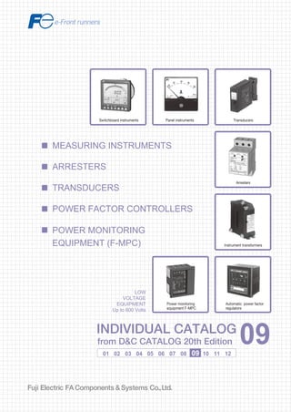
  • 1. Information in this catalog is subject to change without notice. 5-7, Nihonbashi Odemma-cho, Chuo-ku, Tokyo, 103-0011, Japan URL http://www.fujielectric.co.jp/fcs/eng INDIVIDUALCATALOGfromD&CCATALOG20thEdition 09 LOW VOLTAGE PRODUCTS Up to 600 Volts Individual catalog No. 01 Magnetic Contactors and Starters Thermal Overload Relays, Solid-state Contactors 02 Industrial Relays, Industrial Control Relays Annunciator Relay Unit, Time Delay Relays Manual Motor Starters and Contactors Combination Starters Pushbuttons, Selector Switches, Pilot Lights Rotary Switches, Cam Type Selector Switches Panel Switches, Terminal Blocks, Testing Terminals Molded Case Circuit Breakers Air Circuit Breakers Earth Leakage Circuit Breakers Earth Leakage Protective Relays Measuring Instruments, Arresters, Transducers Power Factor Controllers Power Monitoring Equipment (F-MPC) Circuit Protectors Low Voltage Current-Limiting Fuses 03 04 05 06 07 08 09 10 HIGH VOLTAGE PRODUCTS Up to 36kV 11 Disconnecting Switches, Power Fuses Air Load Break Switches Instrument Transformers — VT, CT D&C CATALOG DIGEST INDEX AC Power Regulators Noise Suppression Filters Control Power Transformers 12 Vacuum Circuit Breakers, Vacuum Magnetic Contactors Protective Relays Limit Switches, Proximity Switches Photoelectric Switches 01 02 03 04 05 06 07 08 09 10 11 12 LOW VOLTAGE EQUIPMENT Up to 600 Volts INDIVIDUAL CATALOG from D&C CATALOG 20th Edition 09INDIVIDUAL CATALOG from D&C CATALOG 20th Edition 09 MEASURING INSTRUMENTS POWER MONITORING EQUIPMENT (F-MPC) TRANSDUCERS POWER FACTOR CONTROLLERS ARRESTERS Panel instruments Transducers Arresters Instrument transformers Automatic power factor regulators Switchboard instruments Power monitoring equipment F-MPC 2010-09 PDF FOLS DEC2009
  • 2. Ha Noi Office: No. 95 - TT4, My Dinh Urban Area, My Dinh, Nam Tu Liem, Hanoi. Tel: (84 4) 3568 3740 Fax: (84 4) 3568 3741 Cambodia Office: #140, Room 1-B, St430, Sangkat Toul Tompuong II, Khan Chamkamon, PP. Tel: 855 2322 3635 Fax: 855 2322 3645 Head Office: No 88, Vinh Phu 40, Hoa Long, Vinh Phu, Thuan An, Binh Duong. Tel: (84 650) 37 37 619 Fax: (84 650) 37 37 620 1800 6547 THINK TOGETHER Nhà phân phối thiết bị điện công nghiệp hàng đầu Việt Nam T
  • 3. 09 Switchboard Instruments WM8N type ................................................................................................... 09/1 Power line multi-meters WE1MA................................................................. 09/10 F type ............................................................................................................. 09/23 C series .......................................................................................................... 09/32 WF series ....................................................................................................... 09/39 WH7 series .................................................................................................... 09/43 WT2AC .......................................................................................................... 09/55 CN232, 233 .................................................................................................... 09/57 CN226 ............................................................................................................ 09/60 CN227 ............................................................................................................ 09/62 CN2340, 2341 ................................................................................................ 09/70 General information ..................................................................................... 09/71 Through-type CT/CC3L ................................................................................. 09/72 CT with primary winding/CC3P .................................................................... 09/75 Through type CT/CC3M ................................................................................ 09/77 Split type CT/CC2 .......................................................................................... 09/82 Voltage transformers/CD32, 34 .................................................................... 09/84 Optional accessories..................................................................................... 09/85 Automatic power factor regulator QC06E and QC12E ................................ 09/86 General information ..................................................................................... 09/102 Multiple function protectors and controllers F-MPC60B, F-MPC30 ................................................................................ 09/103 Power monitoring unit F-MPC04, F-MPC04P, F-MPC04S ............................................................. 09/118 MCCB with ZCT and zero-phase CT ............................................................. 09/132 Current transformers CC2............................................................................. 09/134 Terminal relay RS16.................................................................................... 09/137 Connector terminal-block AU-CW21B1...................................................... 09/138 Page Transducers Measuring Instruments, Transducers Arresters, Power Factor Controllers Power Monitoring Equipment Arresters (Surge protective devices) Panel Instruments Instrument Transformers Power Factor Controllers Power Monitoring Equipment
  • 4. MINIMUM ORDERS Orders amounting to less than ¥10,000 net per order will be charged as ¥10,000 net per order plus freight and other charges. WEIGHTS AND DIMENSIONS Weights and dimensions appearing in this catalog are the best information available at the time of going to press. FUJI ELECTRIC FA has a policy of continuous product improvement, and design changes may make this information out of date. Please confirm such details before planning actual construction. INFORMATION IN THIS CATALOG IS SUBJECT TO CHANGE WITHOUT NOTICE.
  • 5. Fuji Electric FA Components & Systems Co., Ltd./D & C Catalog Information subject to change without notice 09/1 09 Switchboard Instruments WM8N type WM8N type wide-angle indicating switchboard instruments ■ Description WN8N-type meters are used in many industrial applications such as switchboards, supervisory panels, metal-clad switchgear and control desks. These are compact in size and easy to read. Scales have equal intervals and indicate through a 240° angle, a feature which distinguishes them from the conventional meters. Meters can be read at a distance, since instrument surfaces are protected by a non-reflecting glass and are not affected by reflections from room lighting . Ammeters are provided with an overload scale in red. These instruments comply with the requirements of JIS C1102 and are highly reliable. They can withstand a great deal of abuse in use because of their rugged construction. ■ Features • High accuracy External magnetic fields cannot influence readings. • Accuracy class: 1.5 • Easy-to-read long-scales and pointer- indications can easily be read from a distance. • 110 × 110mm and 80 × 80mm front frame sizes. • Auxiliary equipment such as shunt, impedance box and series resistor is available. 80mm square 110mm square ■ Ordering information Specify the following: 1. Type number (Ordering code) 2. Measuring range 3. Supply voltage and frequency 4. Connection (When connecting to VT or CT, specify VT ratio or CT ratio) For further information, see page 09/04. Meter Description 110mm square Type 80mm square Type AC ammeter For direct connection Measuring range 0 – 1A 0 – 3A 0 – 5A 0 – 10A 0 – 15A 0 – 20A 0 – 30A Extended range type (0–X–3X) 0 – 1 – 3A 0 – 3 – 9A 0 – 5 – 15A 0 – 10 – 30A 0 – 15 – 45A 0 – 20 – 60A – Operating principle RMS responding Moving iron WM8NAR3 (RMS responding) WM8NAS3 (Moving iron) WM8NAR6 (RMS responding) WM8NAS6 (Moving iron) For connection to CT CT ratio 5/5A 10/5A 15/5A 20/5A 30/5A 40/5A 50/5A 60/5A 75/5A 100/5A 150/5A 200/5A 300/5A 400/5A 500/5A 600/5A 750/5A 800/5A 1000/5A 1000/5A Measuring range 0 – 5A 0 – 10A 0 – 15A 0 – 20A 0 – 30A 0 – 40A 0 – 50A 0 – 60A 0 – 75A 0 – 100A 0 – 150A 0 – 200A 0 – 300A 0 – 400A 0 – 500A 0 – 600A 0 – 750A 0 – 800A 0 – 1000A 0 – 1kA Extended type (0–X–3X) 0 – 5 – 15A 0 – 10 – 30A 0 – 15 – 45A 0 – 20 – 60A 0 – 30 – 90A 0 – 40 – 120A 0 – 50 – 150A 0 – 60 – 180A 0 – 75 – 225A 0 – 100 – 300A 0 – 150 – 450A 0 – 200 – 600A 0 – 300 – 900A 0 – 400 – 1200A 0 – 500 – 1500A 0 – 600 – 1800A 0 – 750 – 2250A 0 – 800 – 2400A 0 – 1000 – 3000A 0 – 1kA – 3kA Power consumption 0.4VA 3VA Operating principle RMS responding Moving iron Power consumption 0.4VA 3VA
  • 6. Fuji Electric FA Components & Systems Co., Ltd./D & C Catalog Information subject to change without notice 09/2 Switchboard Instruments WM8N type Meter Description 110mm square Type (Ordering code) 80mm square Type (Ordering code) AC voltmeter DC voltmeter For direct connection Measuring range 0 – 50V 0 – 100V 0 – 150V 0 – 300V 0 – 600V WM8NVR3 (RMS responding) WM8NVS3 (Moving iron) WM8NVR6 (RMS responding) WM8NVS6 (Moving iron) WM8NAM3 (Moving coil) WM8NAM6 (Moving coil) DC ammeter For direct connection Measuring range 0 –1mA 0 – 3mA 0 – 5mA 0 – 10mA 0 – 30mA 0 – 50mA 0 – 100mA 0 – 1A 0 – 5A 0 – 10A 0 – 15A 0 – 30A 0 – 200A 0 – 250A 0 – 500A Operating principle: Moving coil type Internal resistance: 1mA: Approx. 185Ω 3mA: Approx. 17Ω 5mA: Approx. 10Ω 10mA and above: Approx. 50mV For connection to VT VT ratio 440/110V 3300/110V 6600/110V 6600/110V Measuring range 0 – 600V 0 – 4.5kV 0 – 9kV 0 – 9000V VT ratio:Y/110 (Y: VT primary voltage) For connection to shunt Measuring range 0 – 50A 0 – 75A 0 – 100A 0 – 150A Operating principle: Moving coil type Shunt ratings: 60mV For connection to series resistor Measuring range 0 – 750V 0 – 1kV 0 – 1.5kV 0 – 2kV Operating principle: Moving coil type Series resister: External Power consumption: 1mA 0 – 200V 0 – 300V 0 – 500V 0 – 600V For direct connection Measuring range 0 – 10V 0 – 30V 0 – 50V 0 – 100V 0 – 150V Operating principle: Moving coil type Series resister: Internal Internal resistance: 10V: 10kΩ 30V: 30kΩ 50V: 50kΩ 100V: 100kΩ 150V: 150kΩ WM8NVM3 (Moving coil) WM8NVM6 ((Moving coil)) Operating principle RMS responding Moving iron Power consumption 50V: 0.1V 100V: 0.1VA 150V: 0.9VA 300V: 1.8VA 600V: 1.2VA 8VA Operating principle RMS responding Moving iron Power consumption 0.9VA 8VA 200V: 200kΩ 300V: 300kΩ 500V: 500kΩ 600V: 600kΩ ■ Ordering information Specify the following: 1. Type number (Ordering code) 2. Measuring range 3. Supply voltage and frequency 4. Connection (When connecting to VT or CT, specify VT ratio or CT ratio) For further information, see page 09/04.
  • 7. Fuji Electric FA Components & Systems Co., Ltd./D & C Catalog Information subject to change without notice 09/3 09 Switchboard Instruments WM8N type Meter Description 110mm square Type 80mm square Type Frequency meter Measuring range 45 – 55Hz 110V 55 – 65Hz 110V 45 – 55Hz 220V 55 – 65Hz 220V Operating principle: Frequency/DC transducing type Power consumption: 1.5VA at 110V 1.5VA at 220V WM8NP13 WM8NP16 Single-phase 2-wire wattmeter For connection to VT and CT Measuring range 0 – ZkW Z= 0.5 x x Z: kWatt X: CT primary current Y: VT primary voltage Operating principle: Power/DC transducing type Power consumption (WM8NC03) Current coil: 1VA (at 5A) Voltage coil: 2VA (at 110V) Power consumption (WM8NC06) Current coil: 0.5VA (at 5A) Voltage coil: 1.7VA (at 110V) WM8NC03 WM8NC06 3-phase 3-wire wattmeter For connection to VT and CT Measuring range 0 – ZkW Z= x Z: kWatt X: CT primary current Y: VT primary voltage Operating principle: Power/DC transducing type Power consumption Current coil: 0.5VA per element (at 5A) Voltage coil: 1.7VA per element (at 110V) WM8NC23 WM8NC26 3-phase 4-wire wattmeter For connection to VT and CT Measuring range 0 – ZkW Z= x Z: kWatt X: CT primary current Y: VT primary voltage Operating principle: Power/DC transducing type Power consumption Current coil: 0.5VA per element (at 5A) Voltage coil: 0.8VA per element (at 110V) WM8NC33 WM8NC36 X 5 Y 110 X 5 Y 110 X 5 Y 110 X 5 Y 110 3-phase 3-wire varmeter For connection to VT and CT Measuring range 0 – Zkvar Z= x Z: kvar X: CT primary current Y: VT primary voltage Operating principle: Reactive power/DC transducing type Power consumption Current coil: 0.5VA per element (at 5A) Voltage coil: 1.7VA per element (at 110V) WM8NV23 WM8NV26 X 5 Y 110 3-phase 4-wire varmeter For connection to VT and CT Measuring range 0 – Zkvar Z= x Z: kvar X: CT primary current Y: VT primary voltage Operating principle: Reactive power/DC transducing type Power consumption Current coil: 0.5VA per element (at 5A) Voltage coil: 1.7VA per element (at 110V) WM8NV33 WM8NV36 3-phase 3-wire power factor meter (for balanced circuit) For connection to VT and CT VT ratio: = CT ratio: = Operating principle: Phase angle/DC transducing type Power consumption Current coil: 0.9VA (at 5A) Voltage coil: 0.6VA per phase (at 110V) WM8NA13 WM8NA16 Y 110 V X 5 A 3-phase 3-wire power factor meter (for unbalanced circuit) For connection to VT and CT VT ratio: = CT ratio: = Operating principle: Phase angle/DC transducing type Power consumption Current coil: 1.1VA per phase (at 5A) Voltage coil: 1.9VA per phase (at 110V) WM8NA23 WM8NA26 Y 110 V X 5 A 3-phase 4-wire power factor meter (for unbalanced circuit) For connection to VT and CT VT ratio: = CT ratio: = Operating principle: Phase angle/DC transducing type Power consumption Current coil: 1.1VA per phase (at 5A) Voltage coil: 0.8VA per phase (at 110V) WM8NA43 WM8NA46 Y 110 V X 5 A
  • 8. Fuji Electric FA Components & Systems Co., Ltd./D & C Catalog Information subject to change without notice 09/4 Switchboard Instruments WM8N type Type number nomenclature WM8N AR 3 - ALS 5YYY A Y Basic type Category AR : AC ammeter (including reception indicator) AS : AC ammeter (moving iron type only) VR : AC voltmeter (including reception indicator) VS : AC voltmeter (moving iron type only) AM : DC ammeter (moving coil type only) VM : DC voltmeter (moving coil type only) C0 : Single-phase, 2-wire wattmeter C1 : Single-phase, 3-wire wattmeter C2 : 3-phase, 3-wire wattmeter C3 : 3-phase, 4-wire wattmeter A0 : Single-phase, 2-wire power factor meter A1 : 3-phase power factor meter for balanced circuit A2 : 3-phase power factor meter for unbalanced circuit A4 : 3-phase, 4-wire power factor meter for unbalanced circuit P1 : Frequency meter V1 : Single-phase, 2-wire varmeter V2 : 3-phase, 3-wire varmeter V3 : 3-phase, 4-wire varmeter AT : 3-phase, 3-wire current power factor meter Additional specifications Y : None (standard specification) R : Setting pointer equipped (red) Z : The following additional specifications (Specify the content.) [Additional specifications] Single scale/double printing, double scale/double printing color line, color band, colored characters, meter installation orientation processing for transit through tropical areas Scale unit 1 : % 2 : m 3 : mm 4 : m3 /h 5 : Nm3 /h 6 : ppm 7 : rpm 8 : o C 9 : l/h A : A B : µA C : cos D : mA E : kA F : m3 /s G : min-1 H : Hz J : Mvar K : kvar L : var M : MPa N : kPa P : Pa Q : pH R : t/h S : MW T : kV U : mV V : V W : mg/l X : kW Y : x kV Z : Not given above. (Be sure to specify.) Scale numbers : Specify the scale numbers with four digits. Enter the specification from the left, and enter "Y" for any remaining digits.Enter "R" for a decimal point. If the scale unit is factored, specify the following at the end: S for x1000, H for x100, or T for x10. Example 1 : 500V Specify “500Y”. Example 2 : 5V Specify “5YYY”. Example 3 : 5.5V Specify “5R5Y”. Example 4 : 5kV Specify “5YYY”. Example 5 : 5000V Specify “5000”. Example 6 : 1000ppm Specify “1000”. Example 7 : 1 x 1000ppm Specify “1YYS”. Example 8 : 4.7 x 100ppm Specify “4R7H”. Example 9 : 4.7 x 10ppm Specify “4R7T”. Example 10 : ± scale Specify “ZZZZ” and specify the scale.For an extended scale, specify the effective scale range (standard scale portion). Example 11 : 10/5A times 3 extension Specify “10YY”. CS05 : Power factor meter 0.5 - 1 - 0.5 CST0 : Current power factor meter 0 - 1 - 0 - 1 - 0 HZYY : Frequency meter 01ML *3 : 0 - 1 - 0 (power factor linear scale) 01MN *3 : 0 - 1 - 0 (phase angle linear scale) 05ML *3 : 0.5 - 1 - 0.5 (power factor linear scale) 05MN *3 : 0.5 - 1 - 0.5 (phase angle linear scale) ZZZZ : Specifications not given above. (Be sure to specify the scale.) *3 Power factor display for DC ammeter and voltmeter (reception indicator). *1 If a CT or VT is used, be sure to specify the CT ratio or VT ratio.(If a power factor meter is used, the CT ratio or VT ratio does not have to be specified.) Also, if a power factor meter for an unbalanced circuit is used, be sure to specify the rated frequency. *2 Table of rated voltages : Can be produced, : Cannot be produced. Category Voltage between wires: 100V 110 to 220V 105 to 210V 100 to 200V Voltage between wires: 220V Single-phase, 2-wire wattmeter/ power factor meter Single-phase, 3-wire wattmeter 3-phase, 3-wire wattmeter 3-phase, 4-wire wattmeter 3-phase power factor meter for balanced circuit 3-phase power factor meter for unbalanced circuit 3-phase, 4-wire power factor meter Single-phase, 2-wire varmeter 3-phase, 3-wire varmeter 3-phase, 4-wire varmeter Rated Input AC ammeter (AC) *1 For direct connection Standard ALA : 0 to 1A ALJ : 0 to 3A ALS : 0 to 5A AMT : 0 to 10A AND : 0 to 15A ANG : 0 to 20A ANL : 0 to 30A 2 times A2Z : Order production 3 times A32 : 0 to 1A times 3 A34 : 0 to 3A times 3 A35 : 0 to 5A times 3 A36 : 0 to 10A times 3 A37 : 0 to 15A times 3 A38 : 0 to 20A times 3 A39 : 0 to 30A times 3 (moving iron type only) 5 times A52 : 0 to 1A times 5 A55 : 0 to 5A times 5 For CT connection Standard A41 : A/1A A42 : A/5A 2 times A43 : A/1A times 2 A44 : A/5A times 2 3 times A45 : A/1A times 3 A46 : A/5A times 3 5 times A47 : A/1A times 5 A48 : A/5A times 5 Special ZZZ : 0 to 100mA min. to 0 to 30A max. (Be sure to specify the input value.) AC voltmeter (AC) *1 For direct connection VNT : 0 to 50V VPK : 0 to 100V VPZ : 0 to 150V VRX : 0 to 300V VSJ : 0 to 600V For VT connection V12 : 0 to 150V V13 : 0 to 150/√3V Special ZZZ : 0 to 50V min. to 0 to 600V max. (Be sure to specify the input value.) Frequency meter Standard H10 : 110V 45 to 55Hz H11 : 110V 55 to 65Hz H12 : 110V 45 to 65Hz H20 : 220V 45 to 55Hz H21 : 220V 55 to 65Hz H22 : 220V 45 to 65Hz Special ZZZ : Specifications not given above. (Be sure to specify the input value.) Wattmeter, varmeter, and power factor meter *1 *2*4 Standard D13 : 110V/1A D14 : 110V/5A D15 : 220V/1A D16 : 220V/5A D20 : 110 to 220V/5A Special ZZZ : Specifications not given above. (Be sure to specify the input value.) DC ammeter (DC) Standard AFA : 0 to 1mA AFN : 0 to 3mA AFX : 0 to 5mA AGZ : 0 to 10mA AHM : 0 to 30mA AHY : 0 to 50mA AJR : 0 to 100mA AKG : 0 to 300mA AKM : 0 to 500mA ALA : 0 to 1A ALC : 0 to 1.5A ALE : 0 to 2A ALJ : 0 to 3A ALS : 0 to 5A AMT : 0 to 10A AND : 0 to 15A ANG : 0 to 20A ANL : 0 to 30A A04 : 0 to 60mV (for shunt) A05 : 0 to 100mV (for shunt) AHE : 4 to 20mA AHH : 4 to 25.3mA DEM : ±500µA D04 : ±60mV (for shunt) D08 : 0 to 100mV (for shunt, with VR) Special ZZZ : Be sure to specify an input value in the range of 0 to 300µA min. to 0 to 1A max. DC voltmeter (DC) Standard VLA : 0 to 1V VLJ : 0 to 3V VLS : 0 to 5V VMT : 0 to 10V VNL : 0 to 30V VNT : 0 to 50V VPB : 0 to 75V VPK : 0 to 100V VPZ : 0 to 150V VRL : 0 to 200V VRX : 0 to 300V VSF : 0 to 500V VSJ : 0 to 600V VLR : 1 to 5V V01 : For connection to external series resistor Special ZZZ : 0 to 50mV min. to 0 to 600V max. (Be sure to specify the input value.) *4 The rated voltage for the 3-phase, 4-wire type is the voltage between wires. Dimensions 3 : 110 x 110mm 6 : 80 x 80mm
  • 9. Fuji Electric FA Components & Systems Co., Ltd./D & C Catalog Information subject to change without notice 09/5 09 ■Dimensions, mm WM8NAS3, WM8NVS3, WM8NAR3, WM8NVR3, WM8NAM3, WM8NVM3, WM8NA13, WM8NP13, WM8NAT3 Switchboard Instruments WM8N type WM8N 6 WM8NC03, WM8NC13, WM8NC23, WM8NC33, WM8NV23, WM8NV33, WM8NA23, WM8NA43 Panel cutting 90±0.5 90±0.5 90±0.590±0.5 Panel cutting 21 ø99 110 110 15 Terminal cover M4 M5 90 12 10 90 Terminal cover M4 M5 90 12 10 90 4-ø6 21 ø99 110 110 15 97 4-ø6 * 90 ø101±0.5 ø101±0.5 * AC ammeter (WM8NAS3 type): 72 AC voltmeter (WM8NVS3 type): 99 Terminal cover M4 Panel cutting 64±0.5 64±0.5 M418 64 ø70 80 80 15 * 105 64 4-ø5.5 ø72±0.5 12 10 * AC ammeter (WM8NAS6): 72.5 AC voltmeter (WM8NVS6): 72.5 Type Rating A B C D E F G d Mass (kg) DM-5 3 to 5kV 170 120 110 154 170 140 106 4 1.0 or less DM-10 6 to 10kV 220 160 140 194 210 140 106 4 1.5 or less DM-15 12 to 15kV 290 210 200 248 264 190 146 5 2.0 or less DM-20 20kV 390 260 300 294 310 220 176 5 3.0 or less DM-25 25kV 500 330 400 356 372 280 236 5 3.5 or less • DC converter for WM8N 6 • Series resistor ø100 160 140 77 91 40 2 11-M4 2-ø6.5 3L P3 2S P1 P2 1S 1L 2L 3S 99 – + DM-5 to 25 DM-1 DM-2 73 48.52-M4 4-ø8 E D 2-M5 B C A 36 52 44 2-ø3.5 36 G F ød 2.5 2.5 2-ø5 100 110 124 52 36 4 3-M5 53 6 M(+)M(–) E + kV M (–) M (+) E + kV
  • 10. Fuji Electric FA Components & Systems Co., Ltd./D & C Catalog Information subject to change without notice 09/6 ■ Wiring diagrams Switchboard Instruments WM8N type Load Load Load Load Load Load Load Load Load Load Load Load K k L CT AC ammeter DC ammeter DC voltmeter Frequency meter AC voltmeter For connection CT For connection VT For connection shunt For connection WM8NVS6 type U u V v VT Series resistor Series resistor Series resistor (WM8NVS6 only) Shunt Shunt extension lead (0.06Ω) + – + – + – + – + – + – + – + – + – + – +kV Series resistor M (+) M (-) U u V v VT
  • 11. Fuji Electric FA Components & Systems Co., Ltd./D & C Catalog Information subject to change without notice 09/7 09 Switchboard Instruments WM8N type Wattmeter: WM8NC06 Varmerter: WM8NV16 Wattmeter: WM8NC26 Varmerter: WM8NV26 Wattmeter: WM8NC36 Wattmeter: WM8NC03 Varmerter: WM8NV13 Wattmeter: WM8NC13 Wattmeter: WM8NC23 Varmerter: WM8NV23 Wattmeter: WM8NC33 Varmerter: WM8NV36 Wattmeter: WM8NV33 Wattmeter: WM8NC16 Load Load Load Load Load Load 1 2 VT K k L U u V v CT Converter Converter Converter Converter Converter Load Load Load Load 1S 1L P1 P2 + – 1S 1L 3S 3L P3P2P1 1 2 3 VT K k L K k L U u V v U u V v CT + − 1 2 3 1 2 3 1 2 3 0 −+ −+ −+ −+ VT K k L K k L U u V v U u V v CT P1 P2 P3 1S 1L 3S 3L + − VT 1L 2S 2L1S 1 2 10 6 3 8 9 5 7 P3P1 P0 3S 3L K k L K k L K k L U u V v U u V v 1 2 3 0 CT 1S 1L 3S 3L P3P0P1 2S 2L K k L K k L K k L U u V v U u CT + − 1 2 5 7 A B C D 8 9 6 3 4 K k L K k L U u V v U u V v CT V1 1S 1 3 5 2 4 6 7 1L 3S 3L P3P2P1 K k L U u V v 1 2 CT VT 1S P1 1 2 3 4 P2 1L 1 1 2 5 7 A B C D 8 9 6 3 4 1 2 5 7 A B C D 8 9 6 3 4 1 2 5 7 A B C D 8 9 6 3 4 1 2 3 K k L K k L U u V v U u V v CT VT P1 P2 P3 3L3S1L1S 1 3 5 7 642 3 VT u v 0 U V uvu v UVU V P2P1 P3 + 3S – 1L1S 2S2L k 3L l 1 2 K CT k K k l K l L L L + – 0 u U VT u v uv U V UV 2S P2 v P1 1L1S V P3 3L2L3S 2 3 1 K L k k l K CT l k K L L l Meter Meter Meter Meter Meter
  • 12. Fuji Electric FA Components & Systems Co., Ltd./D & C Catalog Information subject to change without notice 09/8 Switchboard Instruments WM8N type Power foctor meter: WM8NA06, 03 Power foctor meter: WM8NA16, 13 Power foctor meter: WM8NA26 Power foctor meter: WM8NA23 Power foctor meter: WM8NA46 Power foctor meter: WM8NA43 K L VT u U 2 1 1S 1L P2 P1 v V k l Load Load CT K L VT u U 2 3 1 1S 1L P2 P3 v V k l CT Load Load lk P3 VT vu 3 2 U V P2P1 u v VU – 1S 1L 3S + k K 3L l L –+ 1 CT K L Convertor Convertor Meter Meter 1 LK P3 3S VT u v U V 2 3 1S 1L P1 P2 u U v V k l K k 3L Load L l CT 0 P3 U u U VT u V v V U v u V v 2S P2P1 1S1L – P0 2L3S + 3L 1 3 2 K k k l l K k L CT K L L l + – P3 vu U V vu v u P2 2S P1 1L1S P0 2L 3S UVU V Kk k l K k l L 3L L l K L 1 0 VT 3 2 CT
  • 13. Fuji Electric FA Components & Systems Co., Ltd./D & C Catalog Information subject to change without notice 09/9 09 Shunt WM9N-1, -2  Features • Shunt for DC ammeter. JIS (JIS C-1721) class 0.5 and class 1.0 models are available. Select the model based on the required accuracy. • Keep in mind that a shunt is a source of heat generation, and select a shunt with a current value with sufficient margin. (As a general rule, select a shunt with approximately 1.5 times the continuous operating current.) • The standard terminal voltage for the shunt is 60mV, but models with voltage of 100 mV can also be produced.  Connection wires Use a round-trip resistance of 0.06Ω for the shunt connection conductors. The same applies for class 1.0 models without connection wires. One-way length (m) 2 3 5.5 9 12.5 22 35 Cross-section area (mm2 ) 1.25 2 3.5 5.5 8 14 22 • 1 to 4A (with base) • 5 to 50A (with base) • 60 to 200A (with base) • 250 to 600A (no base) • Dimensions, mm Current A B C D E T 250•300A 110 130 30 36 M10x30 4 400A 110 140 40 36 M12x35 5 500A•600A 120 160 40 41 M12x35 6  Functions and specifications Item Applicable meter JIS Class 0.5 (JIS C-1721) JIS Class 1.0 (JIS C-1721) Shunt rating Shunt base / no base Type Shunt rating Shunt base / no base Type Shunt DC shunt Shunt connection items 60mV 1A With base WM9N-1 60mV 1A With base WM9N-2 2A 2A 3A 3A 4A 4A 5A 5A 7.5A 7.5A 10A 10A 15A 15A 20A 20A 30A 30A 40A 40A 50A 50A 60A 60A 75A 75A 100A 100A 150A 150A 200A 200A 250A No base 250A No base 300A 300A 400A 400A 500A 500A 600A 600A Note 1: Only one meter and can be connected to each shunt. Shunt (with base) (AF96-423) Shunt (no base) (AF96-423) Shunt (no base) (AF96-423)  Dimensions, mm 36 44 52 Two, 3.5-dia. holes 2-M4 screws 36 36 46 4 45 120 140 2-M6 screws2-M4 screws 25 6 18 33 5.5 10.5 45 120 140 2-M8 bolts2-M4 screws 25 6 18 43 (36)* 5.5 10.5 * ( ) 60 to 100A 45 A B E T 2-M4 screws4 DC Switchboard Instruments WM8N type
  • 14. Fuji Electric FA Components & Systems Co., Ltd./D & C Catalog Information subject to change without notice 09/10 Switchboard Instruments Power line multi-meters WE1MA power line multi-meters  Description Perform measurement and monitoring for 213 points in 52 categories for Single-phase/2-wire, Single-phase/3-wire, 3-phase/3-wire, and 3-phase/4-wire  Features • With one unit, you can measure or monitor the voltage, current, demand current, power, demand power, reactive power, apparent power, power factor, frequency, leakage current, harmonic effective value (A,V), distortion, harmonic content rate, power level, and reactive power level. • The unit supports 3-phase/3-wire, Single-phase/3-wire, and Single-phase/2-wire and switching to 3-phase/4-wire is supported with 2VT, 3CT/3VT, or 3CT settings. • The measurements are displayed using a four-element display: one display on the main monitor and three displays on the sub-monitors along with a bar graph. • Measure and output alarms for leakage current.  Types and ratings Measurement Input specifications Type Input circuits Input range Current (max. demand, demand, instantaneous), power (max. demand, demand, instantaneous), voltage, power factor, frequency, reactive power, power level, reactive power level, harmonic effective value, distortion, and harmonic content rate Single-phase/2-wire, Single-phase/3-wire, 3-phase/3-wire or all common 150V/300V, 5A WE1MA-A F -000 150V, 5A WE1MA-A 1 -000 300V, 5A WE1MA-A 3 -000 5A WE1MA-A 5 -000 150V WE1MA-A 9 -000 300V WE1MA-A A -000 150V/300V, 1A WE1MA-A G -000 150V, 1A WE1MA-A 2 -000 300V, 1A WE1MA-A 4 -000 1A WE1MA-A 6 -000 Current (max. demand, demand, instantaneous), power (max. demand, demand, instantaneous), voltage, power factor, frequency, reactive power, power level, reactive power level, harmonic effective value, distortion, harmonic content rate, and leakage current Single-phase/2-wire + leakage current, Single-phase/3-wire + leakage current 3-phase/3-wire+leakege current or all common 150/300V, 5A WE1MA-A F -000 150V, 5A WE1MA-A 1 -000 300V, 5A WE1MA-A 3 -000 5A WE1MA-A 5 -000 150V WE1MA-A 9 -000 300V WE1MA-A A -000 150/300V, 1A WE1MA-A G -000 150V, 1A WE1MA-A 2 -000 300V, 1A WE1MA-A 4 -000 1A WE1MA-A 6 -000 Type given above and ZCT50A Type given above and ZCT100A Type given above and ZCT200A Type given above and ZCT400A Type given above and ZCT600A Type given above and ZCT100A (outdoor) Current (max. demand, demand, instantaneous), power (max. demand, demand, instantaneous), voltage, power factor, frequency, reactive power, apparent power, power level, reactive power level, harmonic effective value, distortion, and harmonic content rate 3-phase, 4-wire 150/√3V or 300/√3V common, 5A WE1MA-A4F -000 150/√3V, 5A WE1MA-A41 -000 300/√3V, 5A WE1MA-A43 -000 5A WE1MA-A45 -000 150/√3V, 5A WE1MA-A49 -000 300/√3V, 5A WE1MA-A4A -000 150/√3V or 300/√3V common, 1A WE1MA-A4G -000 150/√3V, 1A WE1MA-A42 -000 300/√3V, 1A WE1MA-A44 -000 1A WE1MA-A46 -000 440/√3V, 5A WE1MA-A4B -000 440/√3V, 1A WE1MA-A4C -000 WE1MA • Outputs include four analog circuits, a pulse output, an alarm output, a CPU error output, and a communications output (according to specification). • Communications output supports F-MPC Net, CC-Link, AnyWire, Modbus RTU, and RS-485 (according to user specification). • All models comply with the RoHS Directive (i.e., lead-free).
  • 15. Fuji Electric FA Components & Systems Co., Ltd./D & C Catalog Information subject to change without notice 09/11 09 Switchboard Instruments Power line multi-meters Type number nomenclature WE1MA - □ □ □ □ □ - □ □ □ Basic type Hardware model B : Back light Green E : Back light White Input circuits F : Single-phase/2-wire, Single-phase/3-wire, and 3-phase/3-wire common 1 : Single-phase, 2-wire 2 : Single-phase, 3-wire 3 : 3-phase, 3-wire G : Single-phase/2-wire, Single-phase/3-wire, 3-phase/3-wire + leakage current common 5 : Single-phase, 2-wire + leakage current 6 : Single-phase, 3-wire + leakage current 7 : 3-phase, 3-wire + leakage current 4 : 3-phase, 4-wire Auxiliary power supply 1 : 85 to 264V AC or 80 to 143V DC 2 : 20 to 56V DC Analog output or communications output 0 : None Four analog output circuits 1 : 4 to 20mA DC 2 : 0 to 1mA DC 3 : 1 to 5V DC 4 : 0 to 5V DC 5 : 0 to 10V DC Communications output F : F-MPC Net A : RS-485 L : CC-Link M : Modbus RTU W : AnyWire Contact outputs 0 : None 1 : Pulse + alarm 2 : Alarm x 2 3 : Pulse x 2 4 : Pulse + CPU error 5 : Alarm + CPU error External operation input 0 : None 1 : 2 circuits LCD viewing direction 1 : Upper mounting (viewed from below) 2 : Lower mounting (viewed from above) Input range F : 150V, 300V common, 5A 1 : 150V, 5A 3 : 300V, 5A 5 : 5A 9 : 150V A : 300V G : 150V, 300V common, 1A 2 : 150V, 1A 4 : 300V, 1A 6 : 1A 7 : 5A (3-phase, 3-wire, 3CT) 8 : 1A (3-phase, 3-wire, 3CT) P : 150V, 5A (3-phase, 3-wire, 2VT, 3CT) Q : 150V, 1A (3-phase, 3-wire, 2VT, 3CT) R : 300V, 5A (3-phase, 3-wire, 2VT, 3CT) S : 300V, 1A (3-phase, 3-wire, 2VT, 3CT) 3-phase, 4-wire F : 150/√3V or 300/√3V, 5A 1 : 150/√3V, 5A 3 : 300/√3V, 5A 5 : 5A 9 : 150/√3V A : 300/√3V G : 150/√3V or 300/√3V, 1A 2 : 150/√3V, 1A 4 : 300/√3V, 1A 6 : 1A B : 440/√3V, 5A C : 440/√3V, 1A Z : Depends on user specification.
  • 16. Fuji Electric FA Components & Systems Co., Ltd./D & C Catalog Information subject to change without notice 09/12 Switchboard Instruments Power line multi-meters Specifications and performance Standard specifications and performance Item Specification Measurements Measurement Display error Output error Measurement Display error Output error Voltage (34 ranges) ±1.0% ±0.5% nth harmonic effective value Voltage, current ±1.5% ±1.5% Current (76 ranges) ±1.0% ±0.5% nth harmonic content rate Voltage ±1.0% ±2.5% Power ±1.0% ±0.5% Current ±2.5% ±2.5% Reactive power ±1.0% ±0.5% 5th harmonic conversion effective value Voltage, current ±1.5% ±1.5% Apparent power *1 ±1.0% ±0.5% 5th harmonic conversion effective value Voltage ±1.0% ±2.5% Power factor ±2.0% ±2.0% Current ±2.5% ±2.5% Frequency ±0.5% ±0.5% Power level Power factor of 1 ±2.0% ±2.0% Leakage current Io method, Igr method ±2.5%*2 ±2.5%*2 Power factor of 0.5 ±2.5% ±2.5% Reactive power level Power factor of 1 ±2.5% ±2.5% Fundamental wave effective value Voltage ±1.5% ±1.5% Reactive power level Power factor of 0.87 ±2.5% ±2.5% Current ±1.5% ±1.5% *1 For 3-phase/4-wire only *2 Error for ZCT is not included. It is ± 0.0025A (ZCT primary) at a leakage current detection sensitivity current of 0.1A max. Distortion Voltage ±1.0% ±2.5% Current ±2.5% ±2.5% Time limit setting Demand current 0s, 5s, 10s, 20s, 30s, 40s, 50s, 1min, 2min, 3min, 4min, 5min, 6min, 7min, 8min, 9min, 10min, 15min, 20min, 25min, 30min (95% time limit)Demand power Harmonic measurement Average time limit: 0min, 1min, 2min, 5min, 10min, 15min, 30min (average measurement) Bar graph error ±10% (% of span) Temperature effect 23±10°C permissible differential Conforming standards JIS C 1102-1, -2, -3, -4, -5, -7(1997), JIS C 1111(1985), JIS C 1216(1995), JIS C 1263(1995), JIS C8374(1991), EIA standard RS-485 Display refresh time Approx. 1s (approx. 0.25s for a bar graph) (For current leakage measurement, the refresh time is 2s max. for the digital display and the bar graph and 10s for the digital display and the bar graph for harmonic measurement.) Display elements and composition Liquid crystal display Main monitor Character height: 11mm, 5 digits Sub-monitor on left Character height: 6mm, 4 digits Sub-monitor in center and on right Character height: 6mm, 5 digits Bar graph 20 dots LCD viewing angle Standard item Upper mounting (viewed from below): top: 10°, bottom: 60°, left/right: 60° Special items Lower mounting (viewed from above): top: 60°, bottom: 10°, left/right: 60° Backlight LED backlight: Green or White, always ON, automatically turns OFF (after 5min with no operation), can be set to always OFF. Input power consumption (VA) Voltage circuit 0.2VA max. Current circuit 0.1VA max. (5A, 1A) Overload resistance Voltage circuit 2 x rated voltage for 10s, 1.2 x rated current for continuous Current circuit 40 x rated voltage for 1s, 20 x rated current for 4s, 10 x for 16 s, 1.2 x rated current for continuous Power supply power 1.5 x rated voltage for 10s, 1.2 x rated current for continuous, 1.5 x rated voltage for 10s at 110V DC, 1.3 x rated voltage for continuous at 110V DC Insulation resistance JIS C 1102-1 JIS C 1111 Between electrical circuits and external cabinet (ground) 50MΩ min. with 500V DC tester Between inputs, outputs, and auxiliary power supply Between outputs (analog, communication, pulse, or alarm) Between pulse outputs Between alarm outputs Analog outputs (negative common) are not isolated. Withstand voltage JIS C 1102-1 JIS C 1111 Between electrical circuits and external cabinet (ground) 2000V AC (50/60Hz), 1min. Between inputs, outputs, and auxiliary power supply Between outputs (analog, communication, pulse, or alarm) 1500V AC (50/60Hz), 1min. Between pulse outputs Between alarm outputs Analog outputs (negative common) are not isolated. Impulse withstand voltage JIS C 1111 Between auxiliary power supply and cabinet (ground) (only with leakage current measurement) 7kV, 1.2/50µs, positive and negative polarity, three times each Between electrical circuits (except analog outputs and communications outputs) and cabinet (ground) 6kV, 1.2/50µs, positive and negative polarity, three times each Between analog outputs or communications outputs and cabinet (ground) 5kV, 1.2/50µs, positive and negative polarity, three times each
  • 17. Fuji Electric FA Components & Systems Co., Ltd./D & C Catalog Information subject to change without notice 09/13 09 Switchboard Instruments Power line multi-meters Item Specification Analog outputs No. of outputs 4 circuits Output specifications 4 to 20mA DC (550Ω max.) 0 to 5V/1 to 5V DC (600Ω min.) 0 to 10V DC (2kΩmin.) 0 to 1mA DC (10kΩ max.) Specify any one of the above. Supported output elements Voltage (RS-ST-TR), current (R-S-T), demand current (R-S-T), power, demand power, reactive power, apparent power, power factor, frequency, leakage current, distortion, fundamental wave effective value, 5th harmonic conversion content rate (automatic switching to maximum phase A or V), 5th harmonic conversion effective value, nth harmonic content rate, nth harmonic effective value (for phases A and V) Response time 1s max. (time until ±1% of the last steady value is reached), Harmonic measurement: 10s max., Current leakage measurement: 2s max. Output ripple Maximum of 2 x inherent error (% of output span) Outputs are not isolated (negative common). Pulse output*4 Power level or reactive power level Output method: Optical MOS-FET SPST-NO relay Contact capacity: AC/DC 125V, 70mA (resistive load/inductive load) Pulse width: 250±10ms (100 to 130ms depending on range setting and output pulse unit setting) The output pulse unit can be set in the following ranges. The output pulse unit will not change even if the measurement range is changed. • 3-phase/3-wire, 3-phase/4-wire: Full load power (kW, kvar) = √ 3 x Rated voltage (V) x Rated current (A) x 10-3 • Single-phase/3-wire: Full load power (kW, kvar) = 2 x Rated voltage (V) x Rated current (A) x 10-3 • Single-phase: Full load power (kW, kvar) = Rated voltage (V) x Rated current (A) x 10-3 Full load power (kW, kvar) Output pulse unit (kWh (kvarh)/pulse) Multiplying factor Less than 1 0.1 0.01 0.001 0.0001 0.01*3 1 min. to less than 10 1 0.1 0.01 0.001 0.1 10 min. to less than 100 10 1 0.1 0.01 1 100 min. to less than 1,000 100 10 1 0.1 10 1,000 min. to less than 10,000 1,000 100 10 1 100 10,000 min. to less than 100,000 10,000 1,000 100 10 1,000 100,000 min. to less than 1,000,000 100,000 10,000 1,000 100 10,000 Alarm output *4 Alarm elements: Set any of the following: demand current, demand power, leakage current, 5th harmonic conversion content rate, nth harmonic content rate, distortion, voltage, alarm OFF. Reset method: Automatic reset or manual reset (setting) Contact delay time: 0 to 300s (1s steps) Output contacts: No-voltage NO (OR output of each phase) Contact capacity: 250V AC 8A, 125V DC 0.3A (resistive load), 250V AC 2A, 125V DC 0.1A (inductive load) Alarm elements Item Specification Demand current Function Alarm display and alarm output when demand measurement value ≥ upper-limit set value Setting accuracy ±1.0% (% of full scale) Setting range 5% to 100% of max. scale value (1% steps) Demand power Setting accuracy ±1.0% (% of full scale) Setting range 5% to 100% of max. scale value (1% steps) Leakage current (only with leakage current management) Sensitive current Greater than 50% to 100% of rated sensitive current Rated sensitive current 0.03A/0.05A/0.1A/0.2A/0.4A/0.8A Operation time Time delay type (greater than 0.1s to 2s max.) Test function Detection of leakage current can be tested in test mode. 5th harmonic conversion content rate nth harmonic content rate Distortion Function Alarm display and alarm output (detection at maximum phase) when measurement value ≥ Upper-limit set value Setting accuracy Current: ±2.5%, Voltage: ±1.0%, as percentage of content rate Setting range Current 5th harmonic conversion content rate, nth harmonic content rate (n = 3, 4, 5, 7, 9, 11, 13, or 15), distortion 5% to 100% (1% steps) Voltage 5th harmonic conversion content rate, nth harmonic content rate (n = 3, 4, 5, 7, 9, 11, 13, or 15), distortion 5% to 20% (0.1% steps) Detection characteristics Average value mode: Detection when the average measurement value exceeds the setting given above Inverse time limit mode: Detection according to inverse time limit characteristics of instantaneous value (only for 5th harmonic conversion content rate) Voltage Function Alarm display and alarm output (detection for maximum phase) when measurement value ≥ upper-limit set value Alarm display and alarm output (detection for minimum phase) when measurement value ≥ lower-limit set value Setting accuracy ±1.0% (with full scale as 150%) Setting range 30% to 150% (1% steps) with full scale as 150% CPU error output *4 Detection item (self-diagnosis item), OR output of detection items Contact configuration Capacity (1) Watchdog timer (internal and external), (2) RAM check error, (3) A/D conversion error OR output of detection items NC contact 250V AC 5A, 125V DC 0.2A (resistive load), 250V AC 1.5A (inductive load) * 3 The multiplying factor is 0.01, but 0.1 is displayed for the multiplying factor. (Four digits are displayed for the integer portion, and four digits are displayed below the decimal point for the expanded display.) * 4 A combination of two of the following outputs can be used: pulse output, alarm output, and CPU error output (only one CPU error output can be used).
  • 18. Fuji Electric FA Components & Systems Co., Ltd./D & C Catalog Information subject to change without notice 09/14 Switchboard Instruments Power line multi-meters Item Specification External operation input No. of inputs 2 circuits and functions (4 types) switchable using settings External reset The alarm output or maximum/minimum value can be reset by adding an external voltage signal. Alarm output reset and maximum/minimum value reset can be switched using settings. The input has the same ratings as the auxiliary power supply. External display switching The display can be switched by adding an external voltage signal. Measurement element switching and phase switching can be set. The input has the same ratings as the auxiliary power supply. Minimum operation pulse width: 300ms continuous application supported (1) 100/110V AC 0.4 VA, 200/220V AC 1.4VA, 100/110V DC 0.4W, Accepts both AC and DC. Contact capacity: Approx. 3mA (100/110V AC/DC), approx. 6mA (200/220V AC) (2) 24V DC 0.3W, 48V DC 1.2W, Contact capacity: Approx. 10mA (24 V DC), approx. 20mA (48V DC) Vibration and shock resistance JIS C 1102-1 JIS C 0040, 0041 Vibration: 0.15mm single amplitude, 10 to 55Hz, 1 octave per minute for 5 sweeps Shock: 490m/s2, three times each in X, Y, and Z directions Operating temperature and humidity range −10 to 55°C, 30% to 85% RH (no condensation) Storage temperature range −25 to 70°C Communications specification Item Specification F-MPC Net Standard EIA RS-485 (1983) Cable length 1000m (total length) Transmission method 2-wire half-duplex Address 1 to 99 and not used (Loc) Synchronization method Asynchronous No. of connectable units Up to 31 units per system (including other devices) Transmission speed 4800/9600/19200bps RS-485 communications output RS-485, 2-wire half-duplex, asynchronous Cable length 1000m (total length) Transmission speed 1200/2400/4800/9600/19200bps Address 1 to 254 (31 units max. can be connected) Modbus RTU communications output Standard EIA RS-485 Cable length 1000m (total length) Synchronization method Asynchronous Address 1 to 247 (31 units max. can be connected) Transmission speed 4800/9600/19200/38400bps CC-Link Ver.1.10 Transmission speed 156k/625k/2.5M/5M/10Mbps No. of allocated stations 1 remote device station allocated Maximum transmission distance 1200m(156kbps) / 900m(625kbps) / 400m(2.5Mbps) / 160m(5Mbps) / 100m(10Mbps) No. of connectable units 42 (if only this unit is used) AnyWire Full quadruplex or full duplex total frame cyclic communications Protocol AnyWireBus protocol Address settings 0 to 63 (full quadruplex), 0 to 15 (full duplex) Transmission speed Full quadruplex: 7.8kHz (1km), 15.6kHz (500m), 31.3kHz (200m), 62.5kHz (100m) Full duplex: 7.8kHz (1km), 31.3kHz (200m) The values in parentheses are the maximum overall cable extension lengths. No. of connectable units Full quadruplex: 64, Full duplex: 16 • Communications specifications ■ Measurement range • Voltage measurement range (34 ranges) 150.0V 150V 300.0V 300V 500V 600V 600V 600V 1200V 1500V 2400V 3000V 3.00kV 4500V 4.50kV 9000V 9.00kV 15.00kV (110V) (110V) (220V) (220V) (380V) (440V) (460V) (480V) (880V) (1100V) (1650V) (2200V) (2200V) (3300V) (3300V) (6600V) (6600V) (11kV) 18.00kV 18.00kV 24.00kV 25.00kV 30.0 kV 45.0 kV 90.0 kV 120.0 kV 150.0 kV (13.2kV) (13.8kV) (16.5kV) (18.4kV) (22kV) (33kV) (66kV) (77kV) (110kV) 180.0kV 210.0kV 270.0kV 300.0kV 400.0kV 500.0kV 750.0kV (132kV) (154kV) (187kV) (220kV) (275kV) (380kV) (550kV) • Current measurement range (76 ranges) 5.00A 6.00A 7.50A 8.00A 10.00A 10.0A 12.00A 12.0A 15.00A 15.0A 20.00A 20.0A 25.00A 25.0A 30.00A 30.0A 40.0A 50.0A 60.0A 75.0A 80.0A 100.0A 100A 120.0A 120A 150.0A 150A 200.0A 200A 250.0A 250A 300.0A 300A 400A 500A 600A 750A 800A 900A 1000A 1.00kA 1200A 1.20kA 1500A 1.50kA 1600A 1.60kA 1800A 1.80kA 2000A 2.00kA 2500A 2.50kA 3000A 3.00kA 4000A 4.00kA 5000A 5.00kA 6000A 6.00kA 7500A 7.50kA 8000A 8.00kA 9.00kA 10.00kA 10.0kA 12.00kA 12.0kA 15.00kA 15.0kA 20.00kA 20.0kA 30.00kA 30.0kA • Current display sensitivity: Sets the full scale of the current meter. The sensitivity can be set to between 40% and 120% of the CT ratio.
  • 19. Fuji Electric FA Components & Systems Co., Ltd./D & C Catalog Information subject to change without notice 09/15 09 Switchboard Instruments Power line multi-meters • Power (apparent power range) 480W to 1000MW range selection, maximum scale setting 40 to 115% • Reactive power LEAD, LAG360var to 1000Mvar range selection, maximum scale setting 30% to 115% • Power factor LEAD0.5 to 1 to LAG0.5 or LEAD0 to 1 to LAG0 range selection • Frequency 45 to 55Hz or 55 to 65Hz, 45 to 65Hz range selection ■ Part names and functions S SET This switch is used to toggle between a normal display (five integer digits) and an expanded display (two integer digits and three digits below the decimal point) for the total value of each power level. After the display is switched, it will return to a normal display if there is no operation for 10 minutes. The switch can also be used to switch into setting mode. When the switch is pressed for 3s or longer, the mode will switch to setting mode. In setting mode, the switch is used to enter set values. Use this switch to reset alarms. The switch can also be used to reset maximum and minimum values for display of maximum and minimum measurements. In setting mode, the switch is used to move between setting items. RESET/ SHIFT DISPLAY MAX/MIN MODE Scale numbers This is automatically set using the measurement range setting. Upper limit or lower limit setting index This displays the set value of the upper limit or lower limit. Unit display This is automatically set using the measurement range setting. Phase display Multiplying factor display The multiplying factor is displayed in the lower right part of the main monitor when power level and reactive power level are displayed. Use this switch to toggle the phase display (between wires) for current (or voltage). After the display is switched, it will return to the origi- nal phase display (between wires) if there is no operation for 10 minutes. In setting mode, the switch is used to end setting mode. Use this switch to switch the measurement display elements for the main monitor. After the display is switched, it will return to the origi- nal measurement display element if there is no opera- tion for 10 minutes. In setting mode, the switch is used to change set values. Use this switch to toggle between the normal mea- surement display and the maximum/minimum mea- surement display. Use this switch to toggle between normal measure- ment display and harmonic (voltage/current) display. In setting mode, the switch is used to switch setting items. – + Bar graph display Analog display of measurement value on main monitor (Settings can be made for bar graph display of the measurement value on the sub-monitor.) Digital display Four elements can be measured and monitored at the same time. • Main monitor • Sub-monitor on right • Sub-monitor in center • Sub-monitor on left
  • 20. Fuji Electric FA Components & Systems Co., Ltd./D & C Catalog Information subject to change without notice 09/16 Switchboard Instruments Power line multi-meters ■ Wiring diagrams • Single-phase/2-wire, Single-phase/3-wire, 3-phase/3-wire *4 (1) Single-phase, 2-wire (2) Single-phase, 3-wire (3) 3-phase, 3-wire (2VT, 2CT) (4) 3-phase, 3-wire (2VT, 3CT) (5) Current input 3-phase, 3-wire (2CT) (6) Current input 3-phase, 3-wire (3CT) 1 2 5 6 7 8 9 12 13 17 16 18 20 22 24 26 28 19 21 23 25 27 29 1 2 5 6 7 8 9 10 12 13 14 15 17 16 18 20 22 24 26 28 19 21 23 25 27 29 RS LOAD *1 *2 External operation input 1 External operation input 2 Auxiliary power supply Auxiliary power supply Auxiliary power supply Auxiliary power supply Auxiliary power supply Auxiliary power supply CT VTU V K L u k v Analog output 1 Analog output 2 Analog output 3 Analog output 4 Contact output 1 Contact output 2 *1 *3 *1 *2 External operation input 1 External operation input 2 *1 *2 External operation input 1 External operation input 2 *1 *2 External operation input 1 External operation input 2 *1 *2 External operation input 1 External operation input 2 *1 *2 External operation input 1 External operation input 2 Analog output 1 Analog output 2 Analog output 3 Analog output 4 Contact output 1 Contact output 2 *1 *3 Analog output 1 Analog output 2 Analog output 3 Analog output 4 Contact output 1 Contact output 2 *1 *3 Analog output 1 Analog output 2 Analog output 3 Analog output 4 Contact output 1 Contact output 2 *1 *3 Analog output 1 Analog output 2 Analog output 3 Analog output 4 Contact output 1 Contact output 2 *1 *3 Analog output 1 Analog output 2 Analog output 3 Analog output 4 Contact output 1 Contact output 2 *1 *3 RNT LOAD + – + – + – + – + – + – + – + – + – + – + – + – + – + – + – + – CT K L k K L k 1 2 5 6 7 8 9 10 12 13 14 15 17 16 18 20 22 24 26 28 19 21 23 25 27 29 1 2 3 4 5 6 7 8 9 10 12 13 14 15 17 16 18 20 22 24 26 28 19 21 23 25 27 29 VTU V u v U V u v RST LOAD CT K L k K L k VTU V u v U V u v RST LOAD CT K L k K L k K L k 1 2 5 6 7 12 13 14 15 17 16 18 20 22 24 26 28 19 21 23 25 27 29 1 2 3 4 5 6 7 12 13 14 15 17 16 18 20 22 24 26 28 19 21 23 25 27 29 RST LOAD + − + − + − + − CT K L k K L k RST LOAD + − + − + − + − CT K L k K L k K L k
  • 21. Fuji Electric FA Components & Systems Co., Ltd./D & C Catalog Information subject to change without notice 09/17 09 Switchboard Instruments Power line multi-meters (7) Single-phase, 3-wire (8) Single-phase, 2-wire (9) Voltage input 3-phase, 3-wire (11) Voltage input Single-phase, 2-wire (10) Voltage input Single-phase, 3-wire Auxiliary power supplyAuxiliary power supply *1 *2 External operation input 1 External operation input 2 *1 *2 External operation input 1 External operation input 2 *1 *2 External operation input 1 External operation input 2 *1 *2 External operation input 1 External operation input 2 *1 *2 External operation input 1 External operation input 2 Analog output 1 Analog output 2 Analog output 3 Analog output 4 Contact output 1 Contact output 2 *1 *1 *3 Analog output 1 Analog output 2 Analog output 3 Analog output 4 Contact output 1 Contact output 2 *3 *1 Analog output 1 Analog output 2 Analog output 3 Analog output 4 Notes: *1 Analog outputs, contact outputs, and external operation inputs are options. *2 Functionality for external operation input can be switched between external reset and external display switching by using settings. *3 For contact outputs, you can select from the following: pulse outputs, alarm outputs, or CPU error output. (by user specification) *4 Secondary grounding for VT and CT is not required if a low-voltage circuit is used. Also, VT is not required if 110V or 220V direct input is used. Contact output 1 Contact output 2 *3 Analog output 1 Analog output 2 Analog output 3 Analog output 4 Contact output 1 Contact output 2 *1 *3 Analog output 1 Analog output 2 Analog output 3 Analog output 4 Contact output 1 Contact output 2 *1 *3 Auxiliary power supply Auxiliary power supply Auxiliary power supply 1 2 5 6 7 12 13 14 15 17 16 18 20 22 24 26 28 19 21 23 25 27 29 1 2 5 6 7 12 13 17 16 18 20 22 24 26 28 19 21 23 25 27 29 RNT LOAD + – + – + – + – + – + – + – + – + – + – + – + – + – + – + – + – + – + – + – + – CT K L k K L k RS LOAD CT K L k 1 2 5 6 7 8 9 10 17 16 18 20 22 24 26 28 19 21 23 25 27 29 1 2 5 6 7 8 9 10 17 16 18 20 22 24 26 28 19 21 23 25 27 29 VTU V u v U V u v RST LOAD RNT LOAD 1 2 5 6 7 8 9 17 16 18 20 22 24 26 28 19 21 23 25 27 29 VTU V u v RS LOAD
  • 22. Fuji Electric FA Components & Systems Co., Ltd./D & C Catalog Information subject to change without notice 09/18 Switchboard Instruments Power line multi-meters • Wiring for monitoring leakage current of low-voltage circuit (1) Single-phase, 3-wire (N-phase ground) (2) 3-phase, 3-wire (S-phase ground) (3) 3-phase, 3-wire (no ground) *1 *2 External operation input 1 External operation input 2 *1 *2 External operation input 1 External operation input 2 *1 *2 External operation input 1 External operation input 2 *1 Analog output 1 Analog output 2 Analog output 3 Analog output 4 Contact output 1 Contact output 2 *3 *5 *5 *1 *1 *1 *5 *1 Analog output 1 Analog output 2 Analog output 3 Analog output 4 Contact output 1 Contact output 2 *3 Notes: *1 Analog outputs, contact outputs, and external operation inputs are options. Models with zero-phase current input have only leakage current measurement. *2 Functionality for external operation input can be switched between external reset and external display switching by using settings. *3 For contact outputs, you can select from the following: pulse outputs, alarm outputs, or CPU error output. (by user specification) *4 Secondary grounding for VT and CT is not required if a low-voltage circuit is used. Also, VT is not required if 110V or 220V direct input is used. *5 Voltage input is required when leakage current Igr is used. Analog output 1 Analog output 2 Analog output 3 Analog output 4 Contact output 1 Contact output 2 *1 *3 Auxiliary power supply Auxiliary power supply Auxiliary power supply + – + – + – + – + – + – + – + – + – + – + – + – 1 2 3 4 5 6 7 8 9 10 12 13 14 15 17 16 18 20 22 24 26 28 19 21 23 25 27 29 1 2 3 4 5 6 7 8 9 10 12 13 14 15 17 16 18 20 22 24 26 28 19 21 23 25 27 29 RNT LOAD CT K L k ZCT K L k K L k RST LOAD CT K L k ZCT K L k K L k 1 2 3 4 5 6 7 8 9 10 12 13 14 15 17 16 18 20 22 24 26 28 19 21 23 25 27 29 RST LOAD CT EVT K L k ZCT K L k K L k
  • 23. Fuji Electric FA Components & Systems Co., Ltd./D & C Catalog Information subject to change without notice 09/19 09 Switchboard Instruments Power line multi-meters • 3-phase, 4-wire *4 (1) Voltage and current input (2VT, 3CT) (2) Voltage and current input (3VT, 3CT) (3) Current input (5) Voltage input (3VT) (4) Voltage input (2VT) *1 *2 External operation input 1 External operation input 2 *1 *2 External operation input 1 External operation input 2 *1 *2 External operation input 1 External operation input 2 *1 *2 External operation input 1 External operation input 2 *1 *2 External operation input 1 External operation input 2 *1 Analog output 1 Analog output 2 Analog output 3 Analog output 4 Contact output 1 Contact output 2 *3 *1 Analog output 1 Analog output 2 Analog output 3 Analog output 4 Contact output 1 Contact output 2 *3 *1 Analog output 1 Analog output 2 Analog output 3 Analog output 4 Contact output 1 Contact output 2 *3 *1 Analog output 1 Analog output 2 Analog output 3 Analog output 4 Contact output 1 Contact output 2 *3 *1 Analog output 1 Analog output 2 Analog output 3 Analog output 4 Contact output 1 Contact output 2 *3 Notes: *1 Analog outputs, contact outputs, and external operation inputs are options. *2 Functionality for external operation input can be switched between external reset and external display switching by using settings. *3 For contact outputs, you can select from the following: pulse outputs, alarm outputs, or CPU error output. (by user specification) *4 Secondary grounding for VT and CT is not required if a low-voltage circuit is used. Also, VT is not required if 110V or 220V direct input is used. Auxiliary power supply Auxiliary power supply Auxiliary power supply Auxiliary power supply Auxiliary power supply + – + – + – + – + – + – + – + – + – + – + – + – + – + – + – + – + – + – + – + – 1 2 3 4 5 6 7 8 10 11 12 13 14 15 17 16 18 20 22 24 26 28 19 21 23 25 27 29 1 2 3 4 5 6 7 8 9 10 11 12 13 14 15 17 16 18 20 22 24 26 28 19 21 23 25 27 29 VTU V u v U V u v R S T N LOAD CT K L k K L k K L k VTU V u v U V u v U V u v R S T N LOAD CT K L k K L k K L k 1 2 3 4 5 6 7 12 13 14 15 17 16 18 20 22 24 26 28 19 21 23 25 27 29 1 2 5 6 7 8 10 11 17 16 18 20 22 24 26 28 19 21 23 25 27 29 R S T N LOAD CT K L k K L k K L k VTU V u v U V u v R S T N LOAD 1 2 5 6 7 8 9 10 11 17 16 18 20 22 24 26 28 19 21 23 25 27 29 VTU V u v U V u v U V u v R S T N LOAD
  • 24. Fuji Electric FA Components & Systems Co., Ltd./D & C Catalog Information subject to change without notice 09/20 Switchboard Instruments Power line multi-meters • Communications output terminal arrangement (1) F-MPC Net • Mounting ZCT to ground wire (Be careful of ZCT polarity.) *4 (1) Single-phase, 3-wire (N-phase ground) (2) 3-phase, 3-wire (S-phase ground) (2) RS-485, Modbus RTU (3) CC-Link *1 *2 External operation input 1 External operation input 2 *1 *2 External operation input 1 External operation input 2 *1 Analog output 1 Analog output 2 Analog output 3 Analog output 4 Contact output 1 Contact output 2 *3 *1 Analog output 1 Analog output 2 Analog output 3 Analog output 4 Contact output 1 Contact output 2 *3 Auxiliary power supply Auxiliary power supply + – + – + – + – + – + – + – + – * Terminal resistance is connected internally by shorting terminal 17 (DXB) and terminal 19 (Ter). (Connect the terminal resistance only on a device that is the terminal node in the connection configuration.) + – SG (signal ground) Ter (terminal) SHIELD Contact output 1 Contact output 2 17 16 18 20 22 24 26 28 19 21 23 25 27 29External operation input External operation input External operation input DXA DXB SG (signal ground) Ter (terminal) SLD (shield) FG (frame ground) Contact output 1 Contact output 2 17 16 18 20 24 26 28 19 21 25 27 29 DA DB DG SLD (shield) FG (frame ground) Contact output 1 Contact output 2 17 16 18 20 22 24 26 28 19 21 23 25 27 29 (4) AnyWire External operation input D G D G Contact output 1 Contact output 2 17 16 18 20 22 24 26 28 19 21 23 25 27 29 1 2 3 4 5 6 7 8 9 10 12 13 14 15 17 16 18 20 22 24 26 28 19 21 23 25 27 29 1 2 3 4 5 6 7 8 9 10 12 13 14 15 17 16 18 20 22 24 26 28 19 21 23 25 27 29 L ZCT K RNT LOAD CT K L k k K L k L ZCT K RST LOAD CT K L k k K L k *5 *1 *5 *1 Notes: *1 Analog outputs, contact outputs, and external operation inputs are options. Models with zero-phase current input have only leakage current measurement. *2 Functionality for external operation input can be switched between external reset and external display switching by using settings. *3 For contact outputs, you can select from the following: pulse outputs, alarm outputs, or CPU error output. (by user specification) *4 Secondary grounding for VT and CT is not required if a low-voltage circuit is used. Also, VT is not required if 110V or 220V direct input is used. *5 Voltage input is required when leakage current Igr is used. Contact output combinations Pulse + alarm Alarm x 2 Pulse x 2 Pulse + CPU error Alarm + CPU error Contact output 1 Pulse output Alarm output 1 Pulse output 1 Pulse output Alarm output Contact output 2 Alarm output Alarm output 2 Pulse output 2 CPU error output CPU error output • Contact output combinations
  • 25. Fuji Electric FA Components & Systems Co., Ltd./D & C Catalog Information subject to change without notice 09/21 09 Switchboard Instruments Power line multi-meters ■ Dimensions and mounting precautions • Dimensions, mm • Mounting precautions (1) The contrast of the LCD display depends on the angle at which it is viewed. Mount the display at the proper angle and position. 1 2 3 4 5 6 7 8 9 10 16 18 20 22 24 26 28 11 12 13 14 15 17 19 21 23 25 27 29 110 110 16.5 103.5 15 2-M5 screws ø99(4.3) M4 screws M4 screws M3 screw (optional) 90±0.5 90±0.5 2-ø7 ø101±1 Panel cutting (view from front of panel) 10゜ 60゜ (View from side) 60゜ 60゜ (View from above) 10゜ 60゜ (View from side) 60゜ 60゜ (View from above) Upper mounting Lower mounting (2) Use a mounting panel with a thickness of 10mm max. and mount the unit to the panel using the enclosed M5 nuts. (3) Use a tightening torque of 2.75 to 3.82 N·m.
  • 26. Fuji Electric FA Components & Systems Co., Ltd./D & C Catalog Information subject to change without notice 09/22 Switchboard Instruments Power line multi-meters ■ ZCT dimensions, mm (The following ZCT is used when enclosed.) 9.3 1.7 1.7 9.3 11 4.7 17 20 50 8.513.5 28 27 68.5 6 74 205.2 64 5.94.1 1.8 10 10 64 2-ø5.5 or 2-M5 screw holes Mounting hole dimensions ø21 50A (Type: OTG-LA21) 100A (Type: OTG-LA30A) 400A (Type: OTG-LA68) 100A outdoor use (Type: OTG-LA30W) 200A (Type: OTG-LA42) 600A (Type: OTG-LA82) 1.7 1.7 9.3 9.3 2.2 11 4.7 20 17 63 54 50 8.5 13.5 33.5 34.5 79 6 57 86 14.514.5 205.2 5.9 76 1.8 4.1 76 2-ø5.5 or 2-M5 screw holes 10 10 Mounting hole dimensions ø30 17 25 24 5.2 9 11 Terminal cover 878 105 93 4 ø42 97 (mounting pitch) 107 47.8 97 2-ø5.5 or 2-M5 screw holes Mounting hole dimensions 17 31 143 131 (mounting pitch) ø68 63.4 Terminal cover 8 4 125.5 137.5 119 11 9 6.2 30 131 2-ø6.5 or 2-M6 screw holes Mounting hole dimensions 11 9 6.2 32 Terminal cover 138 8 156 144 73 172 160 (mounting pitch)4 33 17 ø82 160 2-ø6.5 or 2-M6 screw holes Mounting hole dimensions ø30 20 5 1.25mm2 VCTFK (JIS C 3306) 42.5 10.5 62 3.5 73.5 ø5.5 2 5.5 24 68 84 68 2-ø5.5 or 2-M5 screw holes Mounting hole dimensions
  • 27. Fuji Electric FA Components & Systems Co., Ltd./D & C Catalog Information subject to change without notice 09/23 09 Meter Description 60mm square Type 80mm square Type 100mm square Type 120mm square Type AC ammeter For direct connection (up to 500V) Measuring range Extended range 0 – 500mA 0 – 500mA – 1.5A 0 – 1A 0 – 1A – 3A 0 – 3A 0 – 3A – 9A 0 – 5A 0 – 5A – 15A 0 – 7.5A 0 – 7.5A – 22.5A 0 – 10A 0 – 10A – 30A 0 – 15A 0 – 15A – 45A 0 – 20A 0 – 20A – 60A 0 – 30A 0 – 30A – 90A • Operating principle: Moving iron • Power consumption: 1VA FSN-60 FSN-80 FSN-100 FSN-120 For connection to CT Measuring range Extended range 0 – X (A) 0 – X – 3X CT ratio: X/5 (X: CT primary current) • Operating principle: Moving iron • Power consumption: 1VA For direct connection (up to 500V) Measuring range 0 – 100µA 0 – 40mA 0 – 500µA 0 – 50mA 0 – 1mA 0 – 60mA 0 – 3mA 0 – 75mA 0 – 5mA 0 – 100mA 0 – 10mA 0 – 150mA 0 – 20mA 0 – 200mA 0 – 25mA 0 – 250mA 0 – 30mA 0 – 300mA • Operating principle: Rectifier • Power consumption: 1VA FRN-60 FRN-80 FRN-100 FRN-120 For connection to MR-CTN Measuring range 0 – 400mA 0 – 1A 0 – 500mA 0 – 2A 0 – 600mA 0 – 2.5A 0 – 750mA 0 – 3A • Operating principle: Rectifier • Power consumption: 1VA AC voltmerter For direct connection Measuring range 0 – 150V 0 – 300V 0 – 600V Series resistor to be mounted externally • Operating principle: Moving iron • Power consumption 0 – 150V, 0 – 300V: 5VA 0 – 600V: 10VA FSN-60 FSN-80 FSN-100 FSN-120 For connection to VT Measuring range 0 – 600V 0 – 4.5kV 0 – 9kV • Operating principle: Moving iron • Power consumption: 5VA Panel Instruments F type F-type panel instruments 60mm to 120mm square ■ Description The F-type is both small in size and budget-priced. Since they take a minimum of installation space they are best suited for motor starter, control center and distribution board applications. Meter cases are made of a highly attractive and durable plastic. ■ Features • Accuracy class: 2.5 • Meter scales are easy to read without error • Compact design and budget-priced • Meter accuracy is not affected by panel materials or adjacent current- carrying conductors • Complies with requirements of JIS C1102 • Dielectric test: 3320V AC, 5sec.
  • 28. Fuji Electric FA Components & Systems Co., Ltd./D & C Catalog Information subject to change without notice 09/24 Meter Description 60mm square Type 80mm square Type 100mm square Type 120mm square Type AC voltmerter For direct connection Measuring range 0 – 10V 0 – 60V 0 – 15V 0 – 75V 0 – 20V 0 – 100V 0 – 25V 0 – 150V 0 – 30V 0 – 200V 0 – 40V 0 – 250V 0 – 50V 0 – 300V • Operating principle: Rectifier • Internal resistance: 1000 Ω/V FRN-60 FRN-80 FRN-100 FRN-120 DC ammerter For direct connection Measuring range 0 – 1mA 0 – 200mA 0 – 10A 0 – 3mA 0 – 500mA 0 – 15A 0 – 5mA 0 – 1A 0 – 20A 0 – 10mA 0 – 1.5A 0 – 30A 0 – 20mA 0 – 2A 0 – 50mA 0 – 3A 0 – 100mA 0 – 5A • Operating principle: Moving coil FMN-60 FMN-80 FMN-100 FMN-120 For connection to shunt Measuring range 0 – 50A 0 – 300A 0 – 75A 0 – 500A 0 – 100A 0 – X(A) 0 – 200A • Operating principle: Moving coil • Shunt rating: 60mV DC voltmerter For direct connection Measuring range 0 – 1V 0 – 50V 0 – 3V 0 – 75V 0 – 5V 0 – 100V 0 – 10V 0 – 150V 0 – 15V 0 – 300V 0 – 30V • Operating principle: Moving coil • Series resistor: Internal Internal resistance: 1V: 1Ω 50V: 50Ω 3V: 3Ω 75V: 75Ω 5V: 5Ω 100V: 100Ω 10V: 10Ω 150V: 150Ω 15V: 15Ω 300V: 300Ω 30V: 30Ω FMN-60 FMN-80 FMN-100 FMN-120 For connection to series resistor Measuring range 0 – 500V 0 – 600V 0 – 750V 0 – 1kV 0 – 1.5kV 0 – 2kV • Operating principle: Moving coil • Series resistor: Internal 500V: 500Ω 600V: 600Ω • Series resistor: External (3-termimal) 750V ~ 2kV Single-phase 2-wire wattmeter For connection to VT and CT Measuring range 0 – ZkW Z= 0.5 x X/5 x Y/110 Z: kWatt X: CT primary current Y: VT primary voltage • Operating principle: Power/DC transducing type Power consumption Current coil: 1VA (at 5A) Voltage coil: 3.5VA FRN-60W1 FRN-80W1 FRN-100W1 FRN-120W1 3-phase 3-wire wattmeter For connection to VT and CT Measuring range 0 – ZkW Z= 0.5 x X/5 x Y/110 Z: kWatt X: CT primary current Y: VT primary voltage • Operating principle: Power/DC transducing type Power consumption Current coil: 1VA (at 5A) Voltage coil: 3.5VA FRN-60W3 FRN-80W3 FRN-100W3 FRN-120W3 3-phase 3-wire varmeter For connection to VT and CT Measuring range 0 – Zkvar Z= 0.5 x X/5 x Y/110 Z: kvar X: CT primary current Y: VT primary voltage • Operating principle: Power/DC transducing type Power consumption Current coil: 1VA (at 5A) Voltage coil: 3.5VA FRN-60VR3 FRN-80VR3 FRN-100VR3 FRN-120VR3 Panel Instruments F type
  • 29. Fuji Electric FA Components & Systems Co., Ltd./D & C Catalog Information subject to change without notice 09/25 09 Panel Instruments F type Meter Description 60mm square Type 80mm square Type 100mm square Type 120mm square Type 3-phase 3-wire power factor meter (for balanced circuit For connection to VT and CT Measuring range Lead 0.5 – 1 – 0.5Lag VT ratio = Y/110V CT ratio = X/5A • Operating principle: Power/DC transducing type Power consumption Current coil: 1VA Voltage coil: 1VA FR-60PF3 FR-80PF3 FR-100PF3 FR-120PF3 Frequency meter Measuring range 44 – 55Hz 110 or 220V 55 – 65Hz 110 or 220V 45 – 65Hz 110 or 220V • Operating principle: Power/DC transducing type (built-in) Power consumption 1.7VA at 110V 2.5VA at 220V FRN-60F FRN-80F FRN-100F FRN-120F ■ Type number nomenclature (Ordering code) F RN - 60 W1 7.5kW 75/5A 110V Basic type Operating principle S: Moving iron type M: Moving coil type R: Rectifier type Front frame 60: 60mm square 80: 80mm square 100: 100mm square 120: 120mm square Categoly Blank: Ammerter or Voltmeter W1: Single-phase, 2-wire wattmeter W2: Single-phase, 3-wire wattmeter W3: 3-phase, 3-wire wattmeter W4: 3-phase, 4-wire wattmeter VR1: Single-phase, 2-wire varmeter VR3: 3-phase, 3-wire varmeter VR4: 3-phase, 4-wire varmeter PF1: Single-phase 2-wire power factor meter PF3: 3-phase, 3-wire power factor meter (balanced circuit) PFU: 3-phase, 3-wire power factor meter (unbalanced circuit) PF4: 3-phase, 3-wire power factor meter (unbalanced circuit) F: Frequency meter Scale Input specifications ■ Ordering information Specify the following: 1. Type number (Ordering code) 2. Measuring range 3. Supply voltage and frequency 4. Connection (When connecting to VT or CT, specify VT ratio or CT ratio)
  • 30. Fuji Electric FA Components & Systems Co., Ltd./D & C Catalog Information subject to change without notice 09/26 ■ Dimensions, mm AC/DC ammerter, AC/DC voltmeter Panel Instruments F type Type A B C D E F1 F2 G1 G2 K Mass (g) FRN • FMN-60 48 60 14.5 37.5 10 ø 52 ø 54 hole M3 screw ø 4 hole 6 90 FRN • FMN-80 64 80 14.5 37.5 10 ø 65 ø 67 hole M3 screw ø 4 hole 0 125 FRN • FMN-100 80 100 16 39 15 ø 85 ø 87 hole M4 screw ø 5.5 hole 0 180 FRN • FMN-120 100 123 20 49.5 15 ø 110 ø 112 hole M5 screw ø 7 hole 0 350 Type A B C D E F1 F2 G1 G2 K Mass (g) FSN-60 48 60 14.5 47.5 10 ø 52 ø 54 hole M3 screw ø 4 hole 6 130 FSN-80 64 80 14.5 47.5 10 ø 65 ø 67 hole M3 screw ø 4 hole 0 165 FSN-100 80 100 16 49.5 15 ø 85 ø 87 hole M4 screw ø 5.5 hole 15 260 FSN-120 100 123 20 49.5 15 ø 110 ø 112 hole M5 screw ø 7 hole 24 370 • Rectifier type • Moving iron type Panel cutting C E D F1 B A 35 + − B A A±0.5 A±0.5 2-G1 2-G2 2-M4 F2 +0.5 0 K 60/80mm square type Wattmeter / Varmeter Panel cutting C E D F1 B A 35 B A A±0.5 A±0.5 2-G1 2-G2 2-M4 F2 +0.5 0 K Type A B C D E F1 F2 G1 G2 K Mass (g) F N-60 48 60 14.5 37.5 10 ø52 ø54 hole M3 screw ø4 hole 6 130 F N-80 64 80 14.5 37.5 10 ø65 ø67 hole M3 screw ø4 hole 0 165
  • 31. Fuji Electric FA Components Systems Co., Ltd./D C Catalog Information subject to change without notice 09/27 09 M(−) M(+) E +□kV +□kV M(−) E M(+) 73 2-M4 124 110 100 2-ø3.5 44 52 4-ø8 b d e a c 2-M5 f g 2.5 2.5 øh 36 36 4 36 52 3-M5 2-φ5 53 6 48.5 DM-5 to 25 (for 3 to 25kV) DM-1 (for 750V to 1kV) DM-2 (for 2kV) Mass: 50g Mass: 170g ■ Dimensions, mm 100mm square type Wattmeter / Varmeter / 3-phase, 3-wire power factor meter 120mm square type Wattmeter / Varmeter / 3-phase, 3-wire power factor meter 2-ø5.5 100 80 80 100 135 15 ø85 80±0.5 80±0.5 ø87 +0.5 0 7-M4 16 Panel cutting 1S 1L P1 P2 3L3S P3 2-M4 Panel cutting 145.520 ø110 15 123 100 100 7-M4 123 100±0.5 100±0.5 ø112+0.50 2-ø7 1L1S P2P1 P3 3S3L 2-M5 Series resistor for AC/DC voltmeter Series resistor for FSN-60, 80, 100, 120 Type Rating a b c d e f g h Mass DM-5 3 to 5kV 170 120 110 154 170 140 106 4 1.0kg or less DM-10 6 to 10kV 220 160 140 194 210 140 106 4 1.5kg or less DM-15 12 to 15kV 290 210 200 248 264 190 146 5 2.0kg or less DM-20 20kV 390 260 300 294 310 220 176 5 3.0kg or less DM-25 25kV 500 330 400 356 372 280 236 5 3.5kg or less DM-41 Mass: 180g 31.6 49 66 78 104 2.3 2.3 2-M4 85 4.5 Panel Instruments F type
  • 32. Fuji Electric FA Components Systems Co., Ltd./D C Catalog Information subject to change without notice 09/28 ■ Dimensions, mm DC converter • For Singe-phase, 2-wire wattmeter • For 3-phase, 3-wire power factor meter (balanced circuit) • For 3-phase, 3-wire wattmeter meter • For 3-phase, 3-wire varmeter CT for AC ammeter Mass: 500g 6-M4 120 110 92 4.5 5 6 60 92 108 0 -2 3.5 6 5 1 2 3 4 Mass: 800g R36 110 29 VR 58 92 110 120 133 +1 -2 9-M4 7.5 MAX. M+ M– P1 3S1LP3 1S BIAS 3LP2 k K l L MR-CTN (0.35 to 25A/10mA) Mass: MR-CTN (0.35 to 25A/10mA) 160g (30 to 100A/20mA) 200g M3 72 57 44 60 55 80 72 4-M4 M3 3 5 12 K k l L MR-CTN (30 to 100A/20mA) 80 72 234 55 3 100 84 60 72 12 5 M3 M3 2-D 2-M4 57 44 16 Frequency meter F2 +0.5 0 A±0.5 K B A Panel cutting 2-M4 E C 2-G1 D A±0.5 A 35 2-G2 B F1 Current (A) D 30 to 70 ø6.5 75 to 100 ø8.5 Type A B C D E F1 F2 G1 G2 K Mass (g) FRN-60F 48 60 14.5 74 10 ø52 ø54 M3 screw ø4 6 150 FRN-80F 64 80 14.5 74 10 ø65 ø67 M3 screw ø4 0 180 FRN-100F 80 100 16 75.5 15 ø85 ø87 M4 screw ø5.5 0 300 FRN-120F 100 123 20 86 15 ø110 ø112 M5 screw ø7 0 420 Panel Instruments F type
  • 33. Fuji Electric FA Components Systems Co., Ltd./D C Catalog Information subject to change without notice 09/29 09 ■ Wiring diagrams Ammeter, voltmeter LOAD AC ammeter (For direct connection) LOAD K L k l CT AC ammeter (For connection to CT or MR-CTN) LOAD + – DC ammeter – + − + − + LOAD + – DC ammerter (For connection to shunt) Shunt − + LOAD MR-CTN K L k l CT AC ammeter (For connection to CT and MR-CTN) LOAD + – DC voltmeter LOAD LOAD DM-1 –+ DM-2 to 25 +kV M(+) M(–) E + – AC voltmeter (For connection to series resistor (DM1)) AC voltmeter (For connection to series resistor (DM2 to DM25)) – + AC voltmeter LOAD AC voltmeter (For connection to VT) VT u U v V LOAD DM-41 AC voltmeter 600V (FSN type) (For connection to series resistor) LOAD LOAD LOAD DM-1 DM-2 to 25 +kV M(±) M(±) E AC voltmeter 750V to 1kV (FRN type) (For connection to series resistor) AC voltmeter 3 to 25kV (FRN type) (For connection to series resistor) Panel Instruments F type
  • 34. Fuji Electric FA Components Systems Co., Ltd./D C Catalog Information subject to change without notice 09/30 ■ Wiring diagrams Load 1 2 +   − VT K k L U u V v CT Convertor Meter 5 6 1 2 3 4 1S 1L 3S 3L P3P2P1 Load 1 2 3 +   − VT K k L K k L U u V v U u V v CT Convertor Meter M+ M- Load 1 2 3 K k L K k L U u V v U u V v CT VT P1 P2 P3 3L3S1L1S Load K k L U u V v 1  2 CT VT 1S P1 P2 1L 1S 1L 3S 3L P3P2P1 Load Load 1 2 3 +   − VT K k L K k L U u V v U u V v CT Convertor Meter Meter M+ M- ℓ Load 1 2 3 K k L K k L U u V v U u V v CT VT P1 P2 P3 3L3S1L1S + U V M- Convertor VT v u M+ − L CT K 1 32 P3 l 1S 1L k P2 Load VT K k L 1L P2 P31S U u V v 1 2 3 CT Wattmeter • FRN-60W1, FRN-80W1 • FRN-60W3, FRN-80W3 Varmeter • FRN-60VR3, FRN-80VR3 • FRN-100VR3, FRN-120VR3 Power factor meter • FRN-60PF3, FRN-80PF3 • FRN-100PF3, FRN-120PF3 • FRN-100W1, FRN-120W1 • FRN-100W3, FRN-120W3 Panel Instruments F type
  • 35. Fuji Electric FA Components Systems Co., Ltd./D C Catalog Information subject to change without notice 09/31 09 ■ Wiring diagrams Frequency meter (For direct connection) (For connection to VT) Load U u V v VT Load Panel Instruments F type
  • 36. Fuji Electric FA Components Systems Co., Ltd./D C Catalog Information subject to change without notice09/32 Transducers C series C series transducers ■ Description FUJI C series transducers are designed to convert various electrical characteristics of circuits into DC signals. Input and output circuits are isolated from each other. These transducers are ideal for handling the analog data input of microcomputer-incorporated control devices. Distorted waveforms from electronic power control devices can be accurately converted to DC signals with the innovative conversion methods used. (The r.m.s.-value method for voltage and current conversion, time-division multiplication for power conversion and differential method for frequency conversion.) ■ Features • Superb-quality, high-reliability design • Complete isolation between input and output • Strong construction • Provided with terminal protective covers Input (AC) Voltage or current ( ) AC voltage 0–150V 50/60Hz (150) 0–300V 50/60Hz (300) AC current 0–1A (010) 0–5A (050) Conversion method (▲) Effective value method (1) Mean value method (2) Effective value method (1) Mean value method (2) Type * CAC- ■●▲1 CAC- ■●▲1 Control (●) power supply 100/110V AC 50/60Hz (1) or 200/220V AC 50/60Hz (2) Approx. power consumption 2VA CAC CW3 AF02-95 AF02-90 Output (DC) (■) (Load resistance) 1–5V (1k or more) (A) 0–5V (1k or more) (B) 0–10V (2k or more) (C) 4–20mA (500 or less) (H) 1–5V (1k or more) (A) 0–5V (1k or more) (B) 0–10V (2k or more) (C) 4–20mA (500 or less) (H) Power consumption 0.45VA 0.1VA Input-output Input 0–1A 0–5A 0–150V 0–300V Output 1–5V 4–20mA Input 0–1A 0–5A 0–150V 0–300V Output 0–5V 0–10V 0 0.5 1(A) 0 2.5 5(A) 0 75 150(V) 0 150 300(V) (mA) (V) 20 5 12 3 4 1 Output Input 0 0.5 1(A) 0 2.5 5(A) 0 75 150(V) 0 150 300(V) (V) (V) 10 5 5 2.5 0 0 Output Input Input-output ■ Specifications and types • AC voltage and current transducers/CAC Accuracy: 0.5% Response time: 1.3s or less Insulation resistance: 100MΩ, 500V megger Dielectric strength: 2000V AC, 1 min. between input and output circuits, between input circuit and power supply 2000V AC, 1 min. between output circuit and power supply, output circuit and case (earth terminals) Ambient temperature and humidity: -10 to +50°C, 90% RH or less (no condensation) Note: * Replace the marks ■ ● ▲ in the type number by codes indicated in parenthesis.
  • 37. Fuji Electric FA Components Systems Co., Ltd./D C Catalog Information subject to change without notice 09/33 09 Transducers C series Input Voltage and frequency ( ) 110V 45Hz–110V 55Hz(115) 110V 55Hz–110V 65Hz(116) 220V 45Hz–220V 55Hz(225) 220V 55Hz–220V 65Hz(226) Control power supply (●) 100/110V AC 50/60Hz (1) or 200/220V AC 50/60Hz (2) 24V DC ±10% (3) None (9) Approx. power consumption 2.1VA Type * CF1- ■● Output (DC) (■) (Load resistance) 1–5V (1k or more) (A) 0–5V (1k or more) (B) 0–10V (2k or more) (C) 4–20mA (600 or less) (H) 0–1mA (10k or less) (J) 0–5mA (2k or less) (K) Power consumption 0.3VA Input-output Input 45–55Hz 55–65Hz Output 0–5V 0–10V 0–1mA 0–5mA Input 45–55Hz 55–65Hz Output 1–5V 4–20mA 45 50 55(Hz) 55 60 65(Hz) (mA) (mA) (V) (V) 5 1 10 5 2.5 0.5 5 2.5 0 0 0 0 Output Input 45 50 55(Hz) 55 60 65(Hz) Input (mA) (V) 20 5 12 3 4 1 Output Input-output • Frequency transducers/CF1 Accuracy: 0.5% Response time: 1s or less Insulation resistance: 100MΩ or more, 500V megger Dielectric strength: 2000V AC, 1 min. between input and output circuits, between input circuit and power supply 2000V AC, 1 min. between output circuit and power supply, output circuit and case (earth terminals) Ambient temperature and humidity: -10 to +50°C, 90% RH or less (no condensation) Note: * Replace the marks ■ ● ▲ in the type number by codes indicated in parenthesis.
  • 38. Fuji Electric FA Components Systems Co., Ltd./D C Catalog Information subject to change without notice09/34 Transducers C series • Circuit Single phase 2-wire 3-phase 3-wire 3-phase 4-wire Single phase 2-wire 3-phase 3-wire 3-phase 4-wire Type * CW1- ■●▲ CW3- ■●▲ CW4- ■●▲ CR1- ■●▲ CR3- ■●▲ CR4- ■●▲ Active power Reactive power Frequency (●) 50Hz (5) or 60Hz (6) 50Hz (5) or 60Hz (6) 50Hz (5) or 60Hz (6) 50Hz (5) or 60Hz (6) 50Hz (5) or 60Hz (6) 50Hz (5) or 60Hz (6) Power consumption Voltage Current Approx. Approx. 0.35VA 0.2VA (110V) (5A) Approx. Approx. 2×0.35VA 2×0.2VA (110V) (5A) Approx. Approx. 3×0.35VA 3×0.2VA (110V) (5A) Approx. Approx. 0.35VA 0.2VA (110V) (5A) Approx. Approx. 2×0.35VA 2×0.2VA (110V) (5A) Approx. Approx. 3×0.35VA 3×0.2VA (110V) (5A) Output (DC) (■) Load resistance 1 – 5V (A) (1kΩ or more) 0 – 5V (B) (1kΩ or more) – 5 – 0– +5V (S) (1kΩ or more) 0 – 10V (C) (2kΩ or more) 4 – 20mA (H) (600Ω or less) 0 – 1mA (J) (10kΩ or less) 0 – 5mA (K) (2kΩ or less) 1 – 5V (A) (1kΩ or more) 0 – 5V (B) (1kΩ or more) – 5 – 0– +5V (S) (1kΩ or more) 0 – 10V (C) (2kΩ or more) 4 – 20mA (H) (600Ω or less) 0 – 1mA (J) (10kΩ or less) 0 – 5mA (K) (2kΩ or less) Control (▲) power supply 100/110V AC 50/60Hz (1) 200/ 220V AC 50/60Hz (2) 24V DC±10% (3) 110V DC±10% Except CW4(4) None (9) Approx. power consumption CW1: 1.8VA CW3: 1.9VA CW4: 2VA 100/110V AC 50/60Hz (1) 200/220V AC 50/60Hz (2) 24V DC±10% (3) None (9) Approx. power consumption CR1: 1.8VA CR3: 1.9VA CR4: 2.0VA Input (AC) Voltage Current Power ( ) 110V 1A 0–100W (11) 110V 5A 0–500W (15) 220V 1A 0–200W (21) 220V 5A 0–1kW (25) 110V 1A 0–200W (11) 110V 5A 0–1kW (15) 220V 1A 0–400W (21) 220V 5A 0–2kW (25) 110V 1A 0–200W (11) 110V 5A 0–1kW (15) 220V 1A 0–400W (21) 220V 5A 0–2kW (25) 110V 1A 0–100var (11) 110V 5A 0–500var (15) 220V 1A 0–200var (21) 220V 5A 0–1kvar (25) 110V 1A 0–200var (11) 110V 5A 0–1kvar (15) 220V 1A 0–400var (21) 220V 5A 0–2kvar (25) 110V 1A 0–200var (11) 110V 5A 0–1kvar (15) 220V 1A 0–400var (21) 220V 5A 0–2kvar (25) Active or reactive power Input 0–100W·var 0–200W·var 0–400W·var 0–500W·var 0–1kW·kvar 0–2kW·kvar Output 0–5V 0–10V 0–1mA 0–5mA Input-output Input 0–100W·var 0–200W·var 0–400W·var 0–500W·var 0–1kW·kvar 0–2kW·kvar Output –5–0–+5V Input 0–100W·var 0–200W·var 0–400W·var 0–500W·var 0–1kW·kvar 0–2kW·kvar Output 1–5V 4–20mA 0 50 100(W·var) 0 100 200(W·var) 0 200 400(W·var) 0 250 500(W·var) 0 0.5 1(kw·kvar) 0 1 2(kw·kvar) (mA) (mA) (V) (V) 5 1 10 5 2.5 0.5 5 2.5 0 0 0 0 Output Input 0 50 100(W·var) 0 100 200(W·var) 0 200 400(W·var) 0 250 500(W·var) 0 0.5 1(kw·kvar) 0 1 2(kw·kvar) (V) +5 0 –5 Output Input Input-output Input-output 0 50 100(W·var) 0 100 200(W·var) 0 200 400(W·var) 0 250 500(W·var) 0 0.5 1(kw·kvar) 0 1 2(kw·kvar) Input (mA) 20 5 12 3 4 1 (V) Output Description Note: * Replace the marks ■ ● ▲ in the type number by codes indicated in parenthesis. Active and reactive power transducers/CW, CR Accuracy: 0.5% Response time: 0.5s or less Insulation resistance: 100MΩ, 500V megger Dielectric strength: 2000V AC, 1 min. between input and output circuits, between input circuit and power supply 2000V AC, 1 min. between output circuit and power supply, output circuit and case (earth terminals) Ambient temperature and humidity: -10 to +50°C, 90% RH or less (no condensation)
  • 39. Fuji Electric FA Components Systems Co., Ltd./D C Catalog Information subject to change without notice 09/35 09 Transducers C series Power factor transducers/CC Accuracy: 3.0% Response time: 0.7s or less Insulation resistance: 100MΩ or more, 500V megger Dielectric strength: 2000V AC, 1 min. between input and output circuits, between input circuit and power supply 2000V AC, 1 min. between output circuit and power supply, output circuit and case (earth terminals) Ambient temperature and humidity: -10 to +50°C, 90% RH or less (no condensation) • Power factor Input (AC) Circuit Single phase 2-wire 3-phase 3-wire 3-phase 4-wire Voltage Current ( ) 110V 1A (11) 110V 5A (15) 220V 1A (21) 220V 5A (25) 110V 1A (11) 110V 5A (15) 220V 1A (21) 220V 5A (25) 110V 1A (11) 110V 5A (15) 220V 1A (21) 220V 5A (25) Control (▲) power supply 100/110V AC 50/60Hz (1) 200/220V AC 50/60Hz (2) 24V DC±10% (3) None (9) Approx. power consumption 2.2VA Type CC1- ■●▲ CC3- ■●▲ CC4- ■●▲ Output (DC) (●) Load resistance 1 – 5V (A) (1kΩ or more) 0 – 5V (B) (1 kΩ or more) – 5 – 0– +5V (S) (1kΩ or more) 0 – 10V (C) (2kΩ or more) 4 – 20mA (H) (600Ω or less) 0 – 1mA (J) (10kΩ or less) 0 – 5mA (K) (2kΩ or less) Power consumption Voltage Current Approx. Approx. 0.35VA 0.25VA (110V) (5A) Approx. Approx. 2×0.35VA 2×0.25VA (110V) (5A) Approx. Approx. 3×0.35VA 3×0.25VA (110V) (5A) Frequency 50/60Hz Power factor (■) LEAD LAG 0.5 — 1 — 0.5 (5) 0 — 1 — 0 (0) Input-output Input LEAD LAG 0.5 –1– 0.5 LEAD LAG 0 –1– 0 Output 0–5V 0–10V 0–1mA 0–5mA Input LEAD LAG 0.5 –1– 0.5 LEAD LAG 0 –1– 0 Output 1–5V 4–20mA Input LEAD LAG 0.5 –1– 0.5 LEAD LAG 0 –1– 0 Output –5–0– +5V 0.5 1 0.5 0 1 0 (mA) (mA) (V) (V) 5 1 10 5 2.5 0.5 5 2.5 0 0 0 0 Output Input cosø LEAD LAG 0.5 1 0.5 0 1 0 (V) +5 0 –5 Output Input cosø LEAD LAG Input-output Input-output (mA)(V) 20 5 12 3 4 1 Output Input cosø LEAD LAG 0.5 1 0.5 0 1 0 Description Note: * Replace the marks ■ ● ▲ in the type number by codes indicated in parenthesis.
  • 40. Fuji Electric FA Components Systems Co., Ltd./D C Catalog Information subject to change without notice09/36 Transducers C series Phase angle transducers/CP Accuracy: 3.0% Response time: 0.7s or less Insulation resistance: 100MΩ or more, 500V megger Dielectric strength: 2000V AC, 1 min. between input and output circuits, between input circuit and power supply 2000V AC, 1 min. between output circuit and power supply, output circuit and case (earth terminals) Ambient temperature and humidity: -10 to +50°C, 90% RH or less (no condensation) • Input (AC) Voltage Current ( ) 110V 1A (11) 110V 5A (15) 220V 1A (21) 220V 5A (25) 110V 1A (11) 110V 5A (15) 220V 1A (21) 220V 5A (25) 110V 1A (11) 110V 5A (15) 220V 1A (21) 220V 5A (25) Circuit Single phase 2-wire 3-phase 3-wire 3-phase 4-wire Phase angle Control (▲) power supply 100/110V AC 50/60Hz (1) 200/220V AC 50/60Hz (2) 24V DC±10% (3) None (9) Approx. power consumption 2.2VA Type CP1- ■●▲ CP3- ■●▲ CP4- ■●▲ Output (DC) (●) Load resistance 1 – 5V (A) (1kΩ or more) 0 – 5V (B) (1kΩ or more) – 5 – 0– +5V (S) (1kΩ or more) 0 – 10V (C) (2kΩ or more) 4 – 20mA (H) (600Ω or less) 0 – 1mA (J) (10kΩ or less) 0 – 5mA (K) (2kΩ or less) Power consumption Voltage Current Approx. Approx. 0.35VA 0.25VA (110V) (5A) Approx. Approx. 2×0.35VA 2×0.25VA (110V) (5A) Approx. Approx. 3×0.35VA 3×0.25VA (110V) (5A) Frequency 50/60HzLEAD LAG 60° — 0 — 60° 90° — 0 — 90° Phase angle (■) (6) (9) Input-output Input LEAD LAG 60° –0– 60° LEAD LAG 90° –0– 90° Output 0–5V 0–10V 0–1mA 0–5mA Input LEAD LAG 60° –0– 60° LEAD LAG 90° –0– 90° Output 1–5V 4–20mA Input LEAD LAG 60° –0– 60° LEAD LAG 90° –0– 90° Output –5–0 +5V (mA) (mA) (V) (V) 5 1 10 5 2.5 0.5 5 2.5 0 0 0 0 Output 60° 0° 60° 90° 0° 90° LEAD LAG Input ° (angle) (mA) (V) 20 5 12 3 4 1 Output 60° 0° 60° 90° 0° 90° LEAD LAG Input ° (angle) (V) +5 0 –5 60° 0° 60° 90° 0° 90° LEAD LAG Output Input ° (angle) Input-output Input-output Description Note: * Replace the marks ■ ● ▲ in the type number by codes indicated in parenthesis.
  • 41. Fuji Electric FA Components Systems Co., Ltd./D C Catalog Information subject to change without notice 09/37 09 Transducers C series ■ Mass Type CAC CW1, CW3, CW4 CR1, CR3, CR4 CF1 CC1 CC3, CC4 CP1 CP3, CP4 Mass 0.3kg 0.5kg 0.5kg 0.4kg 0.5kg 0.55kg 0.5kg 0.55kg ■ Dimensions, mm CAC (Voltage input), CF1 CAC (Current input) CW1, CR1, CC1, CP1 ■ Wiring diagrams CR3, CC3, CP3 (3-phase, 3-wire) CW3 (3-phase, 3-wire) CR4, CC4, CP4, CW4 (3-phase, 4-wire) V VU U 1 2 3 VT vu vu LK lk LOAD 1 2 3 4 6 + + – 5 987 A B SA SB C D E P+ P– P1 1S 1L 3S 3L P2 P3 OUTPUTSOURCE LK CT lk * V * U VT vu LOAD 1 2 3 4 6 + - + + - 5 987 A B SA SB C D E V OUTPUTSOURCE 1 2 LK CT lk LOAD 1 2 3 4 6 + - + + - 5 987 A B SA SB C D E A OUTPUTSOURCE 1 2 * VU VT vu LK CT lk LOAD 1 2 3 4 6 + + - 5 987 A B SA SB C D E P+ P- 1S 1L P1 P2 OUTPUTSOURCE 1 2 * V VU U 1 2 3 VT vu vu LK lk LOAD 1 2 3 4 6 + + - 5 987 A B SA SB C D E P1 1S 1L 3S 3L P2 P3 OUTPUTSOURCE LK CT lk * V V VU U U 1 2 3 N VT vu v vu u LK lk LOAD 1 2 3 4 6 + + - 5 987 A B SA SB C D E P1 1S 1L 2S 2L 3S 3L P2 P3 OUTPUTSOURCE LK lk LK CT lk * Note: * Never ground when VT and CT are not used. 68 10 110 E 15 IEC rail 58 23 135 120 110 96 Terminal screw 14-M4-8 2-ø4.5 Mounting screw 2-M4 7
  • 42. Fuji Electric FA Components Systems Co., Ltd./D C Catalog Information subject to change without notice09/38 Transducers C series ■ Type number nomenclature Active and reactive power transducers CW - Input signal CW1: 1φ 2W active power CW3: 3φ 3W active power CW4: 3φ 4W active power CR1: 1φ 2W reactive power CR3: 3φ 3W reactive power CR4: 3φ 4W reactive power Input rating (AC) See the table below. Control power supply 1: 100/110V AC, 50/60Hz 2: 200/220V AC, 50/60Hz 3: 24V DC 4: 110V DC 9: None Input frequency 5: 50Hz 6: 60Hz Output rating (DC) A: 1–5V J: 0–1mA B: 0–5V K: 0–5mA C: 0–10V H: 4–20mA S: –5–0– +5V Input signal AC voltage or current Input rating 010: 0–1A AC 050: 0–5A AC 150: 0–150V AC 300: 0–300V AC CAC- 1 • • CF1- • Power factor transducers Input signal CC1: 1φ 2W power factor CC3: 3φ 3W power factor CC4: 3φ 4W power factor Input rating 110: 110V 1A, 0–1–0 115: 110V 1A, 0.5–1–0.5 150: 110V 5A, 0–1–0 155: 110V 5A, 0.5–1–0.5 210: 220V 1A, 0–1–0 215: 220V 1A, 0.5–1–0.5 250: 220V 5A, 0–1–0 255: 220V 5A, 0.5–1–0.5 CC - • Frequency transducers Control power supply 1: 100/110V AC, 50/60Hz 2: 200/220V AC, 50/60Hz 3: 24V DC 9: None Output rating A: 1–5V J: 0–1mA B: 0–5V K: 0–5mA C: 0–10V H: 4–20mA S: –5–0–+5V Input signal Frequency Input rating 115: 110V 45Hz–110V 55Hz 116: 110V 55Hz–110V 65Hz 225: 220V 45Hz–220V 55Hz 226: 220V 55Hz–220V 65Hz Control power supply 1: 100/110V AC, 50/60Hz 2: 200/220V AC, 50/60Hz 3: 24V DC 9: None Output rating (DC) A: 1–5V J: 0–1mA B: 0–5V K: 0–5mA C: 0–10V H: 4–20mA Code 11 15 21 25 Voltage Current (V) (A) 110 1 110 5 220 1 220 5 Active power (W) 1φ 3φ 3W 3φ 4W (CW1) (CW3, CW4) 100 200 500 1000 200 400 1000 2000 Reactive power (var) 1φ 3φ 3W 3φ 4W (CR1) (CR3, CR4) 100 200 500 1000 200 400 1000 2000 Input ratings (AC) • Phase angle input transducers Input signal CP1: 1φ 2W phase angle CP3: 3φ 3W phase angle CP4: 3φ 4W phase angle Input rating 116: 110V 1A, 60°–0–60° 119: 110V 1A, 90°–0–90° 156: 110V 5A, 60°–0–60° 159: 110V 5A, 90°–0–90° 216: 220V 1A, 60°–0–60° 219: 220V 1A, 90°–0–90° 256: 220V 5A, 60°–0–60° 259: 220V 5A, 90°–0–90° CP - Control power supply 1: 100/110V AC, 50/60Hz 2: 200/220V AC, 50/60Hz 3: 24V DC 9: None Output rating A: 1–5V B: 0–5V C: 0–10V S: –5–0– +5V J: 0–1mA K: 0–5mA H: 4–20mA ■ Ordering information Specify the following: 1. Type number 2. 3-phase or single-phase circuit Conversion method 1: Effective value method 2: Mean value method Control power supply 1: 100/110V AC, 50/60Hz 2: 200/220V AC, 50/60Hz Output rating A: 1–5V DC C: 0–10V DC B: 0–5V DC H: 4–20mA DC AC voltage and current transducers
  • 43. Fuji Electric FA Components Systems Co., Ltd./D C Catalog Information subject to change without notice 09/39 09 Transducers WF series WF1MA AF 03-22 WF1MA self-powered, DC-isolated transducers ■ Features • No power supply is required. • Isolated between input and output circuits • Snap-on mounting on IEC 35mm rail • Safe, secured connection of screw terminal with cover ■ Specifications • Conversion performance Accuracy: ±0.1% FS (full scale) Temperature characteristic: ±0.01%/°C FS (Typ.) Response: 50ms or less (0 to 90%) Load fluctuation: +0.1%/100Ω or less (at 250Ω or less) -0.1%/100Ω or less (at 250Ω or more) • Input specifications Input signal Internal resistance Max. allowable current 0 to 20mA DC (common with 4 to 20mA DC) Current input 250Ω 30mA • Output specifications Output signal Allowable load resistance 0 to 20mA DC (common with 4 to 20mA DC) Current output 1kΩ or less Internal voltage drop: 3.3V or less Ripple in output : 0.5% or less (at 250Ω, 200mA load) • General specifications Structure: Screw-terminal integrated structure Connection: M3.5 screw terminal Housing material: Black PC resin Insulation resistance: 100MΩ or more (500V DC) Between input, output circuits, power supply, and ground Dielectric strength: 1500V AC, 1min Between input, output circuits, power supply, and ground • Installation specifications Power supply: Not required Operating temperature: –5 to +50°C Operating humidity: 90%RH or less (no condensation) Storage temperature: –10 to +70°C Storage humidity: 60%RH or less (no condensation) ■ Ordering information Specify the following: 1. Type number ■ Type number nomenclature Input signal 22: 0 to 20mA DC (common with 4 to 20mA DC) Power supply 9: None Output signal P: 0 to 20mA DC (common with 4 to 20mA DC) WF1MA-22 P 9 1 Note: The value of output signal is the same as that of the input signal (ratio: 1-1). Example: 4-20mA DC input — 4-20mA DC output ■ Dimensions, mm ■ Wiring diagram 35.2 1 2 43 7 8 65 94 25 57.6 35mmIECrail 37.3 40.8 98 47 Terminal cover Slide plate Mass: Approx. 80g Rectifiler section Chopper oscillator 1 2 3 (+) 4 (–) N.C N.C N.C N.C 5 (+) 6 (–) 7 8 Signal input Signal output
  • 44. Fuji Electric FA Components Systems Co., Ltd./D C Catalog Information subject to change without notice09/40 Transducers WF series WF5HS high-speed, DC-isolated transducers ■ Features • 3 ports isolated between input, output circuits, and power supply • Snap-on mounting on IEC 35mm rail • Saves wiring time by using push-terminal ■ Specifications ● Conversion performance Accuracy: ±0.25% FS (full scale) Temperature characteristic: ±0.02%/°C FS (Typ.) Response: 1ms or less (0 to 90%) ● Input specifications Input signal Input impedance 0 to 5V, 1 to 5V, 0 to 10V DC -10 to 10V, 0 to 1V, 0 to 100mV DC Input impedance: 1MΩ or more Voltage input 4 to 20mA DC Internal resistance: 250Ω Current input ● Output specifications Output adjustment – adjustable from front Zero adjustment: -5 to +5% Span adjustment: 95 to 105% ● General specifications Structure: Push-terminal integrated structure Connection: Push-terminal Solid wire of 1.4mm dia., stranded wire of 1.5mm2 or less Housing material: Black polycarbonate resin Insulation resistance: 100MΩ or more (500V DC) Between input, output circuits, power supply, and ground Dielectric strength: 1500V AC, 1min Between input, output circuits, power supply, and ground ● Installation specifications Power supply: 24V DC±0%, 80mA or less Operating temperature: –5 to +50°C Operating humidity: 90%RH or less (no condensation) Storage temperature: –10 to +70°C Storage humidity: 60%RH or less (no condensation) ■ Ordering information Specify the following: 1. Type number Output signal Allowable load resistance 0 to 5V, 1 to 5V DC 0 to 10V, -10 to 10V DC 550Ω or moreVoltage output 4 to 20mA DC 550Ω or lessCurrent output ■ Type number nomenclature ■ Dimensions, mm ■ Wiring diagram WF5HS AF 02-161 Input signal 11: 0 to 100mV DC 12: 0 to1V DC 13: 0 to 5V DC 14: 0 to 10V DC 15: 1 to 5V DC 24: -10 to +10V DC 16: 4 to 20mA DC Power supply 3: 24V DC±10% Output signal A: 1 to 5V DC B: 0 to 5V DC C: 0 to 10V DC K:-10 to +10V DC H: 4 to 20mA DC WF5HS- 3 1 99±0.5 43 65 87 SPAN ZERO TAG TH-1M 4max 12.5 +0.5 –0 59±0.5 115±0.5 (4) IEC35mm rail Mass: Approx. 80g Signal outputInput circuit Signal input 3(+) 4(–) 6(–) 24V DC 5(+) 8(–) 7(+) Output circuit ZERO SPANIsolation amplifier Powercircuit
  • 45. Fuji Electric FA Components Systems Co., Ltd./D C Catalog Information subject to change without notice 09/41 09 Transducers WF series WF5PM potentiometer transducers ■ Features • WF5PM can be used irrespective of potentiometer’s resistance, if the value is within the range between 100Ω and 10kΩ. • 3 ports isolated between input, output circuits, and power supply • Snap-on mounting on IEC 35mm rail • Saves wiring time by using push-terminal ■ Specifications ● Conversion performance Accuracy: ±0.25% FS (full scale) Temperature characteristic: ±0.02%/°C FS (Typ.) Response: 50ms or less (0 to 90%) ● Input specifications ● Output specifications Output adjustment – adjustable from front Zero adjustment: 0 to +5% Span adjustment: 50 to 100% ● General specifications Structure: Push-terminal integrated structure Connection: Push-terminal Solid wire of 1.4mm dia., stranded wire of 1.5mm2 or less Housing material: Black polycarbonate resin Insulation resistance: 100MΩ or more (500V DC) Between input, output circuits, power supply, and ground Dielectric strength: 1500V AC, 1min Between input, output circuits, power supply, and ground ● Installation specifications Power supply: 24V DC±0%, 80mA or less Operating temperature: –5 to +50°C Operating humidity: 90%RH or less (no condensation) Storage temperature: –10 to +70°C Storage humidity: 60%RH or less (no condensation) ■ Ordering information Specify the following: 1. Type number ■ Type number nomenclature ■ Dimensions, mm ■ Wiring diagram WF5PM AF 02-158 99±0.5 43 65 87 SPAN ZERO TAG TH-1M 4max 12.5 +0.5 –0 59±0.5 115±0.5 (4) IEC35mm rail Mass: Approx. 80g Input signal Input resistance 100Ω to 10kΩ 0.5VPotentiometer Note: No adjustment is required if it is used at all resistance values (0 to 100%) of potentiometers. Output signal Allowable load resistance 1 to 5V, 0 to 5V DC 2kΩ or more 0 to 10V, –10 to +10V DC 4kΩ or more Voltage output 4 to 20mA DC 550Ω or lessCurrent output Input signal 01: 100Ω to 10kΩ Power supply 3: 24V DC±10% Output signal A: 1 to 5V DC B: 0 to 5V DC C: 0 to 10V DC K: -10 to +10V DC H: 4 to 20mA DC WF5PM-01 3 1 Signal output Isolation amp. ZERO 6 (–) 5 (+) 24V DC 8 (–) 7 (+) Input circuit Output circuit SPAN 0.5V low-voltage circuits Signal input 3 (+) 4 (–) 2 1 NC MIN. MAX. PowerCircuit
  • 46. Fuji Electric FA Components Systems Co., Ltd./D C Catalog Information subject to change without notice09/42 Transducers WF series WF5MA self-powered, DC-isolated transducers ■ Features • Analog process signal conversion to current output in 1:1 ratio • No power supply is required. • Snap-on mounting on IEC35mm rail • Saves wiring time by using push-terminal ■ Specifications ● Conversion performance Accuracy: ±0.1% FS (at res. load of 250Ω) Temperature characteristic: ±0.01%FS/°C FS (at res. load of 250Ω±200Ω) ±0.04%FS/°C FS (at res. load of other than the aboves) Load fluctuation: +0.1% FS /100Ω or less (at res. load of ≤ 250Ω max.) –0.1% FS /100Ω or less (at res. load of ≥ 250Ω min.) +0.3% FS /100Ω or less (at res. load of ≤ 50Ω max.) Response: 20ms or less (0 to 90%) Internal voltage drop: 3V or less ● Input specifications ● Output specifications ● General specifications Structure: Push-terminal integrated structure Connection: Push-terminal Solid wire of 1.4mm dia., stranded wire of 1.5mm2 or less Housing material: Black polycarbonate resin Insulation resistance: 100MΩ or more (500V DC) Between input, output circuits, power supply, and ground Dielectric strength: 2000V AC, 1min Between input, output circuits, power supply, and ground ● Installation specifications Power supply: Not required Operating temperature: –5 to +50°C Operating humidity: 90%RH or less (no condensation) Storage temperature: –10 to +70°C Storage humidity: 60%RH or less (no condensation) ■ Ordering information Specify the following: 1. Type number ■ Type number nomenclature ■ Dimensions, mm ■ Wiring diagram WF5MA AF 03-4 99±0.5 43 65 87 SPAN ZERO TAG TH-1M 4max 12.5 +0.5 –0 59±0.5 115±0.5 (4) IEC35mm rail Mass: Approx. 80g Input signal Internal resistance Max. allowable input current 0 to 20mA DC, 4 to 20mA DC (common use) Current input 250Ω 30mA at 30V DC Output signal Allowable load resistance 0 to 20mA DC, 4 to 20mA DC (common use) Current output 1kΩ or less Input signal 22: 0 to 20mA DC (common use with 4 to 20mA DC) Output signal P: 1 0 to 20mA DC (common use with 4 to 20mA DC) Power supply 9: None WF5MA-22 P 9 1 Signal outputSignal input Isolation circuit Input circuit 1 (+) 2 (–) 8 (–) 7 (+) Output circuit