SLK Carpentry 9 Quarter 2
•
0 likes•1,051 views

Self-Learning Kit Guisguis National High School

Recommended
Recommended
More Related Content
What's hot
What's hot (20)
Similar to SLK Carpentry 9 Quarter 2
Similar to SLK Carpentry 9 Quarter 2 (20)
Recently uploaded
Recently uploaded (20)
SLK Carpentry 9 Quarter 2
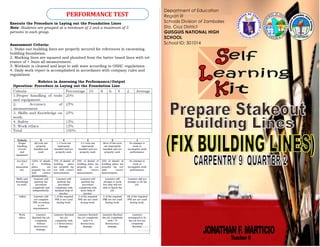
- 1. Department of Education Region III Schools Division of Zambales Sta. Cruz District GUISGUIS NATIONAL HIGH SCHOOL School ID: 301014 PERFORMANCE TEST Execute the Procedure in Laying out the Foundation Lines Note: Students are grouped at a minimum of 2 and a maximum of 5 persons in each group. Assessment Criteria: 1. Stake-out building lines are properly secured for references in excavating building foundation. 2. Marking lines are squared and plumbed from the batter board lines with tol- erance of + 3mm all measurement. 3. Worksite is cleaned and kept in safe state according to OSHC regulations. 4. Daily work report is accomplished in accordance with company rules and regulations
- 2. Again, Welcome to the Self-Learning Kit for “Carpentry NC II TLE Grade 9” This kit contains training materials and activities for you to complete for the 2nd Quarter. • Square building lines with end tolerance of +/-3mm. • Measure and set building lines. • Use PPE according to job requirements. A blueprint is a type of paper-based reproduction usually of technical drawing, documenting done by architecture or an engineering design. Gen- erally, the term "blueprint" refers to any detailed plan of a building. A working drawing is a type of technical drawing, which is part of the doc- umentation needed to build an engineering product or architectural plan. Building plans and Specifications form part of the working drawings needed in any construction project. A working drawing should include the following: 1. Site Plan essentially shows the location of a building or house site. It includes the following: site boundaries site is located ment About BLUEPRINT reading... Multiple choice: Choose the letter of the correct answer. SUMMATIVE TEST QUARTER 2 1. A type of drawing that shows the layout of a building taken at a level plan through windows and doors approximately 1 meter from the floor. a. Floor plan b. Site plan c. Elevation d. Details 2. It is a written document prepared by an architect which serves as a set of instructions or guidelines that accompanies a working drawing. a. Floor plan b. Site plan c. Specification d. Layout 3. This plan essentially shows the location of a building or house site. a. Floor plan b. Site plan c. Elevation d. Details 4. It is a cone-shaped metal suspended on a string used to check or obtain a vertical line. a. Steel square b. Plastic hose c. Level bar d. Plumb bob II.Identification: Identify what is being referred to in the follwing statements: 5. This pertains to lines representing the side of the building passing through the center of the foundation post. 6.It is a scaled drawing of the front, rear or side of a building. It includes dimensions that cannot be shown on a floor plan such as the height dimension. 7. It is the shorter and narrower part of the square. 8. A square with blade ranging from 6 inches to 12 inches. 9. It is one of the best and accurate tools for guiding work in establishing a horizontal level. 10. A type of paper-based reproduction usually of a technical drawing, documenting an architecture or an engineering design III.Fill in the blank: Fill in the blanks with a word or group of words to complete the sentence. Procedures in Laying out the Foundation Lines 11. __________ the oriented line to the top of the batter boards. This is done by hang- ing a plumb bob to the oriented line, and by making the corresponding point on the batter board. 12. __________ the center of the foundation from the orientation line at the opposite batter boards. Mark these two points with nails or a saw kerf. 13. Stretch string No. 1 on these two marks. Anchor it to the batter boards. This line should never be moved during the process of _____________lines. 14. Tie a cord to this line to indicate the original corner A. Align this cord to the ____________ with a plumb bob. 15. ______________ the length of the side that falls on line 1, starting from the origi- nal corner, and tie another cord to mark this corner B. 16. Sketch line No. 2 square or _______________ to line 1, passing through the cord tied at the original corner A. Tie line 2 to nails on the batter boards. 17. From the ________________ of lines 1 and 2 at the original corner A. Measure the length of the side of the building that falls on string 2.Tie another cord to mark this corner C. 18. Through this corner just mark, _____________ string 3 square to string 2. 19. Measure the ___________ of the side that falls on line 3, and tie a cord to mark corner D. 20. Through corner D, stretch line 4 to the ___________ corner B on line1. Check the squareness of these two lines. Through the four sides of the building are completely laid out there is a need to check squareness by the use of the diagonal.
- 3. 4. Tie a cord to this line to indicate the original corner A. Align this cord to the corner stake with a plumb bob. 5. Measure the length of the side that falls on line 1, start- ing from the original corner, and tie another cord to mark this corner B. 6. Sketch line No. 2 square or perpendicular to line 1, passing through the cord tied at the original corner A. Tie line 2 to nails on the batter boards. 7. From the intersection of lines 1 and 2 at the original corner A. Measure the length of the side of the building that falls on string 2. Tie another cord to mark this cor- ner C. 8. Through this corner just mark, stretch string 3 square to string 2. 9. Measure the length of the side that falls on line 3, and tie a cord to mark corner D. 10.Through corner D, stretch line 4 to the adjacent corner B on line 1. Check the squareness of these two lines. Note: Through the four sides of the building are com- pletely laid out there is a need to check squareness by the use of the Framing square or diagonal. 2. Floor Plan is a drawing showing the layout of a building taken at a level plan through windows and doors approximately one meter up from the floor. It shows the following: -in furniture cal order nal lines to represent hips and valleys. 3. Elevation is a scaled drawing of the front, rear or side of a building. It includes dimensions that cannot be shown on a floor plan such as the height dimen- sion. 4. Details Most working draw- ings are drawn to the scale of 1:100, which is rather small. It is not always possible to show im- portant shapes, positions for assembly, and dimensions of specific parts of a building. A separate drawing is made using the larger scales of 1:5 or 1:10. 43 5. Specification is a written doc- ument prepared by an architect which serves as a set of instruc- tion or guidelines that accompa- nies a working drawing. It describes how certain aspects of building construction are to be done and which materials are to be used. It also describes their desired quality and the expected standard of work. Knowing how to read and interpret a working drawing saves time, money and effort in the construction of the building. ASSESSMENT CRITERIA: 1. Stake-out building lines are properly secured for references in excavating building foundation. 2. Marking lines are squared and plumbed from the batter board lines with tolerance of + 3mm all measurement. 3. Worksite is cleaned and kept in safe state according to OSHC regulations. 4. Daily work report is accomplished in accordance with company rules and regulations.
- 4. Good carpentry work demands accuracy in measurement. This could be done only with the aid of various testing tools to accomplish a precise and quality work. It is important to know the various testing tools and how to use them properly. They may cause accidents if proper care and use are not observed. Using proper tools in the proper job can prolong their use. Types of Testing Tools and Their Uses 1. Square is a 90o standard right angle sometimes called try square used for testing squareness of work. Types of Squares: A. Try square is a square with blade ranging from 6 inches to 12 inches. B. Miter square is a square with blade permanently set at 45o. C. Combination try and miter square is a combination of 45o and 90o in one set. D. Combination square is similar in appearance to try square only that the head can be slide and clamped at any desired distance from the blade. It is also provided with a meter and level guide. E. Sliding T-bevel is like a try square with sliding and adjustable blade that could be set any angle. F. Framing or steel square is used effectively on various framing works. Parts of Framing Square: A. Body is the longer and wider part B. Tongue is the shorter and narrower part of the square C. Face is the side visible when the square is held by the tongue with the left hand and the body pointing to the right. D. Heel is the point at which the tongue and body meet on the outside edge. 3. Plastic hose with water is one of the best and accurate tools for guiding work in estab- lishing a horizontal level. 4. Plumb bob is a cone-shaped metal suspended on a string used to check or obtain a vertical line. Directions: Based on a given blueprint plan, answer the follow- ing questions 1) Explain the use of a working plan. 2) Enumerate the components of a blueprint plan. 3) What does the elevation plan show? 4) What particular dimension is found in an elevation plan? 5) What is the importance of a detailed drawing? 6) What is the vital aspect of specification? 7) What are the names of different rooms in the floor plan? 8) What is the area of bedroom no. 1, no. 2? 9) How long is the building? 10) How wide is the building? 11) What is the floor area of the building? TYPES, FUNCTIONS AND USES OF TESTING TOOLS BLUEPRINT READING Direction: Match column A with column B. Write your an- swers in your notebook. TYPES, FUNCTIONS AND USES OF TESTING TOOLS Building lines pertain to lines representing the side of the building passing through the center of the foundation posts. The final laying-out is done on the batter board. Before the builder can start the layout, he has to decide which among the building lines he is going to use. Procedure in Laying out the Foundation Lines: 1. Transfer the oriented line to the top of the batter boards. This is done by hanging a plumb bob to the oriented line, and by making the corresponding point on the batter board. 2. Locate the center of the foundation from the orientation line at the opposite batteboards. Then mark these two points with nails or a saw kerf. 3. Stretch string No. 1 on these two marks. Anchor it to the batter boards. This line should never be moved during the process of squaring lines.