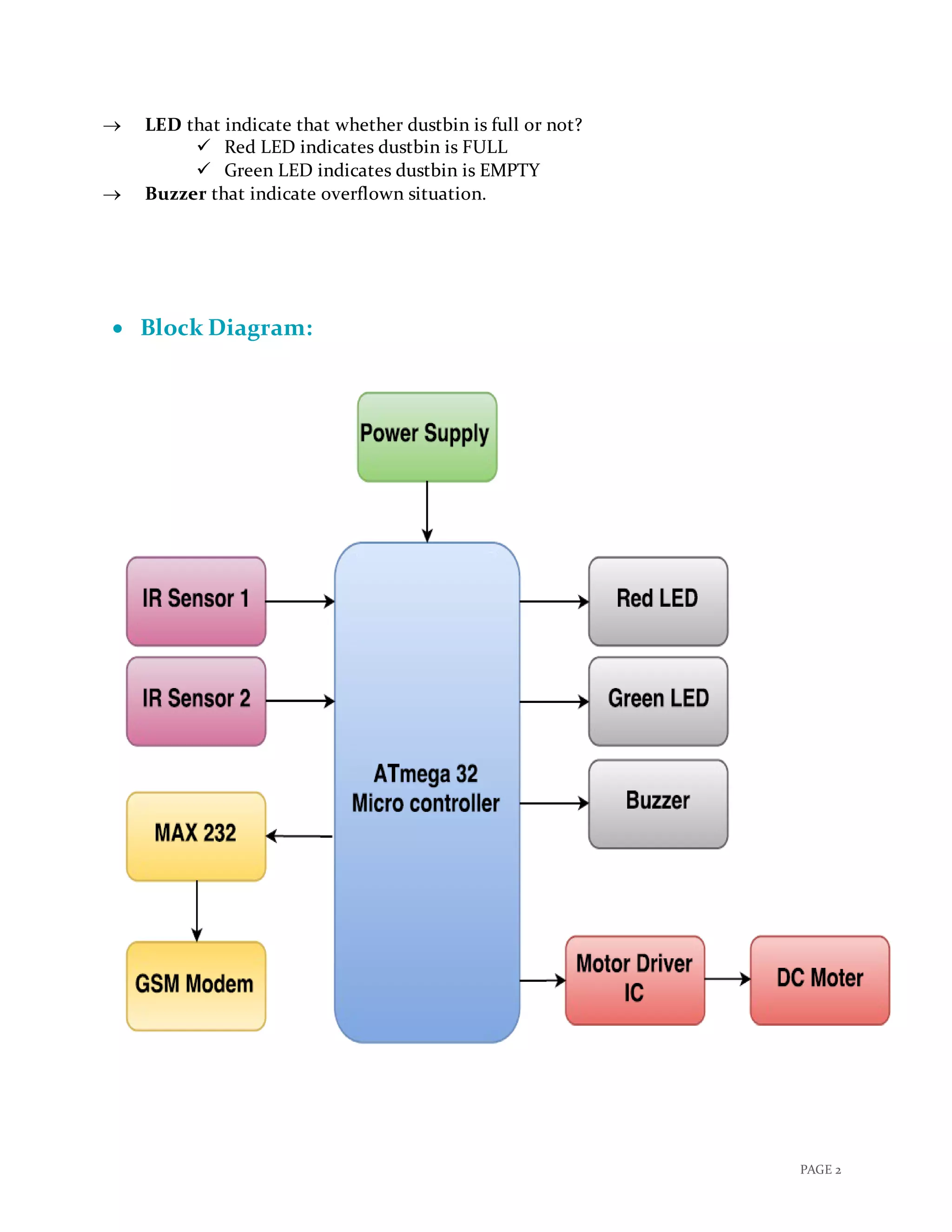
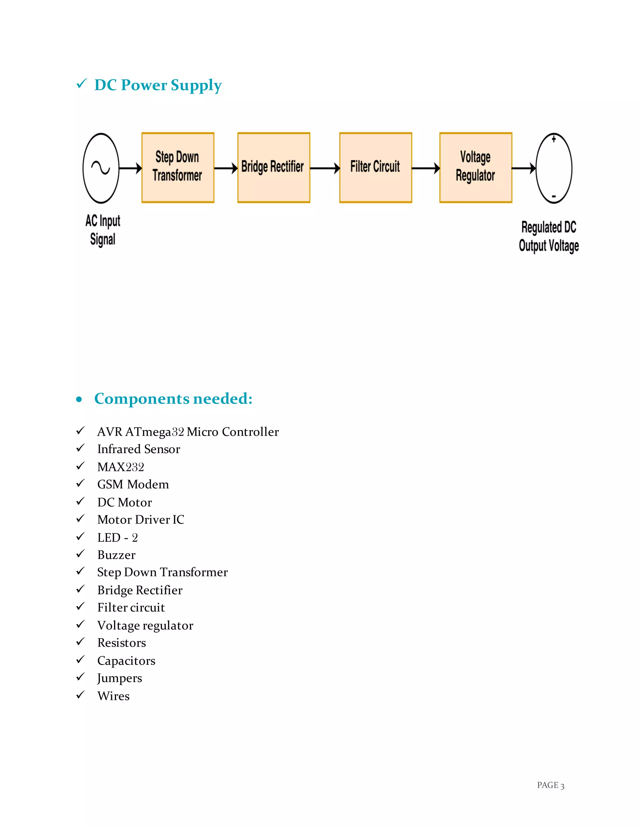
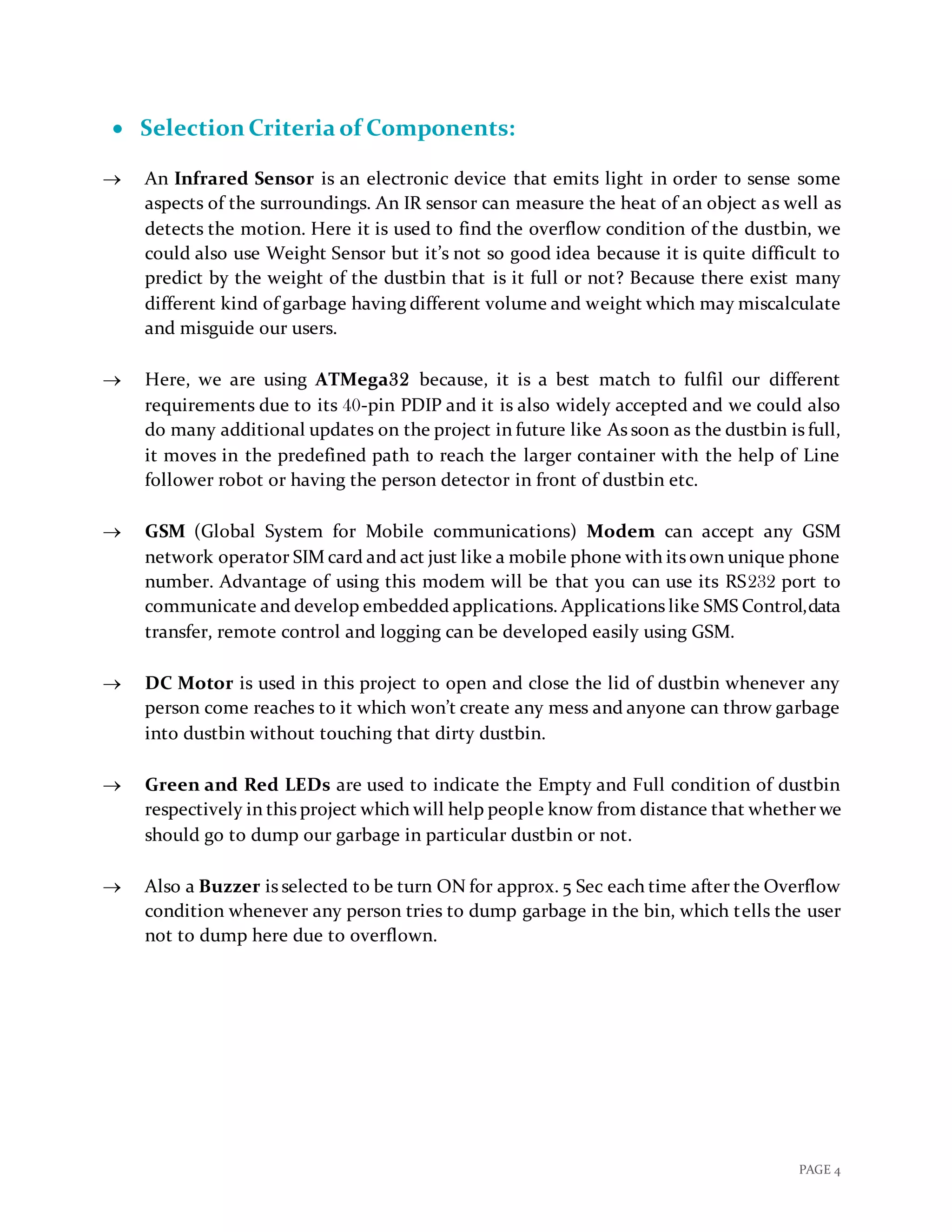
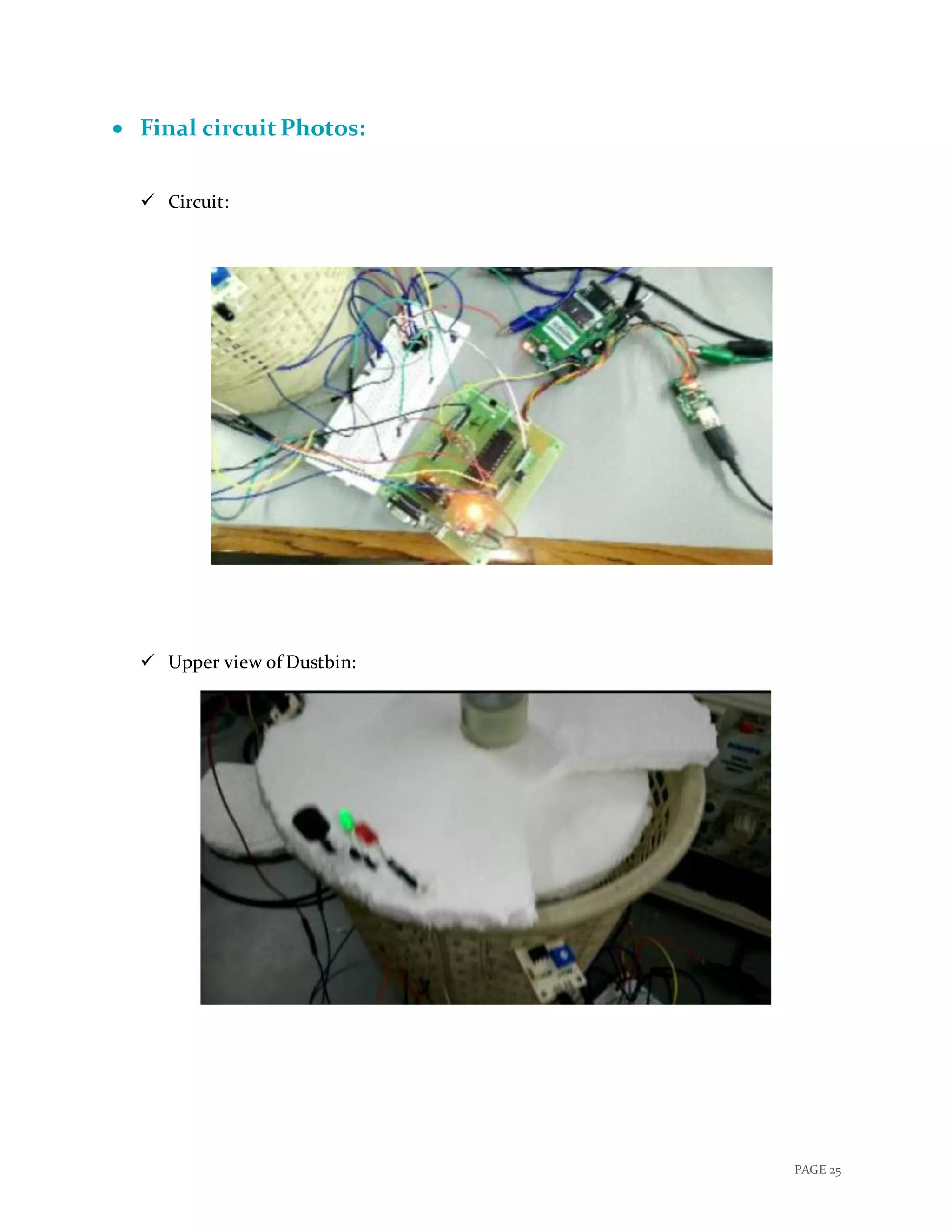
SlideShare a Scribd company logo
1 of 31
Download to read offline
“SMART DUSTBIN”
A PROJECT REPORT
Submitted by
GROUP: 41
CHARMI CHOKSHI (201501021)
DHRUTI CHANDARANA (201501015)
In fulfillment of the course
EMBEDDED SYSTEM DESIGN
In
INFORMATION AND COMMUNUCATION TECHNOLOGY
PAGE 1
 Motivation:
 With increase of population, the scenario of cleanliness with respect to garbage
management is degrading tremendously. In city there are many public places where we
see that garbage bins or dustbins are placed but are overflowing. This creates
unhygienic condition in the nearby surrounding. Also creates ugliness and some serious
diseases, at the same time bad smell is also spread and it also degrades the valuation of
that area.
 To avoid such situation we come up with a project called “Smart Dustbin” which is a
GSM based Garbage and waste collection bins overflow indicator system for Smart
Cities.
 Over main motivation behind this project is the ongoing campaign Swachh Bharat
Abhiyan (Clean India Movement) launched on October 02, 2014 at Rajghat, New Delhi,
by the Prime Minister of India Narendra Modi which is India's largest ever cleanliness
drive to clean the streets, roads and infrastructure of the country's 4,041 statutory cities
and towns.
 Description:
 As people are getting smarter so are the things. While the thought comes up for Smart
cities there is a requirement for Smart waste management. The idea of Smart Dustbin
is for the Smart buildings, Colleges, Hospitals and Bus stands.
 Smart dustbins is a new idea of implementation which makes a normal dustbin smart
using Infrared Sensors for garbage level detection and sending message to respective
municipal authorities updating the status of the bin using GSM modem.
 Even this is a touch free dustbin so, when any person reaches near to it, the lid of it will
open automatically so there is no need to open that dirty lid by your hands.
 This project also include a Green LED to indicate that the dustbin is Empty and a Red
LED to indicate the Full condition.
 As soon as the garbage inside the dustbin reaches as the approx. level of 90% a Buzzer
will turn ON for few seconds to tell the user not to use this dustbin and Red LED will
be turned on until it’s Empty again.
 Till the dustbin is empty again, the lid will not open so that no one can through garbage
into it and create mess.
 Final Outcome:
 This project will send an SMS to respective municipal authorities which contains the
details about the overflown dustbin.
 Lid of dustbin will be opened when any person reaches near to it.
PAGE 2
 LED that indicate that whether dustbin is full or not?
 Red LED indicates dustbin is FULL
 Green LED indicates dustbin is EMPTY
 Buzzer that indicate overflown situation.
 Block Diagram:
PAGE 3
 DC Power Supply
 Components needed:
 AVR ATmega32 Micro Controller
 Infrared Sensor
 MAX232
 GSM Modem
 DC Motor
 Motor Driver IC
 LED - 2
 Buzzer
 Step Down Transformer
 Bridge Rectifier
 Filter circuit
 Voltage regulator
 Resistors
 Capacitors
 Jumpers
 Wires
PAGE 4
 Selection Criteria of Components:
 An Infrared Sensor is an electronic device that emits light in order to sense some
aspects of the surroundings. An IR sensor can measure the heat of an object as well as
detects the motion. Here it is used to find the overflow condition of the dustbin, we
could also use Weight Sensor but it’s not so good idea because it is quite difficult to
predict by the weight of the dustbin that is it full or not? Because there exist many
different kind of garbage having different volume and weight which may miscalculate
and misguide our users.
 Here, we are using ATMega32 because, it is a best match to fulfil our different
requirements due to its 40-pin PDIP and it is also widely accepted and we could also
do many additional updates on the project in future like As soon as the dustbin is full,
it moves in the predefined path to reach the larger container with the help of Line
follower robot or having the person detector in front of dustbin etc.
 GSM (Global System for Mobile communications) Modem can accept any GSM
network operator SIM card and act just like a mobile phone with its own unique phone
number. Advantage of using this modem will be that you can use its RS232 port to
communicate and develop embedded applications. Applications like SMS Control,data
transfer, remote control and logging can be developed easily using GSM.
 DC Motor is used in this project to open and close the lid of dustbin whenever any
person come reaches to it which won’t create any mess and anyone can throw garbage
into dustbin without touching that dirty dustbin.
 Green and Red LEDs are used to indicate the Empty and Full condition of dustbin
respectively in this project which will help people know from distance that whether we
should go to dump our garbage in particular dustbin or not.
 Also a Buzzer is selected to be turn ON for approx. 5 Sec each time after the Overflow
condition whenever any person tries to dump garbage in the bin, which tells the user
not to dump here due to overflown.
PAGE 5
 Circuit Diagram:
 Click here to view clear Circuit Diagram!
-
Atmega32
O
+
-
SIM300
Buzzer
TXD
Green LED
IR
Sensor
IR
Sensor
PB0/(XCK/T0)
1
PB1/(T1)
2
PB2/(INT2/AIN0)
3
PB3/(OC0/AIN1)
4
PB4/(SS)
5
PB5/(MOSI)
6
PB6/(MISO)
7
PB7/(SCK)
8
RESET
9
XTAL2
12
XTAL1
13
PD0/(RXD)
14
PD1/(TXD)
15
PD2/(INT0)
16
PD3/(INT1)
17
PD4/(OC1B)
18
PD5/(OC1A)
19
PD6/(ICP)
20
PD7/(OC2)
21
VCC
10GND
11
GND
31
PA7/(ADC7)
33PA6/(ADC6)
34PA5/(ADC5)
35PA4/(ADC4)
36
PA2/(ADC2)
37
PA3/(ADC3)
38
PA1/(ADC1)
39PA0/(ADC0)
40
PC0/(SCL)
22PC1/(SDA)
23PC2/(TCK)
24PC3/(TMS)
25PC4/(TDO)
26PC5/(TDI)
27PC6/(TOSC1)
28PC7/(TOSC2)
29
AVCC
30
AREF
32
Microcontroller Connection Circuit Diagram
R2
R3
+
DC
Motor
GSM Module
R1
VCC1VCC2
1
2
3
4
EN1
EN2
GND
GND
GND
GROUND
IN1
IN2
IN3
IN4
OUT1
OUT2
OUT3
OUT4
Heat Sink
U1
L293D
1
10
15
9
14
11
6
32
7
16
13
125
4
8
O
RXD
Red LED
7-12 V
GND
PAGE 6
 Power Supply Design Circuit:
+12 V DC
U29
LM7812
VIN
1
GND
3
VOUT
2
V+
Power Supply Design Circuit
1N4007
1 uF
Down
230 V
_
V-
25 V
1000 uF
Step
+
1 5
4 8
Transformer
AC Supply
- +
PAGE 7
 Flow Chart:
PAGE 8
 Datasheet of Major Components:
 AVR ATmega32 MicroController:
 High-performance, Low-power
 8-bit Microcontroller
 Architecture: Advanced RISC
 32 × 8 General Purpose Working Registers
 131 Powerful Instructions – Most Single-clock Cycle Execution
 32KB flash memory, 1KB EEROM , 2KB SRAM
 32 Programmable I/O Lines
 40-pin PDIP
 Operating Voltage: 4.5V - 5.5V
 Two 8-bit Timer/Counters with Separate Prescalers and Compare Modes
 One 16-bit Timer/Counter with Separate Prescaler, Compare Mode, and
Capture Mode
PAGE 9
 Infrared Sensor:
 Very low supply current
 Supply voltage: 2.5 V to 5.5 V
 Photo detector and preamplifier in one package
 Internal filter for PCM frequency
 Insensitive to supply voltage ripple and noise
 PIN 1: OUT
 PIN 2: GND
 PIN 3: Vs
 Improved immunity against ambient light
 Detection: Indicated by active high Output
PAGE 10
 MAX232:
 Meets or Exceeds TIA/EIA-232-F and ITU Recommendation V.28
 Operates From a Single 5-V Power Supply With 1.0-μF Charge-Pump
Capacitors
 Operates up to 120 kbit/s
 Two Drivers and Two Receivers
 ±30-V Input Levels
 Low Supply Current: 8 mA Typical
 ESD Protection Exceeds JESD 22 − 2000-V Human-Body Model (A114-A)
 Upgrade With Improved ESD (15-kV HBM) and 0.1-F Charge-Pump
Capacitors is Available With the MAX202
PAGE 11
 GSM Modem:
 Dual-Band GSM/GPRS 900/ 1800 MHz
 RS232 interface for direct communication with computer or MCU kit
 Configurable baud rate
 Power controlled using 29302WU IC
 ESD Compliance
 Enable with MIC and Speaker socket
 With slid in SIM card tray
 With Stub antenna and SMA connector
 Input Voltage: 12V DC
PAGE 12
 DC Motor:
 DC Supply: 4 – 12 V
 RPM: 30 at 12 V
 No Load current: 50 mA at 12 V
 Load current: 300 mA(max) at 12 V
 Torque: 5 Kg-cm at 12 V
 Total length: 46 mm
 Motor diameter: 36 mm
 Brush type: precious metal
 Output shaft: centred
 Shaft diameter: 6 mm
 Motor weight: 100 gm
PAGE 13
 Connecting GSM Modem with AVR microcontroller:
GSM Modem RS232 is built with Dual Band GSM engine- SIM900A.
GSM modem (GSM Sim 900A) is used to make audio calls, SMS and DATA transfer
application in M2M is a machine to machine interface that enables networked
devices to exchange information. With the use of MAX232 chip we are able to
connect GSM modem with microcontroller.
It can be used in Access Control Devices, Supply Chain Management and Security
System.
 Details of GSM Modem:
 Working Frequency: 900 MHz to 1800 MHz
 Baud Rate: 9600 to 115200
 Internal TCP/IP stack to connect internet via GPRS
 SIM card holder
 Built in network status LED.
 Working Principle:
GSM modem doesn’t have a keypad and display to interact with; it accepts AT
commands through a serial interface. Every Commands starts with AT that’s why
they are called AT commands; here AT stands for attention.
Connecting GSM modem with microcontroller with use of MAX232 IC:
1. Connect T1IN (transmit pin of MAX232) to the transmitter pin of
microcontroller and R1out (receive pin of MAX232) to the receiver pin of
microcontroller.
2. Connect T1out pin of MAX232 to the transmitter pin of GSM modem and R1IN
pin of MAX232 to receiver pin of GSM modem.
Following steps are used to send text message to a mobile phone through GSM
modem:
1. Select GSM modem in text mode.
2. Send mobile number of the recipient to the GSM modem.
3. Send text message string to GSM modem.
4. Send ASCII code of CTRL + Z (0x1A) to GSM modem to transmit the message
to mobile phone.
PAGE 14
 Circuit Diagram:
 Code to connect GSM Modem with Microcontroller:
#include<string.h>
void usart_initialize()
{
UCSRB=0x08; //Tx Enable
UCSRC=0x86; // Data Size : 8-bit, Stop Bit:1,No parity
UBRRL=0x33; // X= (Fosc/(16(Desired Baud Rate)))-1
// =(8*10^6/(16 *9600))-1
// =52.08-1
// =51 (Dec)
//Here, URSEl=0, so Fosc is divided by 16 if it was 1 //Fosc would Have
been divided by 8
}
//USART Send
void usart_send(unsigned char ch)
{
while(UCSRA.B5==0); // Wait till UDR is empty
UDR=ch; //Write the value to be Tx
}
void main()
{
PAGE 15
unsigned char str[] =
"ATrnAT+CSMINS?rnAT+CREG?rnATE1rnAT+CMGF=1rnAT+CSCS="GSM"
rnAT+CSMP=17,167,0,16rnAT+CMGS="+91**********"rHi I am sim300n";
int str_len=strlen(str);
int i=0;
usart_initialize();
while(1)
{
usart_send(str[i++]); //Send data
if (i>=str_len) // Till string Length
{
i=0;
usart_send(26);
delay_ms(2000);
break;
}
delay_ms(300);
}
}
PAGE 16
 Connecting IR Sensor with AVR microcontroller:
IR sensor is an electronic device that emits in order to sense some aspects of the
surrounding. It can measure the heat as well as the motion of the object; these types of
sensor will not emit an infrared radiation but it will detect an infrared radiation. Generally
all objects radiate some of infrared radiation which is not visible to our eyes but it can be
detected by IR sensor.
It can be used to detect any object or moment of the object. IR sensor with higher
capabilities are used in Night Vision Devices, Infrared Astronomy and Infrared Tracking
etc.
 Details of IR sensor:
 Nominal Frequency: 1𝑀𝐻𝑧
 Supply Voltage: 3.3𝑉 ±10%
 Input Current: Max 35𝑚𝐴
 Operating Temperature: -40˚c to 85˚c
 Start Up Time: Max 10𝑚𝑆
 Working Principle:
When there is an object near IR sensor the output of sensor will be high and when
there is no object output is low.
1. Connect the output of IR sensor to the pin of the microcontroller; this pin will be
input pin for the microcontroller.
2. If Input pin is 1 then LED will blink else it will not.
 Circuit Diagram:
PAGE 17
 Code to connect IR sensor with microcontroller:
#include <avr/io.h>
int main(void){
DDRA= 0x00; //Input Port to take output of IR sensor
DDRB= 0x01; //Port to control LED
while (1)
{
if(PINA == 1)
{ //Output of sensor is high: there is an object
PORTB= 0x01; //LED will turn ON
}
Else
{ //Output of sensor is low: there is no object
PORTB= 0x00; //LED will turn OFF
}
}
}
PAGE 18
 Connecting DC Motor with AVR microcontroller:
DC-motor is a rotary electrical machine that converts direct current electrical
energy into mechanical energy. All types of DC-motor have same internal mechanism,
either electromagnetic or electronic. Speed of DC-motor can be controlled by a variable
supply voltage of by changing current in its field.
It can be used in some tools and toys, fan, blower, conveyor, lift and spinning machine
etc.
 Details of DC-motor:
 RPM: 30
 Voltage: 4-12V (Max: 36V)
 Current: 45mA
 Gear Ratio: 100:1
 Working Principle:
Working principle of DC-motor is that when a current carrying conductor placed
in magnetic field, it experiences a mechanical force. Direction of this mechanical force is
given by Fleming’s left-hand rule.
 Following are the steps to connect DC-motor with microcontroller:
(Here, we are using L239D motor driver IC to drive motor)
1. Connect Pin: 1 &16 of IC to Vcc and Pin: 3, 4 & 12,13 to Gnd of the microcontroller.
2. Connect Pin: 2 & 6 of IC to any Port pin of microcontroller these pins of IC are
inputs of IC, these inputs are used to drive the motor. Details to drive motor using
these inputs is shown in below table:
Input: 1 Input: 2 Motor Rotation
0 0 Stop
0 1 Anti- clock wise
1 0 Clock wise
1 1 Stop
3. Connect Pin: 3 & 5 of IC to DC- motor.
4. Provide input value from microcontroller to operate motor in a particular
direction or to stop motor.
PAGE 19
 Circuit Diagram:
 Code to connect DC-motor with microcontroller:
#include <avr/io.h>
#include <util/delay.h>
int main(void)
{
DDRA= 0xFF;
//Output Port that will control inputs of L239D IC: control rotation of motor
while (1)
{ //Infinite Loop
PORTA= 0x01; //Motor will rotate anti-clock wise
_delay_ms(1000); //delay of 1 second
PORTA= 0x02; //Motor will rotate clock-wise
_delay_ms(1000); //delay of 1 second
PAGE 20
PORTA= 0x00; //Motor stops;
_delay_ms(1000); //delay of 1 second
}
return 0;
}
PAGE 21
 Connecting Buzzer with AVR microcontroller:
Buzzer is an electronic device that converts the electronic signals into
buzzing noise; which may be mechanical, electromechanical or piezoelectric.
It can be used in alarm devices, timers, electronic bell and confirmation of user input
such as mouse click or keystroke.
 Details about Buzzer:
 We are using piezoelectric buzzer.
 Maximum Input Voltage: 30 𝑉
 Sound Pressure: 70 𝑑𝐵𝐴/10𝑐𝑚
 Operating temperature: −10˚𝑐 𝑡𝑜 70˚𝑐
 Working Principle:
Piezoelectric buzzer use the inverse piezoelectric principle to create
movement of a ceramic disc to produce sound waves.
Following are the steps to connect buzzer with microcontroller:
1. Connect Buzzer with a PORT pin of microcontroller.
2. Provide Logic 1 to turn on the buzzer and Logic 0 to turn off the buzzer.
 Circuit Diagram:
PAGE 22
 Code to connect Buzzer with Microcontroller:
#include <avr/io.h>
#include <util/delay.h>
int main (void)
{
//Initializing Port
//Connecting Buzzer with PORTA
DDRA = 0x01; //PIN0 of PORTA initialize as output
PORTA = 0x00; //Initial value
/*Infinite Loop */
while(1)
{
//Toggling the value of port after every second
PORTA= 0x01; //Buzzer will turn ON
_delay_ms(1000); //Delay of 1 second
PORTA= 0x00; //Buzzer will turn OFF
_delay_ms(1000); //Delay of 1 second
}
}
PAGE 23
 Connecting LED with AVR microcontroller:
A Light-Emitting Diode is a two-lead semiconductor light source. It is a P-N
junction diode, which emits light when activated. It has many advantages lower
energy consumption, smaller size, longer lifetime etc.
It can be used in remote control device, home application and in automobile
application. It can be also used as indicator, flashlight etc.
 Details of LED:
 Supply Current: 16 − 18 𝑚𝐴 (Max:20𝑚𝐴)
 Voltage: 5𝑉
 Power Dissipation: 105 𝑚𝑊
 Operating Temperature: −40˚𝑐 to 85˚𝑐
 Working Principle:
When a suitable voltage is applied to the LED, electrons are able to
recombine with electron holes within the device, releasing the energy in the form of
photons. This effect is called “electroluminescence” and the color of the light is
determined by the energy gap of the semiconductor.
Following are the steps to connect LED with microcontroller:
1. Connect LED with a PORT pin of microcontroller; use resistor to control
current.
2. Provide Logic 1 to pin to turn on the LED and Logic 0 to turn off the LED.
 Circuit Diagram:
PAGE 24
 Code to connect LED with microcontroller:
#include <avr/io.h>
#include <util/delay.h>
int main (void)
{
//Initializing Port
//Connecting LED with PORTA
DDRA = 0x01; //PIN0 of PORTA initializeas output
PORTA = 0x00; //Initial value
/*Infinite Loop */
while(1)
{
//Toggling the value of port after every second
PORTA= 0x01; //LED will turn ON
_delay_ms(1000); //Delay of 1 second
PORTA= 0x00; //LED will turn OFF
_delay_ms(1000); //Delay of 1 second
}
}
PAGE 25
 Final circuit Photos:
 Circuit:
 Upper view of Dustbin:
PAGE 26
 Connected sensor with dustbin:
 Getting final SMS in mobile phone:
 Video:
 Click here to play the Video!
PAGE 27
 Final Code:
#include<string.h>
void usart_initialize()
{
UCSRB=0x08; //Tx Enable
UCSRC=0x86; // Data Size : 8-bit, Stop Bit:1,No parity
UBRRL=0x33; // X= (Fosc/(16(Desired Baud Rate)))-1
// =(8*10^6/(16 *9600))-1
// =52.08-1
// =51 (Dec)
//Here, URSEl=0, so Fosc is divided by 16 if it was 1 //Fosc would
Have been divided by 8
}
//USART Send
void usart_send(unsigned char ch)
{
while(UCSRA.B5==0); // Wait till UDR is empty
UDR=ch; //Write the value to be Tx
}
void send_SMS(unsigned char str[], int str_len)
{
int i=0;
int cnt = 1;
while(cnt != 5)
{
usart_send(str[i++]); //Send data
if (i>=str_len) // Till string Length
{
i=0;
usart_send(26);
delay_ms(2000);
cnt = 5;
//break;
}
delay_ms(300);
}
}
void main() {
PAGE 28
int j=1;
int k=0;
unsigned char
str[]="ATrnAT+CSMINS?rnAT+CREG?rnATE1rnAT+CMGF=1rnAT+CSCS="
GSM"rnAT+CSMP=17,167,0,16rnAT+CMGS="+91**********"rALERT!nDustbin:
001 is filled...n";
int str_len=strlen(str);
unsigned char
str1[]="ATrnAT+CSMINS?rnAT+CREG?rnATE1rnAT+CMGF=1rnAT+CSCS="
GSM"rnAT+CSMP=17,167,0,16rnAT+CMGS="+91**********"rGarbage collected
from Dustbin 001.n";
int str_len1=strlen(str1);
DDRB = 0x00;
DDRC = 0x03;
DDRA= 0x03;
DDRD= 0x00;
while(1)
{
if(PINB.B0 == 1)
{
PORTC.B1 = 1; //red led ON
PORTC.B2 = 0; //green led off
if(j == 1)
{
PORTC.B0 = 1; //buzzer ON
Delay_ms(4000);
PORTC.B0 = 0x00; ///buzzer off
usart_initialize();
send_SMS(str, str_len);
j=0;
k=1;
}
PORTC.B0 = 0x00; ///buzzer off
}
else if(PINB.B0 == 0)
{
PORTC.B0 = 0; //buzzer off
PORTC.B1 = 0; //red led off
PAGE 29
PORTC.B2 = 1; //green ON
j=1;
if(k == 1)
{
usart_initialize();
send_SMS(str1, str_len1);
k=0;
PORTC.B2=0;
delay_ms(1000);
PORTC.B2= 1;
}
}
if(PINB.B1 == 1){
PORTA= 0x02;
delay_ms(1300);
PORTA= 0x00;
delay_ms(1300);
PORTA= 0x01;
delay_ms(1300);
PORTA= 0x00;
}
else{
PORTA= 0x00;
}
}
}
PAGE 30
 Time Line of Project:
Date 06-03-17 20-03-17 27-04-17 10-04-17 17-04-17
Work Done
Project Formation 
Collection of Components 
Code Programing 
Build Circuit 
Debugging whole System 

More Related Content

What's hot

Smart Bins : IOT Based Garbage Monitoring System
Smart Bins : IOT Based Garbage Monitoring SystemSmart Bins : IOT Based Garbage Monitoring System
Smart Bins : IOT Based Garbage Monitoring SystemKavish Khullar
 
Smart dustbin for smart city
Smart dustbin for smart citySmart dustbin for smart city
Smart dustbin for smart citySanjib Mitra
 
IoT Based Garbage Monitoring System ppt
IoT Based Garbage Monitoring System pptIoT Based Garbage Monitoring System ppt
IoT Based Garbage Monitoring System pptRanjan Gupta
 
RFID based smart shopping cart and billing system
RFID based smart shopping cart and billing systemRFID based smart shopping cart and billing system
RFID based smart shopping cart and billing systemlaharipothula
 
IoT based garbage monitoring system
IoT based garbage monitoring systemIoT based garbage monitoring system
IoT based garbage monitoring systemRanjan Gupta
 
[Year 2015-16 ] IOT Based Waste Management
[Year 2015-16 ]  IOT Based Waste Management[Year 2015-16 ]  IOT Based Waste Management
[Year 2015-16 ] IOT Based Waste ManagementSaurabh N. Mehta
 
Project report on Iot Based Garbage Monitoring System
Project report on Iot Based Garbage Monitoring System  Project report on Iot Based Garbage Monitoring System
Project report on Iot Based Garbage Monitoring System alok pal
 
Garbage Monitoring System using Arduino
Garbage Monitoring System using ArduinoGarbage Monitoring System using Arduino
Garbage Monitoring System using Arduinoijtsrd
 
Application of IOT "Smart Bin"
Application of IOT "Smart Bin"Application of IOT "Smart Bin"
Application of IOT "Smart Bin"Akhil Goyal
 
Smart Intelligent trolley
Smart Intelligent trolley Smart Intelligent trolley
Smart Intelligent trolley yokesh waran
 
Intelligent shopping cart
Intelligent shopping cartIntelligent shopping cart
Intelligent shopping cartAshutha K
 
Iot based garbage monitoring system
Iot based garbage monitoring systemIot based garbage monitoring system
Iot based garbage monitoring systemankitguptakishu
 
Distance Measurement by Ultrasonic Sensor
Distance Measurement by Ultrasonic SensorDistance Measurement by Ultrasonic Sensor
Distance Measurement by Ultrasonic SensorEdgefxkits & Solutions
 
Blind Navigation system
 Blind Navigation system Blind Navigation system
Blind Navigation systemNilesh Jha
 
Final report obstacle avoiding roboat
Final report obstacle avoiding roboatFinal report obstacle avoiding roboat
Final report obstacle avoiding roboatShubham Thakur
 
Smart waste management system
Smart waste management systemSmart waste management system
Smart waste management systemShubham Thakur
 
Garbage monitoring system IOT
Garbage monitoring system IOTGarbage monitoring system IOT
Garbage monitoring system IOTamandeep singh
 

What's hot (20)

Smart Bins : IOT Based Garbage Monitoring System
Smart Bins : IOT Based Garbage Monitoring SystemSmart Bins : IOT Based Garbage Monitoring System
Smart Bins : IOT Based Garbage Monitoring System
 
Smart dustbin for smart city
Smart dustbin for smart citySmart dustbin for smart city
Smart dustbin for smart city
 
IoT Based Garbage Monitoring System ppt
IoT Based Garbage Monitoring System pptIoT Based Garbage Monitoring System ppt
IoT Based Garbage Monitoring System ppt
 
Smart bin
Smart binSmart bin
Smart bin
 
RFID based smart shopping cart and billing system
RFID based smart shopping cart and billing systemRFID based smart shopping cart and billing system
RFID based smart shopping cart and billing system
 
IoT based garbage monitoring system
IoT based garbage monitoring systemIoT based garbage monitoring system
IoT based garbage monitoring system
 
[Year 2015-16 ] IOT Based Waste Management
[Year 2015-16 ]  IOT Based Waste Management[Year 2015-16 ]  IOT Based Waste Management
[Year 2015-16 ] IOT Based Waste Management
 
Project report on Iot Based Garbage Monitoring System
Project report on Iot Based Garbage Monitoring System  Project report on Iot Based Garbage Monitoring System
Project report on Iot Based Garbage Monitoring System
 
Garbage Monitoring System using Arduino
Garbage Monitoring System using ArduinoGarbage Monitoring System using Arduino
Garbage Monitoring System using Arduino
 
Application of IOT "Smart Bin"
Application of IOT "Smart Bin"Application of IOT "Smart Bin"
Application of IOT "Smart Bin"
 
Smart Intelligent trolley
Smart Intelligent trolley Smart Intelligent trolley
Smart Intelligent trolley
 
Intelligent shopping cart
Intelligent shopping cartIntelligent shopping cart
Intelligent shopping cart
 
Iot based garbage monitoring system
Iot based garbage monitoring systemIot based garbage monitoring system
Iot based garbage monitoring system
 
Arduino Based Parking Lot System
Arduino Based Parking Lot SystemArduino Based Parking Lot System
Arduino Based Parking Lot System
 
Distance Measurement by Ultrasonic Sensor
Distance Measurement by Ultrasonic SensorDistance Measurement by Ultrasonic Sensor
Distance Measurement by Ultrasonic Sensor
 
Blind Navigation system
 Blind Navigation system Blind Navigation system
Blind Navigation system
 
Final report obstacle avoiding roboat
Final report obstacle avoiding roboatFinal report obstacle avoiding roboat
Final report obstacle avoiding roboat
 
Smart shopping trolley.
Smart shopping trolley.Smart shopping trolley.
Smart shopping trolley.
 
Smart waste management system
Smart waste management systemSmart waste management system
Smart waste management system
 
Garbage monitoring system IOT
Garbage monitoring system IOTGarbage monitoring system IOT
Garbage monitoring system IOT
 

Similar to Report smart dustbin

"Automatic Intelligent Plant Irrigation System using Arduino and GSM board"
"Automatic Intelligent Plant Irrigation System using Arduino and GSM board""Automatic Intelligent Plant Irrigation System using Arduino and GSM board"
"Automatic Intelligent Plant Irrigation System using Arduino and GSM board"Disha Modi
 
"Automatic Intelligent Plant Irrigation System using GSM and ARDUINO BOARD."
"Automatic Intelligent Plant Irrigation System using GSM and ARDUINO BOARD.""Automatic Intelligent Plant Irrigation System using GSM and ARDUINO BOARD."
"Automatic Intelligent Plant Irrigation System using GSM and ARDUINO BOARD."Disha Modi
 
Floor cleaning robot(autonomus mannual) vatsal shah-ec_4th year
Floor cleaning robot(autonomus mannual)  vatsal shah-ec_4th yearFloor cleaning robot(autonomus mannual)  vatsal shah-ec_4th year
Floor cleaning robot(autonomus mannual) vatsal shah-ec_4th yearVatsal N Shah
 
ACCIDENT PREVENTION AND SECURITY SYSTEM FOR AUTOMOBILES
ACCIDENT PREVENTION AND SECURITY SYSTEM FOR AUTOMOBILESACCIDENT PREVENTION AND SECURITY SYSTEM FOR AUTOMOBILES
ACCIDENT PREVENTION AND SECURITY SYSTEM FOR AUTOMOBILESAdrija Chowdhury
 
automatic plant irrigation using aurdino and gsm technology
automatic plant irrigation using aurdino and gsm technologyautomatic plant irrigation using aurdino and gsm technology
automatic plant irrigation using aurdino and gsm technologythamil arasan
 
IRJET- Low-Cost DTMF Controlled Landmine Detection Rover
IRJET- Low-Cost DTMF Controlled Landmine Detection RoverIRJET- Low-Cost DTMF Controlled Landmine Detection Rover
IRJET- Low-Cost DTMF Controlled Landmine Detection RoverIRJET Journal
 
Intelligent Farmer Friendly System
Intelligent Farmer Friendly SystemIntelligent Farmer Friendly System
Intelligent Farmer Friendly SystemIJMTST Journal
 
Vikaspptonnoticeboard
VikaspptonnoticeboardVikaspptonnoticeboard
VikaspptonnoticeboardVikas Singh
 
IRJET- Smart City to Phiysical Things
IRJET- Smart City to Phiysical ThingsIRJET- Smart City to Phiysical Things
IRJET- Smart City to Phiysical ThingsIRJET Journal
 
enoticeboard-150526024918-lva1-app6892 (2).pdf
enoticeboard-150526024918-lva1-app6892 (2).pdfenoticeboard-150526024918-lva1-app6892 (2).pdf
enoticeboard-150526024918-lva1-app6892 (2).pdfSupriaNandan
 
wireless E notice board
wireless E notice boardwireless E notice board
wireless E notice boardGanesh Gani
 
gsm based Notice board
gsm based Notice boardgsm based Notice board
gsm based Notice boardASHIRVAD KUMAR
 
Ultrasonic level meter
Ultrasonic level meterUltrasonic level meter
Ultrasonic level meterhandson28
 
WOMEN SAFETY DEVICE USING NFC
WOMEN SAFETY DEVICE USING NFC WOMEN SAFETY DEVICE USING NFC
WOMEN SAFETY DEVICE USING NFC venkteshb
 
Fingerprint Based Security System using GSM Module
Fingerprint Based Security System using GSM ModuleFingerprint Based Security System using GSM Module
Fingerprint Based Security System using GSM ModuleIJERA Editor
 
GSM BASED GAS ESCAPE BURST AND FIRE SAFETY PROJECT
GSM BASED GAS ESCAPE BURST AND FIRE SAFETY PROJECTGSM BASED GAS ESCAPE BURST AND FIRE SAFETY PROJECT
GSM BASED GAS ESCAPE BURST AND FIRE SAFETY PROJECTThrinadh Komatipalli
 
Automatic Crop Monitoring using Embedded System
Automatic Crop Monitoring using Embedded SystemAutomatic Crop Monitoring using Embedded System
Automatic Crop Monitoring using Embedded SystemIRJET Journal
 
[Year 2105-16]Pollution Monitoring using Cooperative Wireless Communication f...
[Year 2105-16]Pollution Monitoring using Cooperative Wireless Communication f...[Year 2105-16]Pollution Monitoring using Cooperative Wireless Communication f...
[Year 2105-16]Pollution Monitoring using Cooperative Wireless Communication f...Saurabh N. Mehta
 

Similar to Report smart dustbin (20)

"Automatic Intelligent Plant Irrigation System using Arduino and GSM board"
"Automatic Intelligent Plant Irrigation System using Arduino and GSM board""Automatic Intelligent Plant Irrigation System using Arduino and GSM board"
"Automatic Intelligent Plant Irrigation System using Arduino and GSM board"
 
"Automatic Intelligent Plant Irrigation System using GSM and ARDUINO BOARD."
"Automatic Intelligent Plant Irrigation System using GSM and ARDUINO BOARD.""Automatic Intelligent Plant Irrigation System using GSM and ARDUINO BOARD."
"Automatic Intelligent Plant Irrigation System using GSM and ARDUINO BOARD."
 
Floor cleaning robot(autonomus mannual) vatsal shah-ec_4th year
Floor cleaning robot(autonomus mannual)  vatsal shah-ec_4th yearFloor cleaning robot(autonomus mannual)  vatsal shah-ec_4th year
Floor cleaning robot(autonomus mannual) vatsal shah-ec_4th year
 
ACCIDENT PREVENTION AND SECURITY SYSTEM FOR AUTOMOBILES
ACCIDENT PREVENTION AND SECURITY SYSTEM FOR AUTOMOBILESACCIDENT PREVENTION AND SECURITY SYSTEM FOR AUTOMOBILES
ACCIDENT PREVENTION AND SECURITY SYSTEM FOR AUTOMOBILES
 
automatic plant irrigation using aurdino and gsm technology
automatic plant irrigation using aurdino and gsm technologyautomatic plant irrigation using aurdino and gsm technology
automatic plant irrigation using aurdino and gsm technology
 
IRJET- Low-Cost DTMF Controlled Landmine Detection Rover
IRJET- Low-Cost DTMF Controlled Landmine Detection RoverIRJET- Low-Cost DTMF Controlled Landmine Detection Rover
IRJET- Low-Cost DTMF Controlled Landmine Detection Rover
 
Intelligent Farmer Friendly System
Intelligent Farmer Friendly SystemIntelligent Farmer Friendly System
Intelligent Farmer Friendly System
 
Vikaspptonnoticeboard
VikaspptonnoticeboardVikaspptonnoticeboard
Vikaspptonnoticeboard
 
IRJET- Smart City to Phiysical Things
IRJET- Smart City to Phiysical ThingsIRJET- Smart City to Phiysical Things
IRJET- Smart City to Phiysical Things
 
enoticeboard-150526024918-lva1-app6892 (2).pdf
enoticeboard-150526024918-lva1-app6892 (2).pdfenoticeboard-150526024918-lva1-app6892 (2).pdf
enoticeboard-150526024918-lva1-app6892 (2).pdf
 
wireless E notice board
wireless E notice boardwireless E notice board
wireless E notice board
 
gsm based Notice board
gsm based Notice boardgsm based Notice board
gsm based Notice board
 
Ultrasonic level meter
Ultrasonic level meterUltrasonic level meter
Ultrasonic level meter
 
Wireless Flow Meter Solution M2M & IoT
Wireless Flow Meter Solution    M2M & IoTWireless Flow Meter Solution    M2M & IoT
Wireless Flow Meter Solution M2M & IoT
 
Y4501143148
Y4501143148Y4501143148
Y4501143148
 
WOMEN SAFETY DEVICE USING NFC
WOMEN SAFETY DEVICE USING NFC WOMEN SAFETY DEVICE USING NFC
WOMEN SAFETY DEVICE USING NFC
 
Fingerprint Based Security System using GSM Module
Fingerprint Based Security System using GSM ModuleFingerprint Based Security System using GSM Module
Fingerprint Based Security System using GSM Module
 
GSM BASED GAS ESCAPE BURST AND FIRE SAFETY PROJECT
GSM BASED GAS ESCAPE BURST AND FIRE SAFETY PROJECTGSM BASED GAS ESCAPE BURST AND FIRE SAFETY PROJECT
GSM BASED GAS ESCAPE BURST AND FIRE SAFETY PROJECT
 
Automatic Crop Monitoring using Embedded System
Automatic Crop Monitoring using Embedded SystemAutomatic Crop Monitoring using Embedded System
Automatic Crop Monitoring using Embedded System
 
[Year 2105-16]Pollution Monitoring using Cooperative Wireless Communication f...
[Year 2105-16]Pollution Monitoring using Cooperative Wireless Communication f...[Year 2105-16]Pollution Monitoring using Cooperative Wireless Communication f...
[Year 2105-16]Pollution Monitoring using Cooperative Wireless Communication f...
 

More from Charmi Chokshi

Deep learning with tensorflow
Deep learning with tensorflowDeep learning with tensorflow
Deep learning with tensorflowCharmi Chokshi
 
From ELIZA to Alexa and Beyond
From ELIZA to Alexa and BeyondFrom ELIZA to Alexa and Beyond
From ELIZA to Alexa and BeyondCharmi Chokshi
 
Trade relations US & India; the changing faces
Trade relations US & India; the changing facesTrade relations US & India; the changing faces
Trade relations US & India; the changing facesCharmi Chokshi
 
Public vs private sector banks in india
Public vs private sector banks in indiaPublic vs private sector banks in india
Public vs private sector banks in indiaCharmi Chokshi
 
Market analysis of pencil
Market analysis of pencilMarket analysis of pencil
Market analysis of pencilCharmi Chokshi
 
Indian agriculture sector, Issues Related to Minimum Support Price, Subsidies...
Indian agriculture sector, Issues Related to Minimum Support Price, Subsidies...Indian agriculture sector, Issues Related to Minimum Support Price, Subsidies...
Indian agriculture sector, Issues Related to Minimum Support Price, Subsidies...Charmi Chokshi
 
Face recognition system using Hidden Markov Model
Face recognition system using Hidden Markov ModelFace recognition system using Hidden Markov Model
Face recognition system using Hidden Markov ModelCharmi Chokshi
 
Educational Resource Management System
Educational Resource Management SystemEducational Resource Management System
Educational Resource Management SystemCharmi Chokshi
 
Dictionary implementation using TRIE
Dictionary implementation using TRIEDictionary implementation using TRIE
Dictionary implementation using TRIECharmi Chokshi
 

More from Charmi Chokshi (14)

Deep learning with tensorflow
Deep learning with tensorflowDeep learning with tensorflow
Deep learning with tensorflow
 
Charmi chokshi ppt
Charmi chokshi pptCharmi chokshi ppt
Charmi chokshi ppt
 
From ELIZA to Alexa and Beyond
From ELIZA to Alexa and BeyondFrom ELIZA to Alexa and Beyond
From ELIZA to Alexa and Beyond
 
Os prj ppt
Os prj pptOs prj ppt
Os prj ppt
 
magazine
magazinemagazine
magazine
 
Radio
RadioRadio
Radio
 
Trade relations US & India; the changing faces
Trade relations US & India; the changing facesTrade relations US & India; the changing faces
Trade relations US & India; the changing faces
 
Public vs private sector banks in india
Public vs private sector banks in indiaPublic vs private sector banks in india
Public vs private sector banks in india
 
Market analysis of pencil
Market analysis of pencilMarket analysis of pencil
Market analysis of pencil
 
Indian agriculture sector, Issues Related to Minimum Support Price, Subsidies...
Indian agriculture sector, Issues Related to Minimum Support Price, Subsidies...Indian agriculture sector, Issues Related to Minimum Support Price, Subsidies...
Indian agriculture sector, Issues Related to Minimum Support Price, Subsidies...
 
Face recognition system using Hidden Markov Model
Face recognition system using Hidden Markov ModelFace recognition system using Hidden Markov Model
Face recognition system using Hidden Markov Model
 
Educational Resource Management System
Educational Resource Management SystemEducational Resource Management System
Educational Resource Management System
 
Dictionary implementation using TRIE
Dictionary implementation using TRIEDictionary implementation using TRIE
Dictionary implementation using TRIE
 
8 bit mips-processor
8 bit mips-processor8 bit mips-processor
8 bit mips-processor
 

Recently uploaded

Gfe Mayur Vihar Call Girls Service WhatsApp -> 9999965857 Available 24x7 ^ De...
Gfe Mayur Vihar Call Girls Service WhatsApp -> 9999965857 Available 24x7 ^ De...Gfe Mayur Vihar Call Girls Service WhatsApp -> 9999965857 Available 24x7 ^ De...
Gfe Mayur Vihar Call Girls Service WhatsApp -> 9999965857 Available 24x7 ^ De...srsj9000
 
Gurgaon ✡️9711147426✨Call In girls Gurgaon Sector 51 escort service
Gurgaon ✡️9711147426✨Call In girls Gurgaon Sector 51 escort serviceGurgaon ✡️9711147426✨Call In girls Gurgaon Sector 51 escort service
Gurgaon ✡️9711147426✨Call In girls Gurgaon Sector 51 escort servicejennyeacort
 
Current Transformer Drawing and GTP for MSETCL
Current Transformer Drawing and GTP for MSETCLCurrent Transformer Drawing and GTP for MSETCL
Current Transformer Drawing and GTP for MSETCLDeelipZope
 
HARMONY IN THE NATURE AND EXISTENCE - Unit-IV
HARMONY IN THE NATURE AND EXISTENCE - Unit-IVHARMONY IN THE NATURE AND EXISTENCE - Unit-IV
HARMONY IN THE NATURE AND EXISTENCE - Unit-IVRajaP95
 
Oxy acetylene welding presentation note.
Oxy acetylene welding presentation note.Oxy acetylene welding presentation note.
Oxy acetylene welding presentation note.eptoze12
 
Architect Hassan Khalil Portfolio for 2024
Architect Hassan Khalil Portfolio for 2024Architect Hassan Khalil Portfolio for 2024
Architect Hassan Khalil Portfolio for 2024hassan khalil
 
IVE Industry Focused Event - Defence Sector 2024
IVE Industry Focused Event - Defence Sector 2024IVE Industry Focused Event - Defence Sector 2024
IVE Industry Focused Event - Defence Sector 2024Mark Billinghurst
 
Decoding Kotlin - Your guide to solving the mysterious in Kotlin.pptx
Decoding Kotlin - Your guide to solving the mysterious in Kotlin.pptxDecoding Kotlin - Your guide to solving the mysterious in Kotlin.pptx
Decoding Kotlin - Your guide to solving the mysterious in Kotlin.pptxJoão Esperancinha
 
What are the advantages and disadvantages of membrane structures.pptx
What are the advantages and disadvantages of membrane structures.pptxWhat are the advantages and disadvantages of membrane structures.pptx
What are the advantages and disadvantages of membrane structures.pptxwendy cai
 
APPLICATIONS-AC/DC DRIVES-OPERATING CHARACTERISTICS
APPLICATIONS-AC/DC DRIVES-OPERATING CHARACTERISTICSAPPLICATIONS-AC/DC DRIVES-OPERATING CHARACTERISTICS
APPLICATIONS-AC/DC DRIVES-OPERATING CHARACTERISTICSKurinjimalarL3
 
GDSC ASEB Gen AI study jams presentation
GDSC ASEB Gen AI study jams presentationGDSC ASEB Gen AI study jams presentation
GDSC ASEB Gen AI study jams presentationGDSCAESB
 
Introduction-To-Agricultural-Surveillance-Rover.pptx
Introduction-To-Agricultural-Surveillance-Rover.pptxIntroduction-To-Agricultural-Surveillance-Rover.pptx
Introduction-To-Agricultural-Surveillance-Rover.pptxk795866
 
Microscopic Analysis of Ceramic Materials.pptx
Microscopic Analysis of Ceramic Materials.pptxMicroscopic Analysis of Ceramic Materials.pptx
Microscopic Analysis of Ceramic Materials.pptxpurnimasatapathy1234
 
power system scada applications and uses
power system scada applications and usespower system scada applications and uses
power system scada applications and usesDevarapalliHaritha
 
complete construction, environmental and economics information of biomass com...
complete construction, environmental and economics information of biomass com...complete construction, environmental and economics information of biomass com...
complete construction, environmental and economics information of biomass com...asadnawaz62
 
Past, Present and Future of Generative AI
Past, Present and Future of Generative AIPast, Present and Future of Generative AI
Past, Present and Future of Generative AIabhishek36461
 
Sachpazis Costas: Geotechnical Engineering: A student's Perspective Introduction
Sachpazis Costas: Geotechnical Engineering: A student's Perspective IntroductionSachpazis Costas: Geotechnical Engineering: A student's Perspective Introduction
Sachpazis Costas: Geotechnical Engineering: A student's Perspective IntroductionDr.Costas Sachpazis
 

Recently uploaded (20)

Gfe Mayur Vihar Call Girls Service WhatsApp -> 9999965857 Available 24x7 ^ De...
Gfe Mayur Vihar Call Girls Service WhatsApp -> 9999965857 Available 24x7 ^ De...Gfe Mayur Vihar Call Girls Service WhatsApp -> 9999965857 Available 24x7 ^ De...
Gfe Mayur Vihar Call Girls Service WhatsApp -> 9999965857 Available 24x7 ^ De...
 
Gurgaon ✡️9711147426✨Call In girls Gurgaon Sector 51 escort service
Gurgaon ✡️9711147426✨Call In girls Gurgaon Sector 51 escort serviceGurgaon ✡️9711147426✨Call In girls Gurgaon Sector 51 escort service
Gurgaon ✡️9711147426✨Call In girls Gurgaon Sector 51 escort service
 
Call Us -/9953056974- Call Girls In Vikaspuri-/- Delhi NCR
Call Us -/9953056974- Call Girls In Vikaspuri-/- Delhi NCRCall Us -/9953056974- Call Girls In Vikaspuri-/- Delhi NCR
Call Us -/9953056974- Call Girls In Vikaspuri-/- Delhi NCR
 
Current Transformer Drawing and GTP for MSETCL
Current Transformer Drawing and GTP for MSETCLCurrent Transformer Drawing and GTP for MSETCL
Current Transformer Drawing and GTP for MSETCL
 
HARMONY IN THE NATURE AND EXISTENCE - Unit-IV
HARMONY IN THE NATURE AND EXISTENCE - Unit-IVHARMONY IN THE NATURE AND EXISTENCE - Unit-IV
HARMONY IN THE NATURE AND EXISTENCE - Unit-IV
 
Oxy acetylene welding presentation note.
Oxy acetylene welding presentation note.Oxy acetylene welding presentation note.
Oxy acetylene welding presentation note.
 
🔝9953056974🔝!!-YOUNG call girls in Rajendra Nagar Escort rvice Shot 2000 nigh...
🔝9953056974🔝!!-YOUNG call girls in Rajendra Nagar Escort rvice Shot 2000 nigh...🔝9953056974🔝!!-YOUNG call girls in Rajendra Nagar Escort rvice Shot 2000 nigh...
🔝9953056974🔝!!-YOUNG call girls in Rajendra Nagar Escort rvice Shot 2000 nigh...
 
Architect Hassan Khalil Portfolio for 2024
Architect Hassan Khalil Portfolio for 2024Architect Hassan Khalil Portfolio for 2024
Architect Hassan Khalil Portfolio for 2024
 
IVE Industry Focused Event - Defence Sector 2024
IVE Industry Focused Event - Defence Sector 2024IVE Industry Focused Event - Defence Sector 2024
IVE Industry Focused Event - Defence Sector 2024
 
Decoding Kotlin - Your guide to solving the mysterious in Kotlin.pptx
Decoding Kotlin - Your guide to solving the mysterious in Kotlin.pptxDecoding Kotlin - Your guide to solving the mysterious in Kotlin.pptx
Decoding Kotlin - Your guide to solving the mysterious in Kotlin.pptx
 
What are the advantages and disadvantages of membrane structures.pptx
What are the advantages and disadvantages of membrane structures.pptxWhat are the advantages and disadvantages of membrane structures.pptx
What are the advantages and disadvantages of membrane structures.pptx
 
APPLICATIONS-AC/DC DRIVES-OPERATING CHARACTERISTICS
APPLICATIONS-AC/DC DRIVES-OPERATING CHARACTERISTICSAPPLICATIONS-AC/DC DRIVES-OPERATING CHARACTERISTICS
APPLICATIONS-AC/DC DRIVES-OPERATING CHARACTERISTICS
 
GDSC ASEB Gen AI study jams presentation
GDSC ASEB Gen AI study jams presentationGDSC ASEB Gen AI study jams presentation
GDSC ASEB Gen AI study jams presentation
 
Introduction-To-Agricultural-Surveillance-Rover.pptx
Introduction-To-Agricultural-Surveillance-Rover.pptxIntroduction-To-Agricultural-Surveillance-Rover.pptx
Introduction-To-Agricultural-Surveillance-Rover.pptx
 
Microscopic Analysis of Ceramic Materials.pptx
Microscopic Analysis of Ceramic Materials.pptxMicroscopic Analysis of Ceramic Materials.pptx
Microscopic Analysis of Ceramic Materials.pptx
 
power system scada applications and uses
power system scada applications and usespower system scada applications and uses
power system scada applications and uses
 
complete construction, environmental and economics information of biomass com...
complete construction, environmental and economics information of biomass com...complete construction, environmental and economics information of biomass com...
complete construction, environmental and economics information of biomass com...
 
POWER SYSTEMS-1 Complete notes examples
POWER SYSTEMS-1 Complete notes  examplesPOWER SYSTEMS-1 Complete notes  examples
POWER SYSTEMS-1 Complete notes examples
 
Past, Present and Future of Generative AI
Past, Present and Future of Generative AIPast, Present and Future of Generative AI
Past, Present and Future of Generative AI
 
Sachpazis Costas: Geotechnical Engineering: A student's Perspective Introduction
Sachpazis Costas: Geotechnical Engineering: A student's Perspective IntroductionSachpazis Costas: Geotechnical Engineering: A student's Perspective Introduction
Sachpazis Costas: Geotechnical Engineering: A student's Perspective Introduction
 

Report smart dustbin

  • 1. “SMART DUSTBIN” A PROJECT REPORT Submitted by GROUP: 41 CHARMI CHOKSHI (201501021) DHRUTI CHANDARANA (201501015) In fulfillment of the course EMBEDDED SYSTEM DESIGN In INFORMATION AND COMMUNUCATION TECHNOLOGY
  • 2. PAGE 1  Motivation:  With increase of population, the scenario of cleanliness with respect to garbage management is degrading tremendously. In city there are many public places where we see that garbage bins or dustbins are placed but are overflowing. This creates unhygienic condition in the nearby surrounding. Also creates ugliness and some serious diseases, at the same time bad smell is also spread and it also degrades the valuation of that area.  To avoid such situation we come up with a project called “Smart Dustbin” which is a GSM based Garbage and waste collection bins overflow indicator system for Smart Cities.  Over main motivation behind this project is the ongoing campaign Swachh Bharat Abhiyan (Clean India Movement) launched on October 02, 2014 at Rajghat, New Delhi, by the Prime Minister of India Narendra Modi which is India's largest ever cleanliness drive to clean the streets, roads and infrastructure of the country's 4,041 statutory cities and towns.  Description:  As people are getting smarter so are the things. While the thought comes up for Smart cities there is a requirement for Smart waste management. The idea of Smart Dustbin is for the Smart buildings, Colleges, Hospitals and Bus stands.  Smart dustbins is a new idea of implementation which makes a normal dustbin smart using Infrared Sensors for garbage level detection and sending message to respective municipal authorities updating the status of the bin using GSM modem.  Even this is a touch free dustbin so, when any person reaches near to it, the lid of it will open automatically so there is no need to open that dirty lid by your hands.  This project also include a Green LED to indicate that the dustbin is Empty and a Red LED to indicate the Full condition.  As soon as the garbage inside the dustbin reaches as the approx. level of 90% a Buzzer will turn ON for few seconds to tell the user not to use this dustbin and Red LED will be turned on until it’s Empty again.  Till the dustbin is empty again, the lid will not open so that no one can through garbage into it and create mess.  Final Outcome:  This project will send an SMS to respective municipal authorities which contains the details about the overflown dustbin.  Lid of dustbin will be opened when any person reaches near to it.
  • 3. PAGE 2  LED that indicate that whether dustbin is full or not?  Red LED indicates dustbin is FULL  Green LED indicates dustbin is EMPTY  Buzzer that indicate overflown situation.  Block Diagram:
  • 4. PAGE 3  DC Power Supply  Components needed:  AVR ATmega32 Micro Controller  Infrared Sensor  MAX232  GSM Modem  DC Motor  Motor Driver IC  LED - 2  Buzzer  Step Down Transformer  Bridge Rectifier  Filter circuit  Voltage regulator  Resistors  Capacitors  Jumpers  Wires
  • 5. PAGE 4  Selection Criteria of Components:  An Infrared Sensor is an electronic device that emits light in order to sense some aspects of the surroundings. An IR sensor can measure the heat of an object as well as detects the motion. Here it is used to find the overflow condition of the dustbin, we could also use Weight Sensor but it’s not so good idea because it is quite difficult to predict by the weight of the dustbin that is it full or not? Because there exist many different kind of garbage having different volume and weight which may miscalculate and misguide our users.  Here, we are using ATMega32 because, it is a best match to fulfil our different requirements due to its 40-pin PDIP and it is also widely accepted and we could also do many additional updates on the project in future like As soon as the dustbin is full, it moves in the predefined path to reach the larger container with the help of Line follower robot or having the person detector in front of dustbin etc.  GSM (Global System for Mobile communications) Modem can accept any GSM network operator SIM card and act just like a mobile phone with its own unique phone number. Advantage of using this modem will be that you can use its RS232 port to communicate and develop embedded applications. Applications like SMS Control,data transfer, remote control and logging can be developed easily using GSM.  DC Motor is used in this project to open and close the lid of dustbin whenever any person come reaches to it which won’t create any mess and anyone can throw garbage into dustbin without touching that dirty dustbin.  Green and Red LEDs are used to indicate the Empty and Full condition of dustbin respectively in this project which will help people know from distance that whether we should go to dump our garbage in particular dustbin or not.  Also a Buzzer is selected to be turn ON for approx. 5 Sec each time after the Overflow condition whenever any person tries to dump garbage in the bin, which tells the user not to dump here due to overflown.
  • 6. PAGE 5  Circuit Diagram:  Click here to view clear Circuit Diagram! - Atmega32 O + - SIM300 Buzzer TXD Green LED IR Sensor IR Sensor PB0/(XCK/T0) 1 PB1/(T1) 2 PB2/(INT2/AIN0) 3 PB3/(OC0/AIN1) 4 PB4/(SS) 5 PB5/(MOSI) 6 PB6/(MISO) 7 PB7/(SCK) 8 RESET 9 XTAL2 12 XTAL1 13 PD0/(RXD) 14 PD1/(TXD) 15 PD2/(INT0) 16 PD3/(INT1) 17 PD4/(OC1B) 18 PD5/(OC1A) 19 PD6/(ICP) 20 PD7/(OC2) 21 VCC 10GND 11 GND 31 PA7/(ADC7) 33PA6/(ADC6) 34PA5/(ADC5) 35PA4/(ADC4) 36 PA2/(ADC2) 37 PA3/(ADC3) 38 PA1/(ADC1) 39PA0/(ADC0) 40 PC0/(SCL) 22PC1/(SDA) 23PC2/(TCK) 24PC3/(TMS) 25PC4/(TDO) 26PC5/(TDI) 27PC6/(TOSC1) 28PC7/(TOSC2) 29 AVCC 30 AREF 32 Microcontroller Connection Circuit Diagram R2 R3 + DC Motor GSM Module R1 VCC1VCC2 1 2 3 4 EN1 EN2 GND GND GND GROUND IN1 IN2 IN3 IN4 OUT1 OUT2 OUT3 OUT4 Heat Sink U1 L293D 1 10 15 9 14 11 6 32 7 16 13 125 4 8 O RXD Red LED 7-12 V GND
  • 7. PAGE 6  Power Supply Design Circuit: +12 V DC U29 LM7812 VIN 1 GND 3 VOUT 2 V+ Power Supply Design Circuit 1N4007 1 uF Down 230 V _ V- 25 V 1000 uF Step + 1 5 4 8 Transformer AC Supply - +
  • 9. PAGE 8  Datasheet of Major Components:  AVR ATmega32 MicroController:  High-performance, Low-power  8-bit Microcontroller  Architecture: Advanced RISC  32 × 8 General Purpose Working Registers  131 Powerful Instructions – Most Single-clock Cycle Execution  32KB flash memory, 1KB EEROM , 2KB SRAM  32 Programmable I/O Lines  40-pin PDIP  Operating Voltage: 4.5V - 5.5V  Two 8-bit Timer/Counters with Separate Prescalers and Compare Modes  One 16-bit Timer/Counter with Separate Prescaler, Compare Mode, and Capture Mode
  • 10. PAGE 9  Infrared Sensor:  Very low supply current  Supply voltage: 2.5 V to 5.5 V  Photo detector and preamplifier in one package  Internal filter for PCM frequency  Insensitive to supply voltage ripple and noise  PIN 1: OUT  PIN 2: GND  PIN 3: Vs  Improved immunity against ambient light  Detection: Indicated by active high Output
  • 11. PAGE 10  MAX232:  Meets or Exceeds TIA/EIA-232-F and ITU Recommendation V.28  Operates From a Single 5-V Power Supply With 1.0-μF Charge-Pump Capacitors  Operates up to 120 kbit/s  Two Drivers and Two Receivers  ±30-V Input Levels  Low Supply Current: 8 mA Typical  ESD Protection Exceeds JESD 22 − 2000-V Human-Body Model (A114-A)  Upgrade With Improved ESD (15-kV HBM) and 0.1-F Charge-Pump Capacitors is Available With the MAX202
  • 12. PAGE 11  GSM Modem:  Dual-Band GSM/GPRS 900/ 1800 MHz  RS232 interface for direct communication with computer or MCU kit  Configurable baud rate  Power controlled using 29302WU IC  ESD Compliance  Enable with MIC and Speaker socket  With slid in SIM card tray  With Stub antenna and SMA connector  Input Voltage: 12V DC
  • 13. PAGE 12  DC Motor:  DC Supply: 4 – 12 V  RPM: 30 at 12 V  No Load current: 50 mA at 12 V  Load current: 300 mA(max) at 12 V  Torque: 5 Kg-cm at 12 V  Total length: 46 mm  Motor diameter: 36 mm  Brush type: precious metal  Output shaft: centred  Shaft diameter: 6 mm  Motor weight: 100 gm
  • 14. PAGE 13  Connecting GSM Modem with AVR microcontroller: GSM Modem RS232 is built with Dual Band GSM engine- SIM900A. GSM modem (GSM Sim 900A) is used to make audio calls, SMS and DATA transfer application in M2M is a machine to machine interface that enables networked devices to exchange information. With the use of MAX232 chip we are able to connect GSM modem with microcontroller. It can be used in Access Control Devices, Supply Chain Management and Security System.  Details of GSM Modem:  Working Frequency: 900 MHz to 1800 MHz  Baud Rate: 9600 to 115200  Internal TCP/IP stack to connect internet via GPRS  SIM card holder  Built in network status LED.  Working Principle: GSM modem doesn’t have a keypad and display to interact with; it accepts AT commands through a serial interface. Every Commands starts with AT that’s why they are called AT commands; here AT stands for attention. Connecting GSM modem with microcontroller with use of MAX232 IC: 1. Connect T1IN (transmit pin of MAX232) to the transmitter pin of microcontroller and R1out (receive pin of MAX232) to the receiver pin of microcontroller. 2. Connect T1out pin of MAX232 to the transmitter pin of GSM modem and R1IN pin of MAX232 to receiver pin of GSM modem. Following steps are used to send text message to a mobile phone through GSM modem: 1. Select GSM modem in text mode. 2. Send mobile number of the recipient to the GSM modem. 3. Send text message string to GSM modem. 4. Send ASCII code of CTRL + Z (0x1A) to GSM modem to transmit the message to mobile phone.
  • 15. PAGE 14  Circuit Diagram:  Code to connect GSM Modem with Microcontroller: #include<string.h> void usart_initialize() { UCSRB=0x08; //Tx Enable UCSRC=0x86; // Data Size : 8-bit, Stop Bit:1,No parity UBRRL=0x33; // X= (Fosc/(16(Desired Baud Rate)))-1 // =(8*10^6/(16 *9600))-1 // =52.08-1 // =51 (Dec) //Here, URSEl=0, so Fosc is divided by 16 if it was 1 //Fosc would Have been divided by 8 } //USART Send void usart_send(unsigned char ch) { while(UCSRA.B5==0); // Wait till UDR is empty UDR=ch; //Write the value to be Tx } void main() {
  • 16. PAGE 15 unsigned char str[] = "ATrnAT+CSMINS?rnAT+CREG?rnATE1rnAT+CMGF=1rnAT+CSCS="GSM" rnAT+CSMP=17,167,0,16rnAT+CMGS="+91**********"rHi I am sim300n"; int str_len=strlen(str); int i=0; usart_initialize(); while(1) { usart_send(str[i++]); //Send data if (i>=str_len) // Till string Length { i=0; usart_send(26); delay_ms(2000); break; } delay_ms(300); } }
  • 17. PAGE 16  Connecting IR Sensor with AVR microcontroller: IR sensor is an electronic device that emits in order to sense some aspects of the surrounding. It can measure the heat as well as the motion of the object; these types of sensor will not emit an infrared radiation but it will detect an infrared radiation. Generally all objects radiate some of infrared radiation which is not visible to our eyes but it can be detected by IR sensor. It can be used to detect any object or moment of the object. IR sensor with higher capabilities are used in Night Vision Devices, Infrared Astronomy and Infrared Tracking etc.  Details of IR sensor:  Nominal Frequency: 1𝑀𝐻𝑧  Supply Voltage: 3.3𝑉 ±10%  Input Current: Max 35𝑚𝐴  Operating Temperature: -40˚c to 85˚c  Start Up Time: Max 10𝑚𝑆  Working Principle: When there is an object near IR sensor the output of sensor will be high and when there is no object output is low. 1. Connect the output of IR sensor to the pin of the microcontroller; this pin will be input pin for the microcontroller. 2. If Input pin is 1 then LED will blink else it will not.  Circuit Diagram:
  • 18. PAGE 17  Code to connect IR sensor with microcontroller: #include <avr/io.h> int main(void){ DDRA= 0x00; //Input Port to take output of IR sensor DDRB= 0x01; //Port to control LED while (1) { if(PINA == 1) { //Output of sensor is high: there is an object PORTB= 0x01; //LED will turn ON } Else { //Output of sensor is low: there is no object PORTB= 0x00; //LED will turn OFF } } }
  • 19. PAGE 18  Connecting DC Motor with AVR microcontroller: DC-motor is a rotary electrical machine that converts direct current electrical energy into mechanical energy. All types of DC-motor have same internal mechanism, either electromagnetic or electronic. Speed of DC-motor can be controlled by a variable supply voltage of by changing current in its field. It can be used in some tools and toys, fan, blower, conveyor, lift and spinning machine etc.  Details of DC-motor:  RPM: 30  Voltage: 4-12V (Max: 36V)  Current: 45mA  Gear Ratio: 100:1  Working Principle: Working principle of DC-motor is that when a current carrying conductor placed in magnetic field, it experiences a mechanical force. Direction of this mechanical force is given by Fleming’s left-hand rule.  Following are the steps to connect DC-motor with microcontroller: (Here, we are using L239D motor driver IC to drive motor) 1. Connect Pin: 1 &16 of IC to Vcc and Pin: 3, 4 & 12,13 to Gnd of the microcontroller. 2. Connect Pin: 2 & 6 of IC to any Port pin of microcontroller these pins of IC are inputs of IC, these inputs are used to drive the motor. Details to drive motor using these inputs is shown in below table: Input: 1 Input: 2 Motor Rotation 0 0 Stop 0 1 Anti- clock wise 1 0 Clock wise 1 1 Stop 3. Connect Pin: 3 & 5 of IC to DC- motor. 4. Provide input value from microcontroller to operate motor in a particular direction or to stop motor.
  • 20. PAGE 19  Circuit Diagram:  Code to connect DC-motor with microcontroller: #include <avr/io.h> #include <util/delay.h> int main(void) { DDRA= 0xFF; //Output Port that will control inputs of L239D IC: control rotation of motor while (1) { //Infinite Loop PORTA= 0x01; //Motor will rotate anti-clock wise _delay_ms(1000); //delay of 1 second PORTA= 0x02; //Motor will rotate clock-wise _delay_ms(1000); //delay of 1 second
  • 21. PAGE 20 PORTA= 0x00; //Motor stops; _delay_ms(1000); //delay of 1 second } return 0; }
  • 22. PAGE 21  Connecting Buzzer with AVR microcontroller: Buzzer is an electronic device that converts the electronic signals into buzzing noise; which may be mechanical, electromechanical or piezoelectric. It can be used in alarm devices, timers, electronic bell and confirmation of user input such as mouse click or keystroke.  Details about Buzzer:  We are using piezoelectric buzzer.  Maximum Input Voltage: 30 𝑉  Sound Pressure: 70 𝑑𝐵𝐴/10𝑐𝑚  Operating temperature: −10˚𝑐 𝑡𝑜 70˚𝑐  Working Principle: Piezoelectric buzzer use the inverse piezoelectric principle to create movement of a ceramic disc to produce sound waves. Following are the steps to connect buzzer with microcontroller: 1. Connect Buzzer with a PORT pin of microcontroller. 2. Provide Logic 1 to turn on the buzzer and Logic 0 to turn off the buzzer.  Circuit Diagram:
  • 23. PAGE 22  Code to connect Buzzer with Microcontroller: #include <avr/io.h> #include <util/delay.h> int main (void) { //Initializing Port //Connecting Buzzer with PORTA DDRA = 0x01; //PIN0 of PORTA initialize as output PORTA = 0x00; //Initial value /*Infinite Loop */ while(1) { //Toggling the value of port after every second PORTA= 0x01; //Buzzer will turn ON _delay_ms(1000); //Delay of 1 second PORTA= 0x00; //Buzzer will turn OFF _delay_ms(1000); //Delay of 1 second } }
  • 24. PAGE 23  Connecting LED with AVR microcontroller: A Light-Emitting Diode is a two-lead semiconductor light source. It is a P-N junction diode, which emits light when activated. It has many advantages lower energy consumption, smaller size, longer lifetime etc. It can be used in remote control device, home application and in automobile application. It can be also used as indicator, flashlight etc.  Details of LED:  Supply Current: 16 − 18 𝑚𝐴 (Max:20𝑚𝐴)  Voltage: 5𝑉  Power Dissipation: 105 𝑚𝑊  Operating Temperature: −40˚𝑐 to 85˚𝑐  Working Principle: When a suitable voltage is applied to the LED, electrons are able to recombine with electron holes within the device, releasing the energy in the form of photons. This effect is called “electroluminescence” and the color of the light is determined by the energy gap of the semiconductor. Following are the steps to connect LED with microcontroller: 1. Connect LED with a PORT pin of microcontroller; use resistor to control current. 2. Provide Logic 1 to pin to turn on the LED and Logic 0 to turn off the LED.  Circuit Diagram:
  • 25. PAGE 24  Code to connect LED with microcontroller: #include <avr/io.h> #include <util/delay.h> int main (void) { //Initializing Port //Connecting LED with PORTA DDRA = 0x01; //PIN0 of PORTA initializeas output PORTA = 0x00; //Initial value /*Infinite Loop */ while(1) { //Toggling the value of port after every second PORTA= 0x01; //LED will turn ON _delay_ms(1000); //Delay of 1 second PORTA= 0x00; //LED will turn OFF _delay_ms(1000); //Delay of 1 second } }
  • 26. PAGE 25  Final circuit Photos:  Circuit:  Upper view of Dustbin:
  • 27. PAGE 26  Connected sensor with dustbin:  Getting final SMS in mobile phone:  Video:  Click here to play the Video!
  • 28. PAGE 27  Final Code: #include<string.h> void usart_initialize() { UCSRB=0x08; //Tx Enable UCSRC=0x86; // Data Size : 8-bit, Stop Bit:1,No parity UBRRL=0x33; // X= (Fosc/(16(Desired Baud Rate)))-1 // =(8*10^6/(16 *9600))-1 // =52.08-1 // =51 (Dec) //Here, URSEl=0, so Fosc is divided by 16 if it was 1 //Fosc would Have been divided by 8 } //USART Send void usart_send(unsigned char ch) { while(UCSRA.B5==0); // Wait till UDR is empty UDR=ch; //Write the value to be Tx } void send_SMS(unsigned char str[], int str_len) { int i=0; int cnt = 1; while(cnt != 5) { usart_send(str[i++]); //Send data if (i>=str_len) // Till string Length { i=0; usart_send(26); delay_ms(2000); cnt = 5; //break; } delay_ms(300); } } void main() {
  • 29. PAGE 28 int j=1; int k=0; unsigned char str[]="ATrnAT+CSMINS?rnAT+CREG?rnATE1rnAT+CMGF=1rnAT+CSCS=" GSM"rnAT+CSMP=17,167,0,16rnAT+CMGS="+91**********"rALERT!nDustbin: 001 is filled...n"; int str_len=strlen(str); unsigned char str1[]="ATrnAT+CSMINS?rnAT+CREG?rnATE1rnAT+CMGF=1rnAT+CSCS=" GSM"rnAT+CSMP=17,167,0,16rnAT+CMGS="+91**********"rGarbage collected from Dustbin 001.n"; int str_len1=strlen(str1); DDRB = 0x00; DDRC = 0x03; DDRA= 0x03; DDRD= 0x00; while(1) { if(PINB.B0 == 1) { PORTC.B1 = 1; //red led ON PORTC.B2 = 0; //green led off if(j == 1) { PORTC.B0 = 1; //buzzer ON Delay_ms(4000); PORTC.B0 = 0x00; ///buzzer off usart_initialize(); send_SMS(str, str_len); j=0; k=1; } PORTC.B0 = 0x00; ///buzzer off } else if(PINB.B0 == 0) { PORTC.B0 = 0; //buzzer off PORTC.B1 = 0; //red led off
  • 30. PAGE 29 PORTC.B2 = 1; //green ON j=1; if(k == 1) { usart_initialize(); send_SMS(str1, str_len1); k=0; PORTC.B2=0; delay_ms(1000); PORTC.B2= 1; } } if(PINB.B1 == 1){ PORTA= 0x02; delay_ms(1300); PORTA= 0x00; delay_ms(1300); PORTA= 0x01; delay_ms(1300); PORTA= 0x00; } else{ PORTA= 0x00; } } }
  • 31. PAGE 30  Time Line of Project: Date 06-03-17 20-03-17 27-04-17 10-04-17 17-04-17 Work Done Project Formation  Collection of Components  Code Programing  Build Circuit  Debugging whole System 