9953056974 Call Girls In South Ex, Escorts (Delhi) NCR.pdf
French standard for deep foundations roger frank
1. 1
The new French standard for the application of Eurocode 7 to deep
foundations
FRANK, R. Université Paris-Est, Ecole nationale des ponts et chaussées
Laboratoire Navier-CERMES
ABSTRACT : After mentioning the important aspects of pile design following Eurocode 7
(EN 1997-1) and briefly listing the contents of the new French standard for deep foundations
(NF P94-262, 2012), this paper focuses on the ULS bearing capacity from PMT and from
CPT results and the assessment of the corresponding „model factors‟ Rd given in the French
standard. The PMT methods for predicting the displacements under axial loads ("t-z"
method) and under transverse loads ("p-y" method) are also briefly described.
1. Aspects of pile design following Eurocode 7 – Part 1 (EN 1997-1, Section 7)
1.1 According to Eurocode 7, the capacity of piles (ultimate compressive or tensile
« resistance »), has to be based on:
a) the results of static load tests;
b) empirical or analytical calculation methods validated by static load tests in comparable
situations;
c) results of dynamic load tests of which the validity has been demonstrated by static load
tests in comparable situations;
d) the observed performance of a comparable pile foundation (to be supported by site
investigation and ground testing).
1.2 The characteristic and design axial resistances are derived from measured values Rm or
calculated values Rmod in the following manner (corresponding to Design Approach 2 offered
by Eurocode 7).
Characteristic value:
Rk = R / where R = Rm or R = Rmod/Rd (1)
Design value:
Rd = Rk/t or Rd = Rbk/b + Rsk/s (2)
where are the correlation factors depending on the number of pile load tests or number of
ground test profiles, are the partial factors on the total pile resistance or on the components
of the pile resistance and Rd the model factor to correct the calculation method.
Given the applied compression/tension design load:
Fd = FFk (3)
and
the general condition for ULS:
Fd Rd (4)
equations (1) to (4) lead to :
Fk Rm / F.t. or Fk Rmod/Rd.F.t. (5)
2. 2
The multiplication of factors Rd.F.t. can be perceived as corresponding to the traditional
„global‟ safety factor.
1.3 Actions on piles due to ground displacement :
* the ground displacement is treated as an action and an interaction analysis is carried out
(e g : transverse thrusts)
or
* an upper bound of the force transmitted by the ground is introduced as the design action
(e g : negative friction).
In these calculations, the design values of the strength and stiffness of the moving ground
should usually be upper values.
1.4 In summary, the main features for designing pile foundations with Eurocode 7 are:
* the importance of static pile load tests;
* an innovative procedure to pile capacity taking account of number of load tests or number
of soil profiles (through the values);
* the importance of assessing displacements of foundations, in particular for ensuring the
serviceability of structures.
2. Table of contents of the new French standard for the Application of Eurocode 7
The standard NF P 94-762 was published in July 2012.
It contains 15 sections and 19 annexes. It is 206 pages long (98+108).
The main sections are devoted to the following topics: combinations of actions and action
effects, ultimate compressive resistance (bearing capacity), ultimate tensile resistance,
resistance to transverse loadings, structural resistance (concrete and steel properties for
piles), overall stability, and verifications of serviceability limit states.
Normative annexes deal with values of partial factors, bearing capacity and tensile
resistance from pressuremeter tests (PMT) results and from CPT results. The main
informative annexes are devoted to types of piles, soil categories, static pile load tests and
bearing capacity, negative friction (downdrag), transverse behaviour, (axial) group effect,
horizontal soil displacement, axial stiffness (settlement of piles), movements of foundations,
provision for bridges.
3. ULS resistance from PMT and from CPT (assessment of „model factors‟ Rd)
3.1 The background for establishing a „model factor‟ γRd for piles comes from Eurocode 7
(Section 7 of EN 1997-1). The code
- requires that the validity of calculation methods be demonstrated by static load tests in
comparable situation;
- advocates the introduction of an explicit „model factor‟ γRd (applied to the calculation model)
when designing piles from ground test results.
Based on the results of some 174 full scale static load tests in the database of IFSTTAR
(formerly LCPC), model factors have been established for the calculation methods of the
ultimate compression resistance (bearing capacity) and ultimate tensile resistance from PMT
3. 3
results and from CPT results offered by the French standard. For the PMT method, see the
recent paper by Burlon et al. (2014).
3.2 The PMT method for ultimate resistance calculation
Pressuremeter rules: base resistance
The base unit resistance is:
qp = qo + kp (ple - po)
where po and qo are the total horizontal and vertical „at rest‟ pressures, ple is the equivalent
limit pressure from the PMT at the base and kp is the bearing factor. kp is a function of soil
type and pile class (there are 7 classes of piles). It varies between 1.0 and 3.2.
Pressuremeter rules: shaft resistance
The unit limit friction is:
qs =.fsol and qs ≤ qsmax
0,4 ≤≤ 3,8 and qsmax vary according to soil type and pile category (there are 20 pile
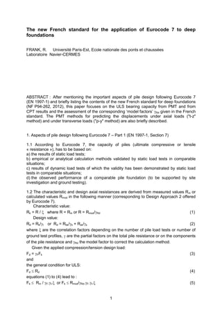
categories). The function fsol only depends on the type of soil (Figure 1).
Figure 1. Functions fsol for PMT rules (2012).
For this calculation model leading to the ultimate resistance of piles Rmod from PMT results
(PMT 2012), values of the model factor (noted Rd;1) have been derived. Figure 2 shows how
the value rd;1 = 1,13 was selected for piles of „group 1‟ (no injected piles; no chalk) for which
134 tests are available.
The model factors Rd;1 are given in Table 1. They are to be used with the correlation
factors („model pile‟ procedure) . In the case the „alternative procedure‟ of Eurocode 7 is
used (also called the „ground model‟ procedure), the French code requires introducing the
additional factor: Rd;2 = 1,1.
0
25
50
75
100
125
150
175
200
0 1 2 3 4 5 6 7
pl* [MPa]
fsol[kPa]
Clay and Silt
Sand and Gravel
Chalk
Marl and Calcareous Marl
Weathered Rock
4. 4
Figure 2. Distribution function of R/Rm for „group 1‟ (134 tests, no injected piles; no chalk),
Burlon et al. (2014). R = calculated resistance Rm = measured resistance.
Table 1. Values of the model factor R;d1 in the new French code for deep foundation
(AFNOR, 2012). PMT method.
R ;d1
Compression
R ;d1
Tension
All piles, excepted
injected piles and piles
embedded in chalk
1,15 1,4
Piles embedded in
chalk, excepted
injected piles
1,4 1,7
Injected piles 2,0 2,0
3.3 The CPT method for ultimate resistance calculation
CPT rules : base resistance
The base unit resistance is:
qp = qo + kc qce
where qo is the total vertical „at rest‟ pressure, qce is the equivalent cone resistance at the
base and kc is the bearing factor. kc is a function of soil type and pile class (there are 7
classes of piles). It varies between 0.15 and 0.5.
5. 5
CPT rules: shaft resistance
The unit limit friction is :
qs = fsol and qs ≤ qsmax
0,2 ≤ ≤ 2,25 and qsmax vary according to soil type and pile category (there are 20 pile
categories). The function fsol only depends on the type of soil (Figure 3).
Figure 3. Functions fsol for CPT rules (2012).
For the CPT calculation model of the ultimate resistance of piles Rmod, values of the model
factor (noted Rd;1) have been derived in a similar manner as for the PMT model. They are
given in Table 2. They are to be used with the correlation factors („model pile‟ procedure).
In the case the „alternative procedure‟ of Eurocode 7 is used (also called the „ground model‟
procedure), the French code requires introducing and additional factor Rd;2 = 1,1.
Table 2. Values of the model factor R;d1 in the new French code for deep foundation
(AFNOR, 2012). CPT method.
R ;d1
Compression
R ;d1
Tension
All piles, excepted
injected piles and piles
embedded in chalk
1,18 1,45
Piles embedded in
chalk, excepted
injected piles
1,45 1,75
Injected piles 2,0 2,0
3.4 Design value of the ULS compressive (or tensile) resistance
The design value Rd of the ULS compressive (or tensile) resistance calculated from ground
test results (PMT or CPT results or else), is derived from the characteristic resistance Rk and
by applying the resistance factor t (Design Approach 2 of Eurocode 7).
0
25
50
75
100
125
150
175
200
0 1 2 3 4 5 6 7
pl* [MPa]
fsol[kPa]
Clay and Silt
Sand and Gravel
Chalk
Marl and Calcareous Marl
Weathered Rock
6. 6
The following expressions are obtained, where Rmod is the calculated resistance (from the
ground test results) :
„Model pile‟ procedure :
Rd = Rk/t = Rmod/(R;d1..t), with the correlation factor
„Alternative‟ procedure (‟ground model‟) :
Rd = Rk/t = Rmod/(R;d1.R;d2.t), with R;d2 = 1,1
where the resistance factor is:
- for permanent and transient design situations:
t = 1,1 for the ultimate compressive resistance (bearing capacity) and t = 1,15 for the
ultimate tensile resistance;
- for accidental design situations:
t = 1,0 for the ultimate compressive resistance (bearing capacity) and t = 1,05 for the
ultimate tensile resistance;
- for seismic design situations:
t = 1,1 for the ultimate compressive resistance (bearing capacity) and t = 1,15 for the
ultimate tensile resistance.
It is to be noted that the French standard for piles also requires that, for serviceability limit
states (SLS), the axial loads be lower than the design value of the creep load (which is a
given proportion of the calculated characteristic resistance).
4. Displacement under axial loads ("t-z" method ) and transverse loads (“p-y” method)
In the French standard, the t-z curves for axial loads and the p-y curves for transverse loads
are derived from the PMT results and they make use, in particular, of the Ménard
pressuremeter modulus EM .
For the t-z curves, the model of Frank and Zhao (1982) is used. Figure 4 shows the t-z
curve (denoted s), as well as the base load – base displacement curve q-sp.
Figure 4. Model for t-z curves (Frank and Zhao, 1982).
The stiffnesses of these curves are,
- for fine grained soils:
k = 2.0 EM/B and kq = 11.0 EM/B
- for granular soils:
k = 0.8 EM/B and kq = 4.8 EM/B
Many examples show that the results obtained with this PMT model for deriving the load-
settlement of piles is quite satisfactory (see, for instance, Bustamante and Frank, 1999).
7. 7
As for the determination of the "p-y" curves from PMT results, the new French code
advocates the use of the traditional Ménard subgrade reaction modulus EsM, as a function of
EM, together with the limit pressure pl.
5. Conclusions and future developments
In accordance with Eurocode 7 the calculation methods for the bearing capacity of piles,
included in the new French standard, are based on the results of full scale load tests on
piles.
The new PMT rules for piles (PMT 2012) have been fully calibrated against the database
of more than 170 full scale static load tests on piles. Corresponding CPT rules have also
been calibrated against the results in the database.
The important role of displacements of foundations of structures is fully recognised in
Eurocode 7 and in the French standard. A displacement design approach might prove to be
more important than the traditional design based on the determination of the bearing capacity
and application of a safety factor.
Are we ready to base our SLS verifications solely on displacement assessments? … and
is the structural engineer also ready?
6. Bibliographical references
AFNOR (2012). “NF P 94 282. Justification des ouvrages géotechniques - Normes
d'application nationale de l'Eurocode 7 - Fondations profondes”. French Standard, AFNOR,
Paris.
Burlon S., Frank R., Baguelin F., Habert J., and Legrand S. (2014). “Model factor for the
bearing capacity of piles from pressuremeter test results – Eurocode 7 approach”.
Géotechnique, Volume 64, Issue 7, June 2014, 513 –525.
Bustamante M and Frank R (1999) “Current French design practice for axially loaded piles”.
Ground Engineering, March 1999, 38–44.