1. Touch and Step Potential Testing
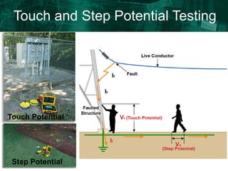
Touch Potential
Step Potential
2. Touch and Step Potential Testing
Why
Ground faults could reasonably be expected to occur near the area to be tested
or near equipment grounded by the ground to be tested
What you need
A 4 pole Ground Resistance Tester
Three auxiliary electrodes and test leads for Step Potential testing
Two auxiliary electrodes for Touch Potential testing
What you will Measure
The values determined by the instrument for both Step and Touch potential are in
ohms
What you will Calculate
Estimate the anticipated fault current and multiply it by the measured resistance to
calculate the potential voltage. The potential voltage will determine the degree of
danger.
3. The importance of testing and designing a
low resistance grounding system
Touch and Step Potential
If = Fault
Current
Note IEEE-80 recommends that
GPR (Ground potential rise) be
no more than 130V between
structures for safety reasons.
4. The importance of testing and designing a
low resistance grounding system
Step Potential: Difference in surface potential experienced by a
person’s feet bridging a one step distance of approximately 1
meter (3 feet) without contacting any other grounded surface.
The permissible
voltage thresholds
for Step Potential
can be higher than
for Touch
Potential.
5. Step Potential Test
1. Connect the E lead to the grounding system
Example:
Resistance reading (R) = 0.4Ω
Fault current (I) = 1000 Amps
Step potential (V) = R*I =
0.4*1000= 400 Volts
1 Meter (3 Ft)
3. Insert two electrodes 3 feet apart (the distance of a human step) at the approximate
location of the expected position of the person and attach the Es and S leads to them . All
electrodes should be in a straight line.
2. Insert the injector electrode at the approximate distance away from the grounding system
where the anticipated fault will occur and connect the H lead to it
4. Start the test using the 4-point Ground Test Mode and record the resistance reading
5. Estimate the expected fault current (I) and multiply it by the measured resistance reading (R)
to determine the step potential voltage V=I*R Example 1000 Amps
6. The importance of testing and designing a
low resistance grounding system
Touch Potential: Potential difference between grounded
metallic structure and the surface potential at the point where a
person is standing, while at the same time having hands in
contact with a grounded structure
In the Touch Potential case the currents flow almost directly
through and around the heart itself.
7. Touch Potential Test
1. Connect the E and Es leads to the metal object that would be touched
Example:
Resistance reading (R) = 0.2Ω
Fault current (I) = 1000 Amps
Touch potential (V) = R*I =
0.2*1000= 200 Volts
1 Meter (3 Ft)
3. Insert an electrode at the approximate location of the expected fault and connect the H
lead to it.
2. Insert an electrode approximately 1-meter (3 ft) from the object and connect the S lead
to it.
4. Start the test using the 4-point Ground Test Mode and record the resistance reading.
5. Estimate the expected fault current (I) and multiply it by the measured resistance
reading (R) to determine the touch potential voltage V=I*R Example 1000 Amps