1. 94
CHAPTER 4 / TRANSMISSION MEDIA
KEY POINTS
•
The transmission media that are used to convey information can be classi-fied
as guided or unguided. Guided media provide a physical path along
which the signals are propagated; these include twisted pair, coaxial cable,
and optical fiber. Unguided media employ an antenna for transmitting
through air, vacuum, or water.
•
Traditionally, twisted pair has been the workhorse for communications of
all sorts. Higher data rates over longer distances can be achieved with coax-ial
cable, and so coaxial cable has often been used for high-speed local area
network and for high-capacity long-distance trunk applications. However,
the tremendous capacity of optical fiber has made that medium more attrac-tive
than coaxial cable, and thus optical fiber has taken over much of the
market for high-speed LANs and for long-distance applications.
•
Unguided transmission techniques commonly used for information com-munications
include broadcast radio, terrestrial microwave, and satellite.
Infrared transmission is used in some LAN applications.
In a data transmission system, the
transmission medium
is the physical path between
transmitter and receiver. Recall from Chapter 3 that for
guided media
, electromag-netic
waves are guided along a solid medium, such as copper twisted pair, copper
coaxial cable, and optical fiber. For unguided media, wireless transmission occurs
through the atmosphere, outer space, or water.
The characteristics and quality of a data transmission are determined both by
the characteristics of the medium and the characteristics of the signal. In the case of
guided media, the medium itself is more important in determining the limitations of
transmission.
For unguided media, the bandwidth of the signal produced by the transmitting
antenna is more important than the medium in determining transmission character-istics.
One key property of signals transmitted by antenna is directionality. In gener-al,
signals at lower frequencies are omnidirectional; that is, the signal propagates in
all directions from the antenna. At higher frequencies, it is possible to focus the sig-nal
into a directional beam.
In considering the design of data transmission systems, key concerns are data
rate and distance: the greater the data rate and distance the better. A number of de-sign
factors relating to the transmission medium and the signal determine the data
rate and distance:
•
Bandwidth:
All other factors remaining constant, the greater the bandwidth
of a signal, the higher the data rate that can be achieved.
•
Transmission impairments:
Impairments, such as attenuation, limit the dis -
tance. For guided media, twisted pair generally suffers more impairment than
coaxial cable, which in turn suffers more than optical fiber.
•
Interference:
Interference from competing signals in overlapping frequency
2. bands can distort or wipe out a signal. Interference is of particular concern for
unguided media but is also a problem with guided media. For guided media,
STAL-04-093-128.I 4/5/03 10:54 AM Page 94
4.1 / GUIDED TRANSMISSION MEDIA
95
10
2
Frequency
(Hertz)
10
3
10
4
10
5
10
6
10
7
10
8
10
9
10
10
10
11
10
12
10
13
10
14
10
15
Power and telephone
Rotating generators
Musical instruments
Voice microphones
Microwav e
Radar
Microwave antennas
Magnetrons
Inf rared
Lasers
Guided missiles
Rangefinders
Radio
Radios and televisions
Electronic tubes
Integrated circuits
ELF
VF
ELF
Extremely low frequency
VF
Voice frequency
VLF
Very low frequency
LF
Low frequency
MF
Medium frequency
HF
High frequency
VHF
Very high frequency
UHF
Ultrahigh frequency
SHF
Superhigh frequency
EHF
Extremely high frequency
VLF
LF
MF
HF
VHF
3. UHF
SHF
EHF
Twisted pair
Coaxial cable
Visible
light
Optical
f iber
FM radio
and TV
AM radio
Terrestrial
and satellite
transmission
Wav elength
in space
(meters)
10
6
10
5
10
4
10
3
10
2
10
1
10
0
10
1
10
2
10
3
10
4
10
5
10
6
Figure 4.1
Electromagnetic Spectrum for Telecommunications
interference can be caused by emanations from nearby cables. For example,
twisted pairs are often bundled together and conduits often carry multiple
cables. Interference can also be experienced from unguided transmissions.
Proper shielding of a guided medium can minimize this problem.
•
Number of receivers:
A guided medium can be used to construct a point -to-point
link or a shared link with multiple attachments. In the latter case, each
attachment introduces some attenuation and distortion on the line, limiting
distance and/or data rate.
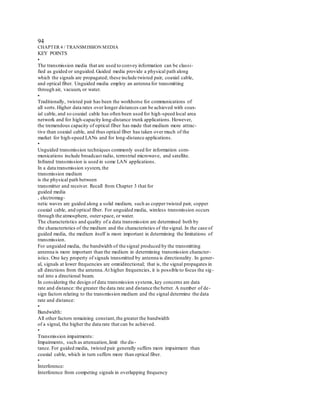
Figure 4.1 depicts the electromagnetic spectrum and indicates the frequencies
at which various guided media and unguided transmission techniques operate. In
this chapter we examine these guided and unguided alternatives. In all cases, we de-scribe
the systems physically, briefly discuss applications, and summarize key trans -
mission characteristics.
4.1 GUIDED TRANSMISSION MEDIA
For guided transmission media, the transmission capacity, in terms of either data
rate or bandwidth, depends critically on the distance and on whether the medium is
point-to-point or multipoint. Table 4.1 indicates the characteristics typical for the
common guided media for long-distance point-to-point applications; we defer a dis -
cussion of the use of these media for multipoint LANs to Part Four.
STAL-04-093-128.I 4/5/03 10:54 AM Page 95
96
CHAPTER 4 / TRANSMISSION MEDIA
The three guided media commonly used for data transmission are twisted pair,
coaxial cable, and optical fiber (Figure 4.2). We examine each of these in turn.
4. Twisted Pair
The least expensive and most widely used guided transmission medium is twisted pair.
Physical Description
A twisted pair consists of two insulated copper wires arranged in a regular spi-ral
pattern. A wire pair acts as a single communication link. Typically, a number of
these pairs are bundled together into a cable by wrapping them in a tough protec-tive
sheath. Over longer distances, cables may contain hundreds of pairs. The twist-ing
tends to decrease the crosstalk interference between adjacent pairs in a cable.
Neighboring pairs in a bundle typically have somewhat different twist lengths to re-duce
the crosstalk interference. On long-distance links, the twist length typically
varies from 5 to 15 cm. The wires in a pair have thicknesses of from 0.4 to 0.9 mm.
Applications
By far the most common transmission medium for both analog and digital sig-nals
is twisted pair. It is the most commonly used medium in the telephone network
and is the workhorse for communications within buildings.
In the telephone system, individual residential telephone sets are connected to
the local telephone exchange, or “end office,” by twisted-pair wire. These are re-ferred
to as
subscriber loops
. Within an office building, each telephone is also con-nected
to a twisted pair, which goes to the in-house private branch exchange (PBX)
system or to a Centrex facility at the end office. These twisted-pair installations were
designed to support voice traffic using analog signaling. However, by means of a
modem, these facilities can handle digital data traffic at modest data rates.
Twisted pair is also the most common medium used for digital signaling. For
connections to a digital data switch or digital PBX within a building, a data rate of
64 kbps is common. Twisted pair is also commonly used within a building for local
area networks supporting personal computers. Data rates for such products are
typically in the neighborhood of 10 Mbps. However, twisted-pair networks with data
rates of to 1 Gbps have been developed, although these are quite limited in terms of
Frequency Typical Typical Repeater
Range Attenuation Delay Spacing
Twisted pair 0 to 3.5 kHz 2 km
(with loading)
Twisted pairs 0 to 1 MHz 2 km
(mult i-pair cables)
Coaxial cable 0 to 500 MHz 1 to 9 km
Opt ical fiber 180 to 370 THz 0.2 to 40 km
5
s
>
km
0.5
dB
>
km
4
s
>
km
7
dB
>
km
@
10
MHz
5
s
>
km
3
5. dB
>
km
@
1kHz
50
s
>
km
0.2
dB
>
km
@
1kHz
Table 4.1
Point-to-Point Transmission Characteristics of Guided Media [GLOV98]
THz TeraHerz
=
10
12
Hz.
=
STAL-04-093-128.I 4/5/03 10:54 AM Page 96
4.1 / GUIDED TRANSMISSION MEDIA
97
(a) Twisted pair
(b) Coaxial cable
— Outer conductor is braided shield
— Inner conductor is solid metal
— Separated by insulat ing material
— Covered by padding
Light at less than
crit ical angle is
absorbed in jacket
Angle of
incidence
Angle of
reflect ion
Outer sheath
Insulat ion
Inner
conductor
— Glass or plast ic core
— Laser or light emitting diode
— Specially designed jacket
— Small size and weight
(c) Optical fiber
Core
Jacket
Cladding
Twist
length
— Separately insulated
— Twisted together
— Often "bundled" into cables
— Usually installed in building
during const ruction
Outer
conductor
Figure 4.2
Guided Transmission Media
the number of devices and geographic scope of the network. For long-distance ap-plications,
twisted pair can be used at data rates of 4 Mbps or more.
Twisted pair is much less expensive than the other commonly used guided
transmission media (coaxial cable, optical fiber) and is easier to work with.
Transmission Characteristics
Twisted pair may be used to transmit both analog and digital transmission. For
6. analog signals, amplifiers are required about every 5 to 6 km. For digital transmis -
sion (using either analog or digital signals), repeaters are required every 2 or 3 km.
Compared to other commonly used guided transmission media (coaxial cable,
optical fiber), twisted pair is limited in distance, bandwidth, and data rate. As
STAL-04-093-128.I 4/5/03 10:54 AM Page 97
98
CHAPTER 4 / TRANSMISSION MEDIA
10
7
10
6
10
5
10
4
10
8
10
7
10
6
10
5
10
15
10
12
1 THz
10
9
1 GHz
10
3
1 kHz
10
6
1 MHz
10
3
10
2
Frequency (Hz)
Attenuation (dB/km)
(a) Twisted pair (based on [REEV95])
0
5
10
15
20
25
30
Attenuation (dB/km)
0
0.5
1.0
1.5
2.0
2.5
3.0
26-AWG (0.4 mm)
24-AWG (0.5 mm)
22-AWG (0.6 mm)
19-AWG (0.9 mm)
0.5 mm
twisted pair
Frequency (Hz)
Attenuation (dB/km)
(b) Coaxial cable (based on [BELL90])
0
5
10
15
20
25
30
Attenuation (dB/km)
0
5
10
15
20
25
30
800 900 1000 1100 1200 1300 1400 1500 1600 1700
Wavelength in vacuum (nm)
(c) Optical fiber (based on [FREE02])
Frequency (Hz)
(d) Composite graph
typical optical
fiber
9.5 mm
coax
3/8" cable
(9.5 mm)
Figure 4.3
7. Attenuation of Typical Guided Media
Figure 4.3a shows, the attenuation for twisted pair is a very strong function of fre-quency.
Other impairments are also severe for twisted pair. The medium is quite sus -
ceptible to interference and noise because of its easy coupling with electromagnetic
fields. For example, a wire run parallel to an ac power line will pick up 60-Hz energy.
Impulse noise also easily intrudes into twisted pair. Several measures are taken to
reduce impairments. Shielding the wire with metallic braid or sheathing reduces in-terference.
The twisting of the wire reduces low-frequency interference, and the use
of different twist lengths in adjacent pairs reduces crosstalk.
For point-to-point analog signaling, a bandwidth of up to about 1 MHz is pos -
sible. This accommodates a number of voice channels. For long-distance digital
point-to-point signaling, data rates of up to a few Mbps are possible; for very short
distances, data rates of up to 1 Gbps have been achieved in commercially available
products.
Unshielded and Shielded Twisted Pair
Twisted pair comes in two varieties: unshielded and shielded. Unshielded
twisted pair (UTP) is ordinary telephone wire. Office buildings, by universal prac-tice,
are prewired with excess unshielded twisted pair, more than is needed for sim-ple
telephone support. This is the least expensive of all the transmission media
commonly used for local area networks and is easy to work with and easy to install.
Unshielded twisted pair is subject to external electromagnetic interference, in-cluding
interference from nearby twisted pair and from noise generated in the
STAL-04-093-128.I 4/5/03 10:54 AM Page 98
4.1 / GUIDED TRANSMISSION MEDIA
99
environment. A way to improve the characteristics of this medium is to shield the
twisted pair with a metallic braid or sheathing that reduces interference. This shield-ed
twisted pair (STP) provides better performance at higher data rates. However, it
is more expensive and more difficult to work with than unshielded twisted pair.
Category 3 and Category 5 UTP
Most office buildings are prewired with a type of 100-ohm twisted pair cable
commonly referred to as voice grade. Because voice-grade twisted pair is already in-stalled,
it is an attractive alternative for use as a LAN medium. Unfortunately, the
data rates and distances achievable with voice-grade twisted pair are limited.
In 1991, the Electronic Industries Association published standard EIA-568,
Commercial Building Telecommunications Cabling Standard
, which specifies the use
of voice-grade unshielded twisted pair as well as shielded twisted pair for in-building
data applications. At that time, the specification was felt to be adequate for the range
of frequencies and data rates found in office environments. Up to that time, the prin-cipal
interest for LAN designs was in the range of data rates from 1 Mbps to 16 Mbps.
Subsequently, as users migrated to higher-performance workstations and applications,
there was increasing interest in providing LANs that could operate up to 100 Mbps
over inexpensive cable. In response to this need, EIA-568-A was issued in 1995. The
new standard reflects advances in cable and connector design and test methods. It cov -
ers 150-ohm shielded twisted pair and 100-ohm unshielded twisted pair.
EIA-568-A recognizes three categories of UTP cabling:
•
Category 3:
UTP cables and associated connecting hardware whose transmis -
sion characteristics are specified up to 16 MHz
•
Category 4:
UTP cables and associated connecting hardware whose transmis -
sion characteristics are specified up to 20 MHz
•
8. Category 5:
UTP cables and associated connecting hardware whose transmis -
sion characteristics are specified up to 100 MHz
Of these, it is Category 3 and Category 5 cable that have received the most at -
tention for LAN applications. Category 3 corresponds to the voice-grade cable found
in abundance in most office buildings. Over limited distances, and with proper design,
data rates of up to 16 Mbps should be achievable with Category 3. Category 5 is a
data-grade cable that is becoming increasingly common for preinstallation in new
office buildings. Over limited distances, and with proper design, data rates of up to
100 Mbps should be achievable with Category 5.
A key difference between Category 3 and Category 5 cable is the number of
twists in the cable per unit distance. Category 5 is much more tightly twisted, with a
typical twist length of 0.6 to 0.85 cm, compared to 7.5 to 10 cm for Category 3. The
tighter twisting of Category 5 is more expensive but provides much better perfor-mance
than Category 3.
Table 4.2 summarizes the performance of Category 3 and 5 UTP, as well as the
STP specified in EIA-568-A. The first parameter used for comparison, attenuation,
is fairly straightforward. The strength of a signal falls off with distance over any
transmission medium. For guided media attenuation is generally exponential and
therefore is typically expressed as a constant number of decibels per unit distance.
STAL-04-093-128.I 4/5/03 10:54 AM Page 99
100
CHAPTER 4 / TRANSMISSION MEDIA
Attenuation (dB per 100 m) Near-end Crosstalk (dB)
Frequency Category 3 Category 5 150-ohm Category 3 Category 5 150-ohm
(MHz) UTP UTP STP UTP UTP STP
1 2.6 2.0 1.1 41 62 58
4 5.6 4.1 2.2 32 53 58
16 13.1 8.2 4.4 23 44 50.4
25
—
10.4 6.2
—
41 47.5
100
—
22.0 12.3
—
32 38.5
300
——
21.4
——
31.3
Table 4.2
Comparison of Shielded and Unshielded Twisted Pair
Table 4.3
Twisted Pair Categories and Classes
UTP Unshielded twisted pair
FTP Foil twisted pair
SSTP Shielded screen twisted pair
=
=
=
Near-end crosstalk as it applies to twisted pair wiring systems is the coupling
of the signal from one pair of conductors to another pair. These conductors may be
the metal pins in a connector or wire pairs in a cable. The near end refers to coupling
that takes place when the transmit signal entering the link couples back to the
receiving conductor pair at that same end of the link (i.e., the near transmitted sig-nal
is picked up by the near receive pair).
Since the publication of EIA-568-A, there has been ongoing work on the de-velopment
of standards for premises cabling, driven by two issues. First, the Gigabit
9. Ethernet specification requires the definition of parameters that are not specified
completely in any published cabling standard. Second, there is a desire to specify ca-bling
performance to higher levels, namely Enhanced Category 5 (Cat 5E), Catego-ry
6, and Category 7. Tables 4.3 and 4.4 summarize these new cabling schemes and
compare them to the existing standards.
Coaxial Cable
Physical Description
Coaxial cable, like twisted pair, consists of two conductors, but is constructed
differently to permit it to operate over a wider range of frequencies. It consists of a
hollow outer cylindrical conductor that surrounds a single inner wire conductor (Fig -
ure 4.2b). The inner conductor is held in place by either regularly spaced insulating
Category 3 Category 5 Category 6 Category 7
Class C Class D Category 5E Class E Class F
Bandwidth
16 MHz 100 MHz 100 MHz 200 MHz 600 MHz
Cable Type
UTP UTP/FTP UTP/FTP UTP/FTP SSTP
Link Cost
0.7 1 1.2 1.5 2.2
(Cat 5 1)
STAL-04-093-128.I 4/5/03 10:54 AM Page 100
igure 7.1
Transmission medium and physical layer
7.3
Figure 7.2
Classes of transmission media
7.5
Figure 7.3
Twisted-pair cable
7.7
Table 7.1
Categories of unshielded twisted-pair cables
7.8
Figure 7.5
UTP connector
7.9
Figure 7.6
UTP performance
10. 7.10
Figure 7.7
Coaxial cable
7.11
Table 7.2
Categories of coaxial cables
7.12
Figure 7.8
BNC connectors
7.14
Figure 7.10
Bending of light ray
7.15
Figure 7.11
Optical fiber
7.23
Figure 7.17
Electromagnetic spectrum for wireless communication
7.24
Figure 7.18
Propagation methods
7.25
Table 7.4
Bands
7.31