1. UNIT -2
Physical Layer:
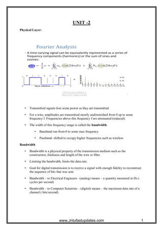
• Transmitted signals lose some power as they are transmitted.
• For a wire, amplitudes are transmitted mostly undiminished from 0 up to some
frequency f. Frequencies above this frequency f are attenuated (reduced).
• The width of this frequency range is called the bandwidth.
• Baseband run from 0 to some max frequency
• Passband- shifted to occupy higher frequencies such as wireless
Bandwidth
• Bandwidth is a physical property of the transmission medium such as the
construction, thickness and length of the wire or fiber.
• Limiting the bandwidth, limits the data rate.
• Goal for digital transmission is to receive a signal with enough fidelity to reconstruct
the sequence of bits that was sent.
• Bandwidth – to Electrical Engineers –(analog) means – a quantity measured in Hz (
cycles per second)
• Bandwidth – to Computer Scientists – (digital) means – the maximum data rate of a
channel ( bits/second)
www.Jntufastupdates.com 1
2. Transmission Media
Transmission Media – Guided
There are several types of cable which are commonly used with LANs. In some cases, a
network will utilize only one type of cable, other networks will use a variety of cable types.
The type of cable chosen for a network is related to the network’s topology, protocol, and
size. Understanding the characteristics of different types of cable and how they relate to other
aspects of a network is necessary for the development of a successful network.
www.Jntufastupdates.com 2
3. Unshielded Twisted Pair (UTP) Cable
Shielded Twisted Pair (STP) Cable
Coaxial Cable
Fiber Optic Cable
Unshielded Twisted Pair (UTP) Cable
Twisted pair cabling comes in two varieties: shielded and unshielded. Unshielded twisted pair
(UTP) is the most popular and is generally the best option for school networks.
Figure 2.1 Unshielded Twisted Pair
The quality of UTP may vary from telephone-grade wire to extremely high-speed cable. The
cable has four pairs of wires inside the jacket. Each pair is twisted with a different number of
twists per inch to help eliminate interference from adjacent pairs and other electrical devices.
The tighter the twisting, the higher the supported transmission rate and the greater the cost
per foot. The EIA/TIA (Electronic Industry Association / Telecommunication Industry
Association) has established standards of UTP and rated five categories of wire.
Type Use
Category 1 Voice Only (Telephone Wire)
Category 2 Data to 4 Mbps (LocalTalk)
Category 3 Data to 10 Mbps (Ethernet)
Category 4 Data to 20 Mbps (16 Mbps Token Ring)
Category 5 Data to 100 Mbps (Fast Ethernet)
Table Categories of Unshielded Twisted Pair
www.Jntufastupdates.com 3
4. Unshielded Twisted Pair Connector
The standard connector for unshielded twisted pair cabling is an RJ-45 connector. This is a
plastic connector that looks like a large telephone-style connector (See fig. 2.2). a slot allows
the RJ-45 to be inserted only one way. RJ stands for Registered Jack, implying that the
connector follows a standard borrowed from the telephone industry. This standard designates
which wire goes with each pin inside the connector.
Figure 2.2 RJ-45
Shielded Twisted Pair (STP) Cable
A disadvantage of UTP is that it may be susceptible to radio and electrical frequency
interference. Shielded twisted pair |(STP) is suitable for environments with electrical
interference; however, the extra shielding can make the cables quite bulky. Shielded twisted
pair is often used on networks using Token Ring topology.
Coaxial Cable
Coaxial cabling has a single copper conductor at its center. A plastic layer provides insulation
between the center conductor and the braided metal shield (See fig. 3). The metal shield helps
to block any outside interference from fluorescent lights, motors, and other computers.
Fig. 2.3 Coaxial cable
www.Jntufastupdates.com 4
5. Although coaxial cabling is difficult to install, it is highly resistant to signal interference. In
addition, it can support grater cable lengths between network devices than twisted pair cable.
The two types of coaxial cabling are thick coaxial and thin coaxial.
Thin coaxial cable is also referred to as thinnet. 10base2 refers to the specifications for thin
coaxial cable carrying Ethernet signals. The 2 refers to the approximate maximum segment
length being 200 meters. In actual fact the maximum segment length is 185 meters. Thin
coaxial cable is popular in school networks, especially linear bus networks.
Thick coaxial cable is also referred to as thicknet. 10base refers to the specifications for thick
coaxial cable carrying Ethernet signals. The 5 refers to the maximum segment length being
500 meters. Thick coaxial cable has an extra protective plastic cover that helps keep moisture
away from the center conductor. This makes thick coaxial a great choice when running longer
lengths in a linear bus network. One disadvantage of thick coaxial is that it does not bend
easily and is difficult to install.
2.1.3 Fiber Optic Cable
Fiber optic cabling consists of a center glass core surrounded by several layers of protective
materials. It transmits light rather than electronic signals eliminating the problem of electrical
interference.
This makes it ideal for certain environments that contain a large amount of electrical
interference. It has also made it the standard for connecting networks between buildings, due
to its immunity to the effects of moisture and lighting.
Fiber optic cable has the ability to transmit signals over much longer distances than coaxial
and twisted pair. It also has made it the standard for connecting networks between buildings,
due to its immunity to the effects of moisture and lighting.
Fiber optic cable has the ability to transmit signals over mush longer distances than coaxial
and twisted pair. It also has the capability to carry information at vastly greater speeds. This
capacity broadens communication possibilities to include services such as video conferencing
and interactive services. The cost of fiber optic cabling is comparable to copper cabling;
however it is more difficult to install and modify. 10BaseF refers to the specifications for
fiber optic cable carrying Ethernet signals.
Fig. 2.5 Fiber Optic Cable
www.Jntufastupdates.com 5
6. Facts about fiber optic cables:
Outer insulating jacket is made of Teflon or PVC.
Kevlar fiber helps to strengthen the cable and prevent breakage.
A plastic coating is used to cushion the fiber center.
Center (core) is made of glass or plastic fibers.
Fiber Optic Connector
The most common connector used with fiber optic cable is an ST connector. It is barrel
shaped, similar to a BNC connector. A newer connector, the SC, is becoming more popular.
It has a squared face and is easier to connect in a confined space.
Specification Cable Type Maximum length
10BaseT Unshielded Twisted Pair 100 meters
10Base2 Thin Coaxial 185 meters
10Base5 Thick Coaxial 500 meters
10BaseF Fiber Optic 2000 meters
100BaseT Unshielded Twisted Pair 100 meters
100BaseTX Unshielded Twisted Pair 220 meters
Table 2.2 Ethernet Cable Summary
2.2 Transmission Media – Unguided
Unguided transmission media is data signals that flow through the air. They are not guided or
bound to a channel to follow.
Unguided media transport electromagnetic waves without using a physical conductor. This
type of communication is often referred to as wireless communication. Signals are normally
broadcast through free space and thus are available to anyone who has a device receiving
them. Unguided signals can travel from the source to destination in several ways: ground
propagation, sky propagation, and line-of-sight propagation.
www.Jntufastupdates.com 6
7. In ground propagation, radio waves travel through the lowest portion of the atmosphere,
hugging the earth. These low-frequency signals emanate in all directions from the
transmitting antenna and follow the curvature of the planet. Distance depends on the amount
of power in the signal: The greater the power, the greater the distance. Ground waves have
carrier frequencies up to 2 MHz. AM radio is an example of ground wave propagation.
Fig. 2.6 Ground Wave Propagation
In sky propagation, higher frequency radio waves radiate upward into the ionosphere (the
layer of atmosphere where the particles exist as ions) where they are reflected back to the
earth. This type of transmission allows for greater distances with lower output power.
It is sometimes called double hop propagation. It operates in the frequency range of 30 – 85
MHz. Because it depends on the earth’s ionosphere, it changes with the weather and time of
day. The signal bounces off of the ionosphere and back to the earth. Ham radios operate in
this range. Other books called this Ionospheric propagation.
Fig. 2.7 Ionospheric Propagation
In line-of-sight propagation, very high-frequency signals are transmitted in straight lines
directly from antenna to antenna. Antennas must be directional, facing each other and either
tall enough or close enough together not to be affected by the curvature the earth. Line-of-
sight propagation is tricky because radio transmission cannot be completely focused.
www.Jntufastupdates.com 7
8. It is sometimes called space waves or tropospheric propagation. It is limited by the curvature
of the earth for ground-based stations (100 km, from horizon to horizon). Reflected waves
can cause promlems. Axamples are: FM radio, microwave and satellite.
Fig. 2.8 Line-of-sight Propagation
The section of the electromagnetic spectrum defined as radio waves and microwaves is
divided into eight ranges, called bands, each regulated by government authorities. These
bands are rated from very low frequency (VLF) to extremely high frequency (EHF).
Band Range Propagation Application
VLF (very low
frequency)
3-30 kHz Ground Long-range radio
navigation
LF (low frequency) 30-300 kHz Ground Radio beacons and
navigation locator
MF (middle
frequency)
300 kHz-3 MHz Sky AM radio
HF (high frequency) 3-30MHz Sky Citizens band (CB),
ship/aircraft
communication
VHF (very high
frequency)
30-300MHz Sky and line-of-
sight
VHF TV, FM radio
UHF (ultrahigh
frequency)
300 MHz-3 GHz Line-of-sight UHF TV, cellular
phones, paging,
satellite
SHF (superhigh
frequency)
3-30 GHz Line –of-sight Satellite
communication
EHF (extremely
high frequency)
30-300 GHz Line-of-sight Radar, satellite
Table 2.3 Bands
We can divide wireless transmission into three broad groups: radio waves, microwaves, and
infrared waves.
www.Jntufastupdates.com 8
9. 2.2.1 Radio Waves
Electromagnetic waves ranging in frequencies between 3 kHz and 1 GHz are normally called
radio waves.
Radio waves are omnidirectional. When antenna transmits radio waves, they are propagated
in all directions. This means that the sending and receiving antennas do not have to be
aligned. A sending antenna sends waves that can be received by any receiving antenna.
The omnidirectional property has a disadvantage too. The radio waves transmitted by one
antenna are susceptible to interference by another antenna that may send signals using the
same frequency or band.
Radio waves, particularly those of low and medium frequencies, can penetrate walls. This
characteristic can be both an advantage and disadvantage. It is an advantage because, for
example, an AM radio can receive signals inside a building. It is a disadvantage because we
cannot isolate a communication to just inside or outside a building.
2.2.2 Microwaves
Electromagnetic waves having frequencies between 1 and 300 GHz are called microwaves.
Microwaves are unidirectional. When an antenna transmits microwave waves, they can be
narrowly focused. This means that the sending and receiving antennas need to be aligned.
The unidirectional property has an obvious advantage. A pair of antennas can be aligned
without interfering with another pair of aligned antennas. The following describes some
characteristics of microwave propagation:
Microwave propagation is line-of-sight. Since towers with the mounted antennas need
to be in direct sight of each other. This also set a limit on the distance between
stations depending on the local geography. Towers that are far apart need to be very
tall. The curvature of the earth as well as other blocking obstacles does not allow two
short towers to communicate by using microwaves. Typically the line of sight due to
the Earth’s curvature is only 50 km to the horizon. Repeaters are often needed for
long-distance communication.
Very high frequency microwaves cannot penetrate walls. This characteristic can be a
disadvantage if receivers are inside the buildings.
The microwave band is relatively wide, almost 299 GHz. Therefore wider subbands
can be assigned, and a high data rate is possible.
Use of certain portions of the band requires permission from authorities.
2.2.3 Infrared Waves
Infrared waves, with frequencies from 300 GHz to 400 THz (wavelengths from 1 mm to 770
mm), can be used for short-range communication. Infrared waves, having high frequencies,
cannot penetrate walls. This advantageous characteristic prevents interference between one
system and another; a short-range communication system in one room cannot be affected by
another system in the next room. When we use our infrared remote control, we do not
www.Jntufastupdates.com 9
10. interfere with the use of the remote of our neighbors. However, this same characteristic
makes infrared signals useless for long-range communication. In addition, we cannot use
infrared waves outside a building because the sun’s rays contain infrared waves that can
interfere with the communication.
2.2.4 Satellite
Satellites are transponders (units that receive on one frequency and retransmit on another)
that are set in geostationary orbits directly over the equator. These geostationary orbits are 36,
000 km from the Earths’s surface. At this point, the gravitational pull of the Earth and the
centrifugal force of Earth’s rotation are balanced and cancel each other out. Centrifugal force
is the rotational force placed on the satellite that wants to fling it out into the space.
Fig. 2.9 Satellite Communication
The uplink is the transmitter of data to the satellite. The downlink is the receiver of data.
Uplinks and downlinks are also called Earth stations because they are located on the Earth.
The footprint is the “shadow” that the satellite can transmit to, the shadow being the area that
can receive the satellite’s transmitted signal.
Fig. 2.10 Uplink and Downlink
www.Jntufastupdates.com 10
11. Digital Modulation techniques
Digital-to-Analog signals is the next conversion we will discuss in this chapter. These
techniques are also called as Digital Modulation techniques.
Digital Modulation provides more information capacity, high data security, quicker system
availability with great quality communication. Hence, digital modulation techniques have a
greater demand, for their capacity to convey larger amounts of data than analog modulation
techniques.
There are many types of digital modulation techniques and also their combinations,
depending upon the need. Of them all, we will discuss the prominent ones.
ASK–AmplitudeShift Keying
The amplitude of the resultant output depends upon the input data whether it should be a
zero level or a variation of positive and negative, depending upon the carrier frequency.
FSK–FrequencyShift Keying
The frequency of the output signal will be either high or low, depending upon the input data
applied.
PSK–PhaseShift Keying
The phase of the output signal gets shifted depending upon the input. These are mainly of
two types, namely Binary Phase Shift Keying (BPSK) and Quadrature Phase Shift Keying
(QPSK), according to the number of phase shifts. The other one is Differential Phase Shift
Keying (DPSK) which changes the phase according to the previous value.
M-aryEncoding
M-ary Encoding techniques are the methods where more than two bits are made to transmit
simultaneously on a single signal. This helps in the reduction of bandwidth.
The types of M-ary techniques are −
M-ary ASK
M-ary FSK
M-ary PSK
Amplitude Shift Keying (ASK) is a type of Amplitude Modulation which represents
the binary data in the form of variations in the amplitude of a signal.
Any modulated signal has a high frequency carrier. The binary signal when ASK
modulated, gives a zero value for Low input while it gives the carrier
output for High input.
www.Jntufastupdates.com 11
12. The following figure represents ASK modulated waveform along with its input.
Frequency Shift Keying (FSK) is the digital modulation technique in which the frequency
of the carrier signal varies according to the digital signal changes. FSK is a scheme of
frequency modulation.
The output of a FSK modulated wave is high in frequency for a binary High input and is low
in frequency for a binary Low input. The binary 1s and 0s are called Mark and Space
frequencies.
The following image is the diagrammatic representation of FSK modulated waveform along
with its input.
www.Jntufastupdates.com 12
13. Phase Shift Keying (PSK) is the digital modulation technique in which the phase of the
carrier signal is changed by varying the sine and cosine inputs at a particular time. PSK
technique is widely used for wireless LANs, bio-metric, contactless operations, along with
RFID and Bluetooth communications.
Following is the diagrammatic representation of BPSK Modulated output wave along with
its given input.
Multiplexing is a technique by which different analog and digital streams of transmission
can be simultaneously processed over a shared link. Multiplexing divides the high capacity
medium into low capacity logical medium which is then shared by different streams.
Communication is possible over the air (radio frequency), using a physical media (cable),
and light (optical fiber). All mediums are capable of multiplexing.
When multiple senders try to send over a single medium, a device called Multiplexer divides
the physical channel and allocates one to each. On the other end of communication, a De-
multiplexer receives data from a single medium, identifies each, and sends to different
receivers.
FrequencyDivisionMultiplexing
When the carrier is frequency, FDM is used. FDM is an analog technology. FDM divides
the spectrum or carrier bandwidth in logical channels and allocates one user to each channel.
Each user can use the channel frequency independently and has exclusive access of it. All
channels are divided in such a way that they do not overlap with each other. Channels are
separated by guard bands. Guard band is a frequency which is not used by either channel.
www.Jntufastupdates.com 13
14. TimeDivisionMultiplexing
TDM is applied primarily on digital signals but can be applied on analog signals as well. In
TDM the shared channel is divided among its user by means of time slot. Each user can
transmit data within the provided time slot only. Digital signals are divided in frames,
equivalent to time slot i.e. frame of an optimal size which can be transmitted in given time
slot.
TDM works in synchronized mode. Both ends, i.e. Multiplexer and De-multiplexer are
timely synchronized and both switch to next channel simultaneously.
When channel A transmits its frame at one end,the De-multiplexer provides media to
channel A on the other end.As soon as the channel A’s time slot expires, this side switches
to channel B. On the other end, the De-multiplexer works in a synchronized manner and
provides media to channel B. Signals from different channels travel the path in interleaved
manner.
CodeDivisionMultiplexing
Code division multiplexing (CDM) is a multiplexing technique that uses spread spectrum
communication. In spread spectrum communications, a narrowband signal is spread over a
www.Jntufastupdates.com 14
15. larger band of frequency or across multiple channels via division. It does not constrict
bandwidth’s digital signals or frequencies. It is less susceptible to interference, thus providing
better data communication capability and a more secure private line.
Code Division Multiple Access
When CDM is used to allow multiple signals from multiple users to share a common
communication channel, the technology is called Code Division Multiple Access (CDMA).
Each group of users is given a shared code and individual conversations are encoded in a
digital sequence. Data is available on the shared channel, but only those users associated with
a particular code can access the data.
Concept
Each communicating station is assigned a unique code. The codes stations have the following
properties −
If code of one station is multiplied by code of another station, it yields 0.
If code of one station is multiplied by itself, it yields a positive number equal to the
number of stations.
The communication technique can be explained by the following example −
Consider that there are four stations w, x, y and z that have been assigned the codes cw , cx,
cyand cz and need to transmit data dw , dx, dy and dz respectively. Each station multiplies its
code with its data and the sum of all the terms is transmitted in the communication channel.
Thus, the data in the communication channel is dw . cw+ dx . cx+ dy . cy+ dz . cz
Suppose that at the receiving end, station z wants to receive data sent by station y. In order to
retrieve the data, it will multiply the received data by the code of station y which is dy.
data = (dw . cw+ dx . cx+ dy . cy+ dz . cz ) . cy
= dw . cw . cy + dx . cx . cy+ dy . cy . cy+ dz . cz .
cy
=0 + 0 + dy . 4 + 0 = 4dy
www.Jntufastupdates.com 15
16. Thus, it can be seen that station z has received data from only station y while neglecting the
other codes.
Orthogonal Sequences
The codes assigned to the stations are carefully generated codes called chip sequences or
more popularly orthogonal sequences. The sequences are comprised of +1 or –1. They hold
certain properties so as to enable communication.
The properties are –
A sequence has m elements, where m is the number of stations.
If a sequence is multiplied by a number, all elements are multiplied by that number.
For multiplying two sequences, the corresponding positional elements are multiplied and
summed to give the result.
If a sequence is multiplied by itself, the result is m, i.e. the number of stations.
If a sequence is multiplied by another sequence, the result is 0.
For adding two sequences, we add the corresponding positional elements.
Let us ascertain the above properties through an example.
Consider the following chip sequences for the four stations w, x, y and z −
[+1 -1 -1 +1], [+1 +1 -1 -1], [+1 -1 +1 -1] and [+1 +1 +1 +1]
Each sequence has four elements.
If [+1 -1 -1 +1] is multiplied by 6, we get [+6 -6 -6 +6].
If [+1 -1 -1 +1] is multiplied by itself, i.e. [+1 -1 -1 +1]. [+1 -1 -1 +1], we get +1+1+1+1 =
4, which is equal to the number of stations.
If [+1 -1 -1 +1] is multiplied by [+1 +1 -1 -1], we get +1-1+1-1 = 0
If [+1 -1 -1 +1] is added to [+1 +1 -1 -1], we get [+2 0 -2 0].
The commonly used orthogonal codes are Walsh codes.
www.Jntufastupdates.com 16