SlideShare a Scribd company logo
1 of 66
Download to read offline
Prof. B. M. DusaneUnit 1 : Heat Transfer
1
Fundamentals of Heat Transfer
1
2
3
4
Conduction:
A: Extended Surfaces B: Lumped System
Convection
A. Forced B. Natural
Heat Exchanger & Boiling
A: Heat Exchangers B: Boiling & Condensation
5 Radiation
Basics of Radiation, Laws, Thermal Shields
Basics & 1-D Steady State Heat Transfer, Insulations
Academic Year : 2020-21
Course : Heat Transfer
Code : YME503*
Mr. B. M. Dusane
Prof. B. M. DusaneUnit 1 : Heat Transfer
2
Overview on Contents: HEAT TRANSFER
Unit 1 Conduction:
a) Introduction and Basic Concepts
b) One dimensional steady state heat conduction without
heat generation
12 Lectures
Unit 2 Unit – II A. Boundary Conditions - Heat Generation
B. Extended Surfaces
C. and Transient Conduction
10 Lectures
Unit 3 Unit – III Convection
A. Forced
B. Natural
8 Lectures
Unit 4 Unit –
A. Heat Exchangers and
B. Phase Change Phenomenon- Boiling & Condensation
10 Lectures
Unit 5 Unit –V Radiation 8 Lectures
Prof. B. M. DusaneUnit 1 : Heat Transfer
3
Objectives of COURSE: HEAT TRANSFER
Objectives
1 To understand the important modes of heat transfer and their
applications.
2 To get acquainted with knowledge of fin selection and lumped heat
capacitance.
3 To understand the mechanism of convective heat transfer
4 To learn the various heat exchangers and their applications.
5 To determine the radiative heat transfer between surfaces.
Prof. B. M. DusaneUnit 1 : Heat Transfer
4
To differentiate different
modes of heat transfer
and their applications.
01
To estimate heat transfer
due to convection in
various applications.
03
To analyze the
performance of Parallel
and Counter flow heat
exchangers.
04
OUTCOMES of COURSE: HEAT TRANSFER
To analyse the
phenomenon of
conduction in Fins.
02
05
To interpret the
concept of thermal
radiation in various
geometries.
Prof. B. M. DusaneUnit 1 : Heat Transfer
5
Focal points Numerical Industrial Approach
I. Plane wall 5 Furnace wall & Temperature distributions along length
Ii Cylinder 3 Boilers- Fire Tube Boilers
Many applications when pipe carries hot/cold fluids
III. Sphere 2 Nuclear Power Plant
Pressure vessels Design, Petroleum Tankers
Iv. Variable
thermal
conductivity
- a) ISOTROPIC material
b) ANISOTROPIC material
c) Metals & non metals behavoiur
V. Critical radius of
Insulation
3 a) Why insulation is provided??
b) Need every time??
c) In which manner insulation will economical??
Experiments
1 Thermal conductivity of insulating
powder
Why ‘kin ‘ should be less?
How the arrangement is done with diff materials?
2 Composite Wall Why need of insertion of various material in composite wall ?
Temperature Distribution.?? HOW????
Unit – I Basics & 1 –D Steady State heat Conduction , Insulation
Prof. B. M. DusaneUnit 1 : Heat Transfer
6
Focal points Numerical Industrial Approach
I. Transient Heat
Conduction –
Lumped System
6 a) Medicals analysis – death of human & time measurement
b) Food process Industries- Potato, Chicken, Eggs, Burgers etc.
c) Response of Thermocouple.
II. Heat transfer through extended surface
Insulated Fin 2 1. Stirrer ( Spoon, handles of machineries..etc)
Infinite long 3 1.Extensions provided on the various tanks
Short Fin 1 1.Automobile fins
Why need of it??
How the optimization is done???
Experiments
3 PIN FIN APPARATUS
(Natural Convection)
How the various parameters govern on this??
4 PIN FIN APPARATUS
(Forced)
Why Natural / Forced system is adapted??
Unit – II Boundary Conditions Extended Surfaces and Transient Heat Conduction
Prof. B. M. DusaneUnit 1 : Heat Transfer
7
Focal points Numerical Industrial Approach
velocity & thermal
boundary layers
------------ 1. Macroscopic approach
2. Advanced Scope to study to CFD
Forced convection 7 1. In high pressure boilers:- Babcock and Wilcox,
Lamont , Velox, Benson Boilers etc
2. Forced Draught in Power plants etc.
Natural convection 5 1. Concepts of Cooling with practical examples.
2. Solar system: Fluid flows naturally.
Dimensionless
numbers
--------- 1. Significance & their roles.
Experiments
5. Natural Convection 1. To determine ‘hConv.’ in natural convection practically and
theoretically.
6. Forced Convection 1. Theoretical & Practical Approach.
2. How velocity governs on the heat flow??
7 Thermal conductivity of metal rod 1. How the fluid flowing will be affected on K and Q
Unit – III Convection
Prof. B. M. DusaneUnit 1 : Heat Transfer
8
Focal points Numerical Industrial Approach
Heat exchangers
Applications
& Remedies to
hurdles
---------------- 1. Industrial processes- textile & sugar industries..etc
2. Scaling & methods to avoid it.
LMTD Approach 4 1. How its easy to determine temp & analysis??
2. It fails when unknown parameters will be there.
NTU methods 4 1. Governing approach in industries.
2. Vastly used for analysis for their characteristics
Boiling &
condensations.
---------------- 1. Why bernaught flux taken into design consideration.
2. Dropwise condensation more preferable?? How??
Experiments
8 Critical Heat Flux 1. Nature of Curve & Study
9 Heat pipe 1. Advanced method in heat exchanger performance
Unit –IV Heat Exchangers and Phase Change Phenomenon
Prof. B. M. DusaneUnit 1 : Heat Transfer
9
Focal points Numerical Industrial Approach
Laws of
radiation
3 1. Nuclear Reactors & Shells
Radiation shape
factor
3 1. Why always cooking food in hemisphere pots e.g. . Bowls,
Pan???
2. Different collectors & efficiency due to Shape factor
Radiation
shields
2 1. Discussion on atomic power plant.
2. Thermo Flasks
3. Space Instruments etc
Experiments
10 Stefan Boltzmann apparatus 1. Why difference in TH & PR values.
11 Emissivity of a Test surface 1. Black body & gray body analysis
Unit –V Radiation
Prof. B. M. DusaneUnit 1 : Heat Transfer
10
Tools Status Effects
1. Question Bank and Class
Contents
Ready 1. Helps to cover quality & quantitative numericals
avoiding problem dictation.
2. Assignments 4 units 1. Help to traditional problem at least.
3. Practical approach In LAB during
conduction.
(Subjected Covid 19*)
1. Concepts & viva preparation.
4. Recall the theories ----- 1. Challenges to mini projects.
5. Expert Lecture
( By Prof N L Bhirud)
Radiation-basic concepts
Ready 1. Effective transformation of Radiation which will
help to secure more marks
6 Reference Books 10
00
00**
10
05
1. Heat & Mass Transfer- M M Rathore
2. Heat Transfer- S P Sukhatme
3. Heat & Mass Transfer – R C Sachdeva
4. Heat Transfer – R K Rajput
5. Heat Transfer – P K Nag
Prof. B. M. DusaneUnit 1 : Heat Transfer
11
1. Good Reference Book
2. Reading
3. Understanding
4. Doubts on time
1. Basic Laws
2. Basic terms
3. Numericals
1. Self Notes
2. Practice of
problem solving
• Conceptual
Learning
• Help to design
• Score
Methodology To Learn Heat Transfer
Prof. B. M. DusaneUnit 1 : Heat Transfer
12
Heat Transfer ??
• Heat is thermal energy in
transit due to a
temperature difference.
• Whenever there exists a
temperature difference Heat
Transfer MUST exist.
• One dimensional steady state
heat conduction: -
One dimensional steady state
heat conduction through a plane
wall, cylindrical wall and sphere,
Analogy between Heat flow and
electricity,
Conduction
• Occurs when a temperature gradient exists
through a solid or a stationary fluid (liquid or
gas).
• Fourier's law of conduction
Conveciton
• Occurs within a moving fluid, or between a solid
surface and a moving fluid, when they are at
different temperatures.
• Newton's law of cooling
Radiation
• Heat transfer between two surfaces (that are
not in contact), often in the absence of an
intervening medium.
• Stefan Boltzmann's Law
Prof. B. M. DusaneUnit 1 : Heat Transfer
13
Heat Transfer
Steady State Heat Transfer
1. T = f(x, y, z only)
Unsteady State Heat Transfer
1. T = f ( x, y, z and t-time)
Prof. B. M. DusaneUnit 1 : Heat Transfer
14
Important Laws of Heat Transfer
Fourier Law of heat conduction
1- D Case :
As,
dx
dT
AkQ 
dx
dT
A
Q

dTkdx
A
Q

Lets consider that Q flowing
through the wall.
Lets take integration and apply limits
 
2
10
T
T
L
dTkQ
Where
k = Thermal
conductivity of
material in
W/m.K
L – Thickness of
Wall
A – C/S Area
normal to heat
flow
Prof. B. M. DusaneUnit 1 : Heat Transfer
15
)( 12 TTkL
A
Q

We will get
L
TT
dx
dT )( 21 

)( 21 TT
L
Ak
Q 


CondR
T
Q
)(

)( 21 TT
L
Ak
Q 

Summary
)(
Ak
L
T
Q



Prof. B. M. DusaneUnit 1 : Heat Transfer
16
Newton’s Law of Cooling : Convection
)(  TT
A
Q
s
)(.  TTAhQ ss
s
s
Ah
TT
Q
.
1
)( 

ConvR
T
Q
)(

Stefan Boltzmann's Law of radiation :
4
)(TAQ S
4
TAQ S  
Black Body
Gray Body
Prof. B. M. DusaneUnit 1 : Heat Transfer
17
To Solve basic Numericals in Heat Transfer in Unit 1
Write your comment with answers.
Apply basic laws of Conduction/Convection / Radiation and
make suitable assumptions.
Draw Block diagram first and think mode of heat transfer
involved in the given numerical.
Read Problem twice and try to write given data correctly.
Prof. B. M. DusaneUnit 1 : Heat Transfer
18
Example 1. Determine the heat flow across a plane wall of 10 cm thickness with a constant
thermal conductivity of 8.5 W/mK when the surface temperatures are steady at 100°C and
30°C. The wall area is 3m2. Also find the temperature gradient in the flow direction.
Given Data :
T1 = 100°C,
T2 = 30°C,
L = 10 cm = 0.1 m,
k = 8.5 W/mK,
A = 3 m2.
conductionR
T
Q

1
kA
L
T
Q


35.8
1.0
)30100(


Q WQ 17850
T
1
T2
Q
L
According to Fourier's Law:
dX
dT
kAQ 
dX
dT
 35.817850 mC
dX
dT
/700
Prof. B. M. DusaneUnit 1 : Heat Transfer
19
2. A person sits in a room with surrounding air at 26°C and convection coefficient over the body
surface is 6 W/m2K. The walls in the room are at 5°C as the outside temperature is below
freezing. If the body temperature is 37°C, determine the heat losses by convection and
radiation. Assume F = 1.0 for radiation. Consider a surface area of 0.6 m2.
Given Data :
= 6 𝑊/𝑚2 𝑘
𝑇 𝐵𝑜𝑑𝑦 = 37℃
𝑇 ∞ = 26℃
𝑇 𝑊𝑎𝑙𝑙 = 5℃
𝐴 𝑠 = 0.6 𝑚2
According to Newton’s Law of Cooling :
)(  TTAhQ SSConv
WQ
Q
conv
Conv
6.39
)2637(6.06


According to Stefan Boltzmann’s Law of Radiation :
)(
44
WallSSRad TTAQ 
WQRad 99.110
WQTotal 59.150
Convection heat loss, we already
calculated:
WQconv 60.39
Now if summer condition is there then
temperature of wall is also becomes
26 °C radiation loss is given by:
)(
44
WallSSRad TTAQ  
WQrad 28.42
WQTotal 88.81
Prof. B. M. DusaneUnit 1 : Heat Transfer
20
3. A horizontal plate (K=30W/m. K) 600mm X 900mm X 30mm is mentioned at
3000 C. The air at 300C flows over the plate. If the convection co-efficient of air over
the plate is 22 w/m2. K & 250 W heat is lost from the plate by radiation, calculate
the bottom surface temperature of the plate.
Given data :
𝐿 × 𝑏 × ℎ = 0.6 𝑚 × 0.9 𝑚 × 0.03𝑚
𝑇𝑠 = 300°𝐶, 𝑇 ∞ = 30°𝐶
𝑂𝑢𝑡𝑠𝑖𝑑𝑒 𝐶𝑜𝑛𝑣𝑒𝑐𝑡𝑖𝑣𝑒 ℎ𝑒𝑎𝑡 𝑡𝑟𝑎𝑛𝑠. 𝑐𝑜𝑒𝑓𝑓. ℎ𝑜 = 22 𝑊/𝑚2
𝑘
𝑇ℎ𝑒𝑟𝑚𝑎𝑙 𝐶𝑜𝑛𝑑𝑢𝑐𝑡𝑖𝑣𝑖𝑡𝑦 𝑜𝑓 𝑚𝑎𝑡𝑒𝑟𝑖𝑎𝑙 𝑘 = 30 𝑊/𝑚𝐾
Thickness of Plate 𝐿 = 0.03𝑚
𝑄 𝑅𝑎𝑑 = 250 𝑊.
𝑇 ∞ = 30°𝐶
ℎ𝑜 = 22 𝑊/𝑚2
𝑘
0.6m
0.03m
Q cond.
𝑄 𝑅𝑎𝑑
𝑄 𝑐𝑜𝑛𝑣
Assumptions:
1. 1-D Steady State heat conduction without heat generation.
2. Thermal properties remains constant.
Prof. B. M. DusaneUnit 1 : Heat Transfer
21
𝑇 ∞ = 30°𝐶
ℎ𝑜 = 22 𝑊/𝑚2
𝑘
0.6
m
0.
03
m
Q
cond.
𝑄 𝑅𝑎𝑑
𝑄 𝑐𝑜𝑛𝑣
Analysis:
Area of surface of the plate :
𝐴𝑠 = 0.6 m x 0.9 m
𝐴𝑠 = 0.54 m2
According to Fourier’s Law of
conduction:
)( Sbottom
c
Cond TT
L
Ak
Q 


)300(
03.0
54.030


 bottomCond TQ
…..Eq (A)
By putting all values in the above equation :
By Energy balance Equation we can write:
Rate of Heat Conduction = [ Rate of Heat Convection
+ rate of Heat Radiation ]
)( Sbottom
c
Cond TT
L
Ak
Q 


)300(
03.0
54.030


 bottomCond TQ
)( Sbottom
c
Cond TT
L
Ak
Q 


)300(
03.0
54.030


 bottomCond TQ
Prof. B. M. DusaneUnit 1 : Heat Transfer
22
5. An uninsulated steam pipe passes through a room in which the air and walls
are at 25°C.The outside diameter of the pipe is 70 mm, and its surface
temperature and emissivity are 200C and 0.8, respectively. What are the
surface emissive power and irradiation? If the coefficient associated with free
convection heat transfer from the surface to the air is 15 W/m2 K, what is the
rate of heat loss from the surface per unit length of pipe? (QB- 5 – Short)
4. A refrigerator stand in a room where the temp of air is 21° C and surface
temp at outside of the cover of system is 16 °C. The sides are 30 mm thick and
thermal conductivity of material 0.1 w/mk. Outside heat transfer coefficient is
10 w/m2k. Assuming that heat flow is one dimensional conduction through the
sides , calculate heat flow rate and inside temp of refrigerator system.
Prof. B. M. DusaneUnit 1 : Heat Transfer
23
6. An immersion water heater of a surface area 0.1 m2 and rating of 1
KW is design to operate fully submerged in water. Estimate the surface
temp of heater when water temp is at 40 °C and heat transfer coefficient
300 w/m2k. IF this heater by mistake use in air at 40 °C. with h of 9
w/m2k what will be surface tempt?
Prof. B. M. DusaneUnit 1 : Heat Transfer
24
• Material Properties: The property specific heat Cp as a measure of a material’s ability to store
thermal energy. For example, Cp 4.18 kJ/kg .
• Defination: The thermal conductivity k is a measure of a material’s ability to conduct heat.
• Thermal conductivity of a material can be defined as the rate of heat transfer through a unit
thickness of the material per unit area per unit temperature difference.
• What it indicates? – High value ? And Low Value of Thermal Conductivity.
• Why to study ? Selection of Material, Applications.
• Types of Material :
• A) ISOTROPIC : Thermal Conductivity does not vary with change indirection.
• B) ANISOTROPIC : Thermal conductivity depend upon the direction of flow
Prof. B. M. DusaneUnit 1 : Heat Transfer
25
• Thermal conductivity of a material is defined as the rate of heat transfer
through a unit thickness of the material per unit area per unit temperature
difference.
• The thermal conductivity of a material is a measure of how fast heat will
flow in that material.
• A large value for thermal conductivity indicates that the material is a good
heat conductor,
• A low value indicates that the material is a poor heat conductor or
insulator.
THERMAL CONDUCTIVITY
Prof. B. M. DusaneUnit 1 : Heat Transfer
26
• Figure shows the range of thermal conductivity for various states of matter at
normal temperature and pressure.
Reference : Heat and Mass Transfer: Fundamentals & Applications
Yunus A. Cengel, Afshin J. Ghajar, McGraw-Hill, 2011
Prof. B. M. DusaneUnit 1 : Heat Transfer
27
A solid may comprised free electrons and of atoms bound in a periodic arrangement called
the lattice. Accordingly, transport of thermal energy is due to two effects:
the migration of free electrons and
lattice vibrational waves.
These effects are additive, such that the thermal conductivity k is the sum of the electronic
component ke and the lattice component kl
k = ke + kl
where, ke is inversely proportional to the electrical resistivity ρe .
For pure metals, which are of low ρe, ke is much larger than kl .
For alloys, which are of substantially larger ρe, the contribution of kl to k is no longer
negligible.
For non-metallic solids, k is determined primarily by kl , which depends on the frequency
of interactions between the atoms of the lattice.
Prof. B. M. DusaneUnit 1 : Heat Transfer
28
Reference : Heat and Mass Transfer: Fundamentals & Applications
Yunus A. Cengel, Afshin J. Ghajar, McGraw-Hill, 2011
• Thermal insulation systems are comprised of low thermal conductivity materials
combined to achieve an even lower system thermal conductivity.
• In fiber-, powder-, flake-type insulations, the solid material is finely dispersed
throughout an air space to achieve effective thermal conductivity.
Effective thermal conductivity of such systems depends on
1. the thermal conductivity
2. surface radiative properties of the solid material,
3. the nature and volumetric fraction of the air or void space.
4. A special parameter of the system is its bulk density (solid mass/total volume),
which depends strongly on the manner in which the solid material is
interconnected
INSULATION SYSTEMS
Prof. B. M. DusaneUnit 1 : Heat Transfer
29
• Liquid : Thermal Conductivity decreases with increase in Temp.
• Exceptional case : Water & Glycerine.
• In Liquid K is function of Molecular weight and independent of Pressure.
• Solid (Metal) : two effects: the lattice vibrational waves induced by the
vibrational motions & Free Electrons.
• Effect of Temperature : As T ↑ , Thermal conductivity decreases in Metal
• Exceptional case : Mercury
• Solid ( Non-metal) : Absence of free electrons.
• No of collisions increase with increase in temperature.
• As T ↑ Then , Thermal conductivity increases in Non- Metal
Prof. B. M. Dusane , Dept. of Mechanical Engineering, S.O.E.T., Sandip University Nashik
Prof. B. M. DusaneUnit 1 : Heat Transfer
30
• Gases : Thermal Conductivity increases with increase in temperature.
• Transfer of energy due to continuous random motion of molecules.
• K is function of square root of absolute temperature.
• Affected by humidity and pressure.
• Determination of Thermal Conductivity
(k):
By using Fourier's law of heat conduction we can
calculate the value of k practically.
Q=
W
L
T
1
T
2
Heater
Coil
Prof. B. M. DusaneUnit 1 : Heat Transfer
31
Reference : Heat and Mass Transfer: Fundamentals & Applications
Yunus A. Cengel, Afshin J. Ghajar, McGraw-Hill, 2011
Prof. B. M. DusaneUnit 1 : Heat Transfer
32
Prof. B. M. DusaneUnit 1 : Heat Transfer
33
• Material property that appears in the transient heat conduction analysis is the
thermal diffusivity, which represents how fast heat diffuses through a material.
• The thermal conductivity k represents how well a material conducts heat, and the
heat capacity Cp represents how much energy a material stores per unit volume.
• Therefore, the thermal diffusivity of a material can be viewed as the ratio of the heat
conducted through the material to the heat stored per unit volume.
capacityHeat
ductivityThermalCon


PC
k

 
NOTE:
1. Materials of large α will respond quickly to changes in their thermal environment
2. Materials of small α will respond more sluggishly to reach new equilibrium condition.
Prof. B. M. DusaneUnit 1 : Heat Transfer
34
Thermal Resistance
1. There exists an analogy between the diffusion of heat and electrical charge.
2. Thermal resistance may be associated with the conduction of heat in the same fashion as
an electrical resistance is associated with the conduction of electricity.
3. Defining resistance as the ratio of a driving potential to the corresponding transfer rate
4. it follows from Equation - that the thermal resistance for conduction is
(a)
Similarly, for electrical conduction, Ohm's law provides an electrical resistance of the
form
(b)
 
cond
1 2s, s,
t ,
x
T T L
R
q kA

 
 1 2s, s,
e
E E L
R
l A

 
Prof. B. M. DusaneUnit 1 : Heat Transfer
35
Therefore,
• the rate of heat transfer through a plane wall corresponds to the electric current
• the thermal resistance corresponds to electrical resistance and
• the temperature difference corresponds to voltage difference across the plane wall.
(Figure.)
Figure : Analogy Between Thermal And Electrical Resistance Concepts
Prof. B. M. DusaneUnit 1 : Heat Transfer
36
Conduction resistance of the wall: Thermal
resistance of the wall against heat
conduction.
Thermal resistance of a medium depends
on the geometry and the thermal properties
of the medium.
Electrical resistance
Fig :Analogy between thermal and electrical
resistance concepts.
rate of heat transfer (Q) electric current (I)
thermal resistance R  electrical resistance R
temperature difference ∆T  voltage difference ∆V
Reference : Heat and Mass Transfer: Fundamentals & Applications
Yunus A. Cengel, Afshin J. Ghajar, McGraw-Hill, 2011
ELECTRICAL ANALOGY
c
e
A
L
R



Prof. B. M. DusaneUnit 1 : Heat Transfer
37
ELECTRICAL ANALOGY
CondR
T
Q
)(

)( 21 TT
L
Ak
Q 


Summary
)(
Ak
L
T
Q



Convection Case : R convConduction Case : R cond
)( 21 TTAhQ s 
TAhQ s  conv
s
R
T
Ah
T
Q





1
Prof. B. M. DusaneUnit 1 : Heat Transfer
38
The thermal resistance network for heat transfer through a plane wall subjected to convection on
both sides, and the electrical analogy.
Prof. B. M. DusaneUnit 1 : Heat Transfer
39
Multilayer Plane Walls
The thermal resistance network for heat transfer
through a two-layer plane wall subjected to
convection on both sides.
Reference : Heat and Mass Transfer: Fundamentals & Applications
Yunus A. Cengel, Afshin J. Ghajar, McGraw-Hill, 2011
Prof. B. M. DusaneUnit 1 : Heat Transfer
40
x=0 x=L
Too 2,
Too 1, Too 2,
Too 1,
Ts,1
Ts,2
h2h1
Hot Fluid Cold Fluid
q
x
Too 1, Ts,2 Too 2,Ts,1
1
h1 A
L
k A
1
h2A
x=0 x=L
Too 2,
Too 1, Too 2,
Too 1,
Ts,1
Ts,2
h2h1
Hot Fluid Cold Fluid
LBLA LC
q
x
Too 1, Ts,4 Too 4,Ts,1 T2 T3
1
h1 A
L
kA A
A L
kB A
B L
kC A
C
1
h4A
 1 4
1 4
1 1
, ,
x
CA B
A B C
T T
q
LL L
h A k A k A k A h A
 

                              
     1 1 1 2 2 2
1 2
1 1
, s, s, s, s, ,
x
T T T T T T
q
L
h A kA h A
   
  
Prof. B. M. DusaneUnit 1 : Heat Transfer
41
HEAT CONDUCTION IN CYLINDERS AND SPHERES
A long cylindrical pipe (or spherical shell) with specified
inner and outer surface temperatures T1 and T2.
Reference : Heat and Mass Transfer: Fundamentals & Applications
Yunus A. Cengel, Afshin J. Ghajar, McGraw-Hill, 2011
Prof. B. M. DusaneUnit 1 : Heat Transfer
42
A spherical shell with specified inner and
outer surface temperatures T1 and T2.
Reference : Heat and Mass Transfer: Fundamentals & Applications
Yunus A. Cengel, Afshin J. Ghajar, McGraw-Hill, 2011
Prof. B. M. DusaneUnit 1 : Heat Transfer
43
1-D STEADY STATE HEAT Conduction
without heat generation Numericals
and Applications:
A. Rectangular System:
• Application of Walls
• Need to estimate thickness or width or
suitable material for a given application.
• Need to find Thermal Conductivity & Select
the specific material
B. Cylindrical System
• Steam Pipes, heat exchanger's tube, Coils
• Wires,
• Pressure Vessels
C. Sphere:
• Nuclear Reactor, Combustion chambers
Resistance of different Entities :
1. Rectangular /Square (Wall)
AK
L
RWall


2. Cylindrical System :
LK
r
r
RCylinder








2
ln
1
2
3. Spherical System :
21
)12
4
(
rKr
rr
RSphere



Prof. B. M. DusaneUnit 1 : Heat Transfer
44
Objectives
To derive the three dimensional heat diffusion equation in Cartesian co-ordinates from first
principle and various boundary and initial conditions are stated.
THE HEAT DIFFUSION EQUATION
A major objective in a conduction analysis is to determine the temperature field in a medium
resulting from conditions imposed on its boundaries.
We now consider the manner in which the temperature distribution can be determined.
We define a differential control volume, identify the relevant energy transfer processes, and
introduce the appropriate rate equations.
 The result is a differential equation whose solution, for prescribed boundary conditions,
provides the temperature distribution in the medium.
Prof. B. M. DusaneUnit 1 : Heat Transfer
45
To determine the differential equation whose solution, for prescribed boundary conditions,
provides the temperature distribution in the medium.
Consider,
• a homogenous medium
• with no bulk motion and
• temperature distribution T(x,y,z)
Consider a infinitesimally small control volume dx.dy.dz , as shown in Figure.2
Figure 2. Differential Control Volume For Conduction
Analysis In Cartesian Coordinates
Prof. B. M. DusaneUnit 1 : Heat Transfer
46
The conduction heat rates perpendicular to each of the control surfaces at the x, y and z
coordinate locations are indicated by the terms qx, qy , and qz , respectively. The conduction
heat rates at the opposite surfaces can then be expressed as a Taylor series expansion
where, neglecting higher order terms,
(2.9a)
(2.9b)
(2.9c)
Equation 2.9a simply states that the x component of the heat transfer rate at x+dx is equal to the
value of this component at x plus the amount by which it changes with respect x times dx.
stE qdxdydz
Within the medium there may also be an energy source term. This term is represented as
(2.10)









 dx
x
Q
QQ x
xdxx









 dy
y
Q
QQ
y
ydyy









 dz
z
Q
QQ z
zdzz
where is the rate at which energy is generated per unit volume of the
medium (W/m3).
There may occur changes in the amount of the internal thermal energy stored
by the material in the control volume. The energy storage term may be
expressed as
(2.11)
where is the time rate of change of the thermal (sensible) energy of the
medium per unit volume.
The general form of the conservation of energy is
(2.12)
(2.13)
q
st p
T
E C dxdydz
t




p
T
C
t



in g out stE E E E  
in x y zE q q q  
(2.14)
substituting Equations 2.9, 2.13 and 2.14 in Equation 2.12, we obtain
(2.15)
substituting from Equation 2.9, it follows that
(2.16)
The conduction heat rates is evaluated from Fourier's law
(2.17a)
(2.17b)
(2.17c)
out x dx y dy z dzE q q q    
x y z x dx y dy z dz p
T
q q q q dxdy dz q q q C dxdy dz
t
  

      

yx z
p
qq q T
dx dy dz qdxdy dz C dxdy dz
x y z t

  
    
   
x
T
q k dydz
x

 

y
T
q k dxdz
y

 

z
T
q k dxdy
z

 

where each heat flux component has been multiplied by an appropriate control
surface area to obtain the heat transfer rate.
Substituting Equations 2.17 into 2.16 and dividing out the dimensions of the
control volume ( dx dy dz) , we obtain
(2.18)
Equation 2.18 is the general form of the heat diffusion equation in Cartesian
coordinates.
From the solution of this heat equation, we can obtain the temperature
distribution T(x,y,z) as a function of time.
If the thermal conductivity is a constant, the heat equation is
(2.19)
Where is the thermal diffusivity.
Under steady-state conditions , there can be no change in the amount of energy
storage; hence equation 2.18 reduces to
p
T T T T
k k k q C
x x y y z z t

          
                 
2 2 2
2 2 2
1T T T q T
k tx y z 
   
   
  
p
k
C



(2.20)
If the heat transfer is one dimensional (e.g., in the x direction) and there is no
energy generation , Equation 2.20 reduces to
(2.20a)
The most important implication of this result is that under steady state, one
dimensional conditions with no energy generation, the heat flux is a constant in
the direction of heat transfer
0
T T T
k k k q
x x y y z z
         
                
0
d dT
k
dx dx
 
 
 
Prof. B. M. DusaneUnit 1 : Heat Transfer
51
Application of Wall Design
Que. 1. An exterior wall of house may be approximated
by 0.1 m Layer of common brick (k= 0.7 W/mK) followed
by a 0.04 m layer of gypsum plaster having k = 0.48
W/mK. What thickness of loosely packed rock wool
insulation (k= 0.065 W/mK) should be added to reduce
heat loss through the wall by 80%?
Given Data :
Thickness of common Brick : 𝐿 𝐴
= 0.1 m
Thickness of Gypsum : 𝐿 𝐵
= 0.04 m
Thickness of Rock-wool (say) : 𝐿 𝐶
= X in m.
Thermal Conductivity of common Brick : 𝐾 𝐴
= 0.7 W/mK
Thermal Conductivity of gypsum :𝐾 𝐵
= 0.48 W/mK
Thermal Conductivity of Rock-wool : 𝐾 𝐶
= 0.065 W/mK
Case 1 : Q With Common Brick & Gypsum
Case 2: Q with all 3 types of material mentioned above
Assumptions:
1. 1-D Steady State heat conduction without heat
generation.
2. Thermal properties remains constant.
3. Area is considered as 1 sq. metre. (If necessary)
4. Contact resistance is neglected
Case 1 : Q with Brick and gypsum:
WallR
T
Q

1
BA RR
T
Q


1
BA RR
T
Q


1
48.0
04.0
7.0
1.01



TA
Q
)(4210.41 TAQ 
On Solving, we get
……… (A)
Prof. B. M. DusaneUnit 1 : Heat Transfer
52
Case 2: When Rockwool is added and will have 3 materials
R
T
Q


2
CA RRR
T
Q



B
2
C
C
B
B
A
A
K
L
K
L
K
L
TA
Q


2
065.048.0
04.0
7.0
1.02
Lc
TA
Q



065.0
22619.0
2
CL
TA
Q



But as per given condition , heat loss should be
reduced by 80% so we can write :
).......(2.0
%20
12
12
BQQ
QQ


)(4210.4
065.048.0
04.0
7.0
1.0
TA
Lc
TA



By putting values from equation (A) & (B)
On solving this equation, we will get value of Lc
mmmLC 8.580588.0 
Thus , the thickness of Rockwool should be 58.8 mm.
Prof. B. M. DusaneUnit 1 : Heat Transfer
53
Que 2: An ice box (20 cm × 20 cm × 10 cm height) is
filled with 3 Kg of ice at 0°C. The bottom and all vertical
sides are well insulated. The top cover of the box is 1
cm thick and is made up of a with K = 0.33 W/mK. The
cover is exposed to ambient air at 25°C with h = 10
W/m2
K. The heat transfer coefficient between inner
surface of cover and air inside the box is 8 W/m2
K.
Calculate the time required for the ice in the box to
melt completely.
Take latent heat of fusion of ice = 330 kJ/kg.
Given data :
𝐿 × 𝑏 × ℎ = 0.2 𝑚 × 0.2 𝑚 × 0.1𝑚
𝑚 𝑖𝑐𝑒
= 3 𝑘𝑔, 𝑇0 = 0°𝐶, 𝑇 ∞ = 25°𝐶
𝑂𝑢𝑡𝑠𝑖𝑑𝑒 𝐶𝑜𝑛𝑣𝑒𝑐𝑡𝑖𝑣𝑒 ℎ𝑒𝑎𝑡 𝑡𝑟𝑎𝑛𝑠. 𝑐𝑜𝑒𝑓𝑓. ℎ𝑜 = 10 𝑊/𝑚2
𝑘
𝐼𝑛𝑠𝑖𝑑𝑒 𝐶𝑜𝑛𝑣𝑒𝑐𝑡𝑖𝑣𝑒 ℎ𝑒𝑎𝑡 𝑡𝑟𝑎𝑛𝑠. 𝑐𝑜𝑒𝑓𝑓. ℎ𝑖 = 𝑊/𝑚2
𝑘
𝑇ℎ𝑒𝑟𝑚𝑎𝑙 𝐶𝑜𝑛𝑑𝑢𝑐𝑡𝑖𝑣𝑖𝑡𝑦 𝑜𝑓 𝑚𝑎𝑡𝑒𝑟𝑖𝑎𝑙 (𝑘) = 0.33 𝑊/𝑚𝐾
𝐿𝑎𝑡𝑒𝑛𝑡 ℎ𝑒𝑎𝑡 𝑜𝑓 𝑓𝑢𝑠𝑖𝑜𝑛 𝑜𝑓 𝑖𝑐𝑒 ℎ 𝑓𝑔
= 330 𝐾𝐽/𝐾𝑔
Assumptions:
1. 1-D Steady State heat conduction without heat
generation.
2. Thermal properties remains constant.
3. Material is isotropic ie. K remains constant in all
directions.
4. Contact resistance is neglected
Thickness of
Cover
ICE
Application of Refrigerator-Cover
Prof. B. M. DusaneUnit 1 : Heat Transfer
54
As surface area of cover = 0.2 x 0.2 m = 0.04 m2
𝑇𝑜𝑡𝑎𝑙 𝑟𝑒𝑠𝑖𝑠𝑡𝑎𝑛𝑐𝑒 𝑖𝑛 𝑡ℎ𝑒 𝑠𝑦𝑠𝑡𝑒𝑚 = 3
Σ 𝑅 = 𝑅 𝐶𝑜𝑛𝑣1 +
𝑅 𝐶𝑜𝑛𝑑 + 𝑅 𝑐𝑜𝑛𝑣2
AhAK
L
Ah
R
io 





11
𝐻𝑒𝑎𝑡 𝑇𝑟𝑎𝑛𝑠𝑓𝑒𝑟 𝑟𝑎𝑡𝑒 ,
R
TT
Q io



WQ 917.3
3826.6
)025(



AhAK
L
Ah
R
io 





11







8
1
33.0
01.0
10
1
04.0
1
R
WKR /3826.6
Now energy required to melt ice of 3 kg :
3303 fgiceMelt hmQ
KJQMelt 990
Time to melt ice can be calculated by :
Q
Q
t Melt

hourst 207.70sec1074.252 3

917.3
990
t
dayst 3
Prof. B. M. DusaneUnit 1 : Heat Transfer
55
Que.3. A circular plate heater (diameter 20 cm) is
inserted between two circular plates (diameter 20
cm), slab A is 3 cm thick (k = 55 W/mK) and slab B is
1.5 cm thick (k = 0.18 W/mK). The outside heat
transfer coefficient on sides of A and B are 200 and 65
W/m2
K respectively. The temperature of surrounding
air is 30°C. If the rating of heater is 2kW, find : A)
maximum temp. in the system. B)Outer surface temp.
of two sides. C) Draw equivalent electrical circuit of
the system.
Diameter of heater : d = 20 cm = 0.2 m
𝐴𝑟𝑒𝑎 𝑜𝑓 ℎ𝑒𝑎𝑡𝑒𝑟 =
𝜋
4
× 𝑑 2
= 0.0314 m2
𝑇ℎ𝑖𝑐𝑘𝑛𝑒𝑠𝑠 𝑜𝑓 𝑠𝑙𝑎𝑏 𝐴 = 3𝑐𝑚 = 0.03𝑚 𝑎𝑛𝑑 𝐾𝐴 = 55𝑊/𝑚𝐾
Thickness of slab B =1.5 cm = 0.015m and KB
= 0.18W/mK
𝐶𝑜𝑛𝑣𝑒𝑐𝑡𝑖𝑣𝑒 ℎ𝑒𝑎𝑡 𝑡𝑟𝑎𝑛𝑠. 𝑐𝑜𝑒𝑓𝑓. 𝐴 𝑠𝑖𝑑𝑒 ℎ𝐴 = 200 𝑊/𝑚2
𝑘
𝐶𝑜𝑛𝑣𝑒𝑐𝑡𝑖𝑣𝑒 ℎ𝑒𝑎𝑡 𝑡𝑟𝑎𝑛𝑠. 𝑐𝑜𝑒𝑓𝑓. 𝐵 𝑠𝑖𝑑𝑒 ℎ𝐵 = 65 𝑊/𝑚2
𝑘
Rating of Heater (Q) = 2kW
𝑆𝑢𝑟𝑟𝑜𝑢𝑛𝑑𝑖𝑛𝑔 𝑇𝑒𝑚𝑝 ∶ 𝑇∞
= 30°𝐶
Assumptions:
1. 1-D Steady State heat conduction without heat
generation.
2. Thermal properties remains constant.
3. Material is isotropic ie. K remains constant in all
directions.
4. Contact resistance is neglected
30°C30°C
LA
LB
Application of Heater Design
Prof. B. M. DusaneUnit 1 : Heat Transfer
56
Let us consider that , Tm
is maximum temperature in
the system.
Under steady state heat flow condition:
AA
A
m
AA
A
m
convA
m
A
hK
L
TTA
AhAK
L
TT
RR
TT
Q
1
)(
1
)()(
1 









 
SideBSideA
BATotal
R
T
R
T
QQQ
 





BB
B
m
BB
B
m
convB
m
B
hK
L
TTA
AhAK
L
TT
RR
TT
Q
1
)(
1
)()(
2 









 
So we can write equation for Total heat:
65
1
18.0
015.0
03141.0)30(
200
1
55
03.0
03141.0)30(
2000





 mm TT
On solving above equation, we will get value of Tm
CTm  32.364
To find outer surface temperature of slab:
AconvAConductionA QQQ  
)(
( )


 TTAh
L
TTAK
Q AA
A
AmA
A
)(
)32.364(


TTh
L
TK
A
A
AA
Electrical Analogy :
Tmax
T-Surrounding
RBRC1 Rc2RA
Prof. B. M. DusaneUnit 1 : Heat Transfer
57
)30(200
03.0
)32.364(55


A
A
T
T
C331.44TA 
Similarly we can find TB
)(
)32.364(


TTh
L
TK
B
B
AB
)30(65
015.0
)32.364(18.0


B
A
T
T
C82.1TB 
Thus , Maximum temperature in the system is
364.32°C and surface temperatures of the
heater are 331.44°C and 82.1°C.
Unit of quantities plays very important role and
make necessary assumptions for given numerical.
Draw Block diagram first and then Electrical
Circuit diagram if resistances more than 2.
Read Problem twice and try to write given data
correctly.
Boundary of system and henceforth decision making
about number of resistances.
Points To Be Remembered:
Prof. B. M. DusaneUnit 1 : Heat Transfer
58
Application- Steam Pipe System
Que. 4. A steam pipe is covered with two layers of
insulations, first layer being 3 cm thick and second 5
cm. The pipe is made of steel (k= 58 W/mK) having
ID of 160 mm and OD of 170 mm. The inside and
outside film coefficients are 30 and 5.8
W/m2
K,respectively. Calculate the heat lost per
metre of pipe, if the steam temperature is 300 °C
and air temperature is 50 °C. The thermal
conductivity of two insulating materials are 0.17
and 0.093 W/mK respectively.
Given Data: Entity – Cylinder:
mmmmmmmthicknessrr
mmmmmmmthicknessrr
mmmd
mmmd
165.016550115
115.01153085
17.0170
16.0160
34
23
2
1




CT
CT
o
i


50
300
KmWh
KmWh
o
i
2
2
/8.5
/30


Q mKWk
mKWk
mKWk
/093.0
/17.0
/58
3
2
1



Assumptions:
1. 1-D Steady State heat conduction without heat
generation in radial direction only.
2. Thermal properties remains constant.
3. Material is isotropic ie. K remains constant in all
directions.
4. Contact resistance is neglected
5. Length of cylinder is assumed as 1 m.
Prof. B. M. DusaneUnit 1 : Heat Transfer
59
R
TT
Q oi



ToTi
RConv2
..
..
..
R2
..
Rconv1
..
R1
..
R3
..
But Ʃ R can be estimated as:
WK
LhRAh
R
ii
conv /0663.0
2
11
1
1 




WK
Lk
r
r
R /10663.1
2
)ln(
4
1
1
2
1




WK
Lk
r
r
R /283.0
2
)ln(
2
2
3
2 


WK
LhRAh
R
io
conv /166.0
2
11
4
2 




WK
Lk
r
r
R /618.0
2
)ln(
3
3
4
3 


23211   convconv RRRRRR
WKR /134.1
Now, heat flow rate through the composite pipe:
mWQ
R
TT
Q oi
/5.220
134.1
)50300(






Prof. B. M. DusaneUnit 1 : Heat Transfer
60
Que.5. A spherical thin walled metallic
container is used to store liquid nitrogen at 77 K.
The container has a diameter of 0.5 m and is
covered with an evacuated reflective insulation
system composed of silica powder (k = 0.0017
W/mK). The insulation is 25 mm thick and its
outer surface is exposed to ambient air at 300 K.
The convective coefficient is known to be 20
W/m2
K. The latent heat of vapourisation and
density of liquid nitrogen are 2 x10⁵
J/Kg and
804 kg/m3
respectively.
1. What is the rate of heat transfer to the liquid
nitrogen?
2. What is the rate of liquid boil off?
Nitrogen at 77K
Q
KT
KmWho
300
/20 2



Rsp R conv
KT 77
KT 300Q
Prof. B. M. DusaneUnit 1 : Heat Transfer
61
Given Data:
𝐷𝑖𝑎𝑚𝑒𝑡𝑒𝑟 𝐷 = 0.5 𝑚 𝑠𝑜, 𝑟1
= 0.25𝑚
𝑂𝑢𝑡𝑒𝑟 𝑟𝑎𝑑𝑖𝑢𝑠 𝑟2
= 𝑟1
+ 25 𝑚𝑚 = 0.275 𝑚
ℎ 𝑓𝑔
= 2 × 10 5
𝐽/𝐾𝑔
𝑘 = 0.0017
𝑊
𝑚𝐾
ℎ 𝑂
= 20
𝑤
𝑚2
𝑘
𝑇∞
= 300𝐾 and 𝑇𝑖
= 77 𝐾
𝜌 = 804 𝑘𝑔/𝑚3
Assumptions:
1. 1-D Steady State heat conduction without heat
generation in radial direction only.
2. Thermal properties remains constant.
3. Contact resistance is neglected
4. No radiation heat loss.
W
R
T
Q 06.13
074.17
)77300(






Solution :
convsphere RRR 
ohrrkr
rr
R 2
221
12
4
1
4
)(





WKR /074.17
Heat loss to nitrogen will also cause evaporation:
fghmQ  sec/1053.6
102
06.13 5
5
kg
h
Q
m
fg




hrkgkgm /235.0sec/1053.6 5
 
On Volumetric basis:
./7/10923.2
804
235.0 34
daylithrm
m
V  

Prof. B. M. DusaneUnit 1 : Heat Transfer
62
We know that by adding more insulation to a wall always decreases heat transfer.
This is expected, since the heat transfer area A is constant, and adding insulation will always
increase the thermal resistance of the wall without affecting the convection resistance.
However, adding insulation to a cylindrical piece or a spherical shell, is a different matter.
The additional insulation increases the conduction resistance of the insulation layer but it also
decreases the convection resistance of the surface because of the increase in the outer surface
area for convection.
Therefore, the heat transfer from the pipe may increase or decrease, depending on which effect
dominates.
THE CRITICAL RADIUS OF INSULATION
Prof. B. M. DusaneUnit 1 : Heat Transfer
63
Consider a cylindrical pipe (Figure. ), where,
r1 -- outer radius
T1 -- constant outer surface temperature
k -- thermal conductivity of the insulation
r2 -- outer radius
- temperature of surrounding medium
h - convection heat transfer coefficient
Figure :Insulated Cylindrical Pipe
Prof. B. M. DusaneUnit 1 : Heat Transfer
64
r
r
1
2
k
h
Qmax
.
.
Qbare
Q
.
0
r =k/hcr
r r1 2
Figure : Variation Of Heat Transfer Rate With Radius
The critical radius of insulation for a cylindrical body:
Prof. B. M. DusaneUnit 1 : Heat Transfer
65
The rate of heat transfer from the insulated pipe to the surrounding air can be expressed as
(Eqn. A)
(A)
The variation of heat transfer rate with the outer radius of insulation r2 is plotted in Figure .
The value of r2 at which heat transfer rate reaches maximum is determined from the requirement that
(zero slope).
Performing the differentiation and solving for r2 gives us the critical radius of insulation for a
cylindrical body to be
(B)
NOTE: The rate of heat transfer from the cylinder increases with the addition of insulation for r2< rcr,
reaches a maximum when r2= rcr, and starts to decrease for r2> rcr. Thus, insulating the pipe may
actually increase the rate of heat transfer from the pipe instead of decreasing it when r2< rcr .
 
 
1
2
1
2
1
2 2
r
T T
q
r
ln
r
Lk h r L 


 
 
  
cr ,cylinder
k
r
h

rdq
dr
Prof. B. M. DusaneUnit 1 : Heat Transfer
66
1. S.P. Sukhatme, A Textbook on Heat Transfer, Universities Press.
2. P.K. Nag, Heat & Mass Transfer, McGraw Hill Education Private Limited.
3. M. M. Rathore, Engineering Heat and Mass Transfer, 2nd Edition, University Press Publication.
4. R K Rajput, Heat Transfer , S Chand Publication.
Text Books :
1. F.P. Incropera, D.P. Dewitt, Fundamentals of Heat and Mass Transfer, John Wiley.
2. Y. A. Cengel and A.J. Ghajar, Heat and Mass Transfer – Fundamentals and Applications, Tata
McGraw Hill Education Private Limited.
Reference Books:

More Related Content

What's hot

Lectures on Heat Transfer - Introduction - Applications - Fundamentals - Gove...
Lectures on Heat Transfer - Introduction - Applications - Fundamentals - Gove...Lectures on Heat Transfer - Introduction - Applications - Fundamentals - Gove...
Lectures on Heat Transfer - Introduction - Applications - Fundamentals - Gove...tmuliya
 
Chapter 2 HEAT CONDUCTION EQUATION
Chapter 2HEAT CONDUCTION EQUATIONChapter 2HEAT CONDUCTION EQUATION
Chapter 2 HEAT CONDUCTION EQUATIONAbdul Moiz Dota
 
Thermodynamics Lecture
Thermodynamics LectureThermodynamics Lecture
Thermodynamics LectureBILAL ABDULLAH
 
Steady- state-heat-transfer-in-multiple-dimensions
Steady- state-heat-transfer-in-multiple-dimensionsSteady- state-heat-transfer-in-multiple-dimensions
Steady- state-heat-transfer-in-multiple-dimensionstmuliya
 
One-dimensional conduction-with_no_heat_generation
One-dimensional conduction-with_no_heat_generationOne-dimensional conduction-with_no_heat_generation
One-dimensional conduction-with_no_heat_generationtmuliya
 
Boiling & condensation
Boiling & condensationBoiling & condensation
Boiling & condensationziad zohdy
 
Instrumentation Lab. Experiment #8 Report: Thermocouples
Instrumentation Lab. Experiment #8 Report: ThermocouplesInstrumentation Lab. Experiment #8 Report: Thermocouples
Instrumentation Lab. Experiment #8 Report: Thermocouplesmohammad zeyad
 
HEAT TRANSFER : STEADY STATE HEAT CONDUCTION
HEAT TRANSFER : STEADY STATE HEAT CONDUCTIONHEAT TRANSFER : STEADY STATE HEAT CONDUCTION
HEAT TRANSFER : STEADY STATE HEAT CONDUCTIONPRAMOD MAURYA
 
Thermal Conductivity
Thermal ConductivityThermal Conductivity
Thermal Conductivitytalatameen42
 
Heat and mass transfer
Heat and mass transferHeat and mass transfer
Heat and mass transferALOKANSU
 
Types of phase diagrams
Types of phase diagramsTypes of phase diagrams
Types of phase diagramsGulfam Hussain
 
Dimensional analysis
Dimensional analysisDimensional analysis
Dimensional analysisRonak Parmar
 
Stream lines and streak lines
Stream lines and streak linesStream lines and streak lines
Stream lines and streak linesZia Ullah
 
determination of thermal conductivity
determination of thermal conductivitydetermination of thermal conductivity
determination of thermal conductivityAnjali Sudhakar
 
Functional Design of Heat Exchanger
Functional Design of Heat ExchangerFunctional Design of Heat Exchanger
Functional Design of Heat ExchangerShubhajit Sarkhel
 
Radiation ppt by iit professor
Radiation ppt by iit professorRadiation ppt by iit professor
Radiation ppt by iit professoraaksmal83
 
Engineering thermodynemics-difference between heat and work
Engineering thermodynemics-difference between heat and workEngineering thermodynemics-difference between heat and work
Engineering thermodynemics-difference between heat and workKaushal Patel
 

What's hot (20)

Lectures on Heat Transfer - Introduction - Applications - Fundamentals - Gove...
Lectures on Heat Transfer - Introduction - Applications - Fundamentals - Gove...Lectures on Heat Transfer - Introduction - Applications - Fundamentals - Gove...
Lectures on Heat Transfer - Introduction - Applications - Fundamentals - Gove...
 
Chapter 2 HEAT CONDUCTION EQUATION
Chapter 2HEAT CONDUCTION EQUATIONChapter 2HEAT CONDUCTION EQUATION
Chapter 2 HEAT CONDUCTION EQUATION
 
Thermodynamics Lecture
Thermodynamics LectureThermodynamics Lecture
Thermodynamics Lecture
 
Steady- state-heat-transfer-in-multiple-dimensions
Steady- state-heat-transfer-in-multiple-dimensionsSteady- state-heat-transfer-in-multiple-dimensions
Steady- state-heat-transfer-in-multiple-dimensions
 
Lec03
Lec03Lec03
Lec03
 
One-dimensional conduction-with_no_heat_generation
One-dimensional conduction-with_no_heat_generationOne-dimensional conduction-with_no_heat_generation
One-dimensional conduction-with_no_heat_generation
 
Boiling & condensation
Boiling & condensationBoiling & condensation
Boiling & condensation
 
Instrumentation Lab. Experiment #8 Report: Thermocouples
Instrumentation Lab. Experiment #8 Report: ThermocouplesInstrumentation Lab. Experiment #8 Report: Thermocouples
Instrumentation Lab. Experiment #8 Report: Thermocouples
 
HEAT TRANSFER : STEADY STATE HEAT CONDUCTION
HEAT TRANSFER : STEADY STATE HEAT CONDUCTIONHEAT TRANSFER : STEADY STATE HEAT CONDUCTION
HEAT TRANSFER : STEADY STATE HEAT CONDUCTION
 
Heat exchangers
Heat exchangersHeat exchangers
Heat exchangers
 
Thermal Conductivity
Thermal ConductivityThermal Conductivity
Thermal Conductivity
 
Heat exchangers
Heat exchangersHeat exchangers
Heat exchangers
 
Heat and mass transfer
Heat and mass transferHeat and mass transfer
Heat and mass transfer
 
Types of phase diagrams
Types of phase diagramsTypes of phase diagrams
Types of phase diagrams
 
Dimensional analysis
Dimensional analysisDimensional analysis
Dimensional analysis
 
Stream lines and streak lines
Stream lines and streak linesStream lines and streak lines
Stream lines and streak lines
 
determination of thermal conductivity
determination of thermal conductivitydetermination of thermal conductivity
determination of thermal conductivity
 
Functional Design of Heat Exchanger
Functional Design of Heat ExchangerFunctional Design of Heat Exchanger
Functional Design of Heat Exchanger
 
Radiation ppt by iit professor
Radiation ppt by iit professorRadiation ppt by iit professor
Radiation ppt by iit professor
 
Engineering thermodynemics-difference between heat and work
Engineering thermodynemics-difference between heat and workEngineering thermodynemics-difference between heat and work
Engineering thermodynemics-difference between heat and work
 

Similar to HEAT TRANSFER unit1_complete

heat transfer operation
heat transfer operationheat transfer operation
heat transfer operationRanaahsan31
 
lecture-1-mechanismsof HT_524.ppt
lecture-1-mechanismsof HT_524.pptlecture-1-mechanismsof HT_524.ppt
lecture-1-mechanismsof HT_524.pptShoebAhmedSyed2
 
Chemical engineering iiit rgukt Nuzvid a159050802436.pdf
Chemical engineering iiit rgukt Nuzvid a159050802436.pdfChemical engineering iiit rgukt Nuzvid a159050802436.pdf
Chemical engineering iiit rgukt Nuzvid a159050802436.pdfdevharidivya14
 
2- C?>,cllblm,cvblkjbvclkbjlcjblkjlbkjcvlkbjonduction.pdf
2- C?>,cllblm,cvblkjbvclkbjlcjblkjlbkjcvlkbjonduction.pdf2- C?>,cllblm,cvblkjbvclkbjlcjblkjlbkjcvlkbjonduction.pdf
2- C?>,cllblm,cvblkjbvclkbjlcjblkjlbkjcvlkbjonduction.pdfRaviShankar269655
 
Tempertaure and Heat
Tempertaure and Heat Tempertaure and Heat
Tempertaure and Heat Paul Comitz
 
Ch 2 - Steady state 1-D, Heat conduction.pdf
Ch 2 - Steady state 1-D, Heat conduction.pdfCh 2 - Steady state 1-D, Heat conduction.pdf
Ch 2 - Steady state 1-D, Heat conduction.pdfAyaAya64793
 
2 Thermal Control.pdf
2 Thermal Control.pdf2 Thermal Control.pdf
2 Thermal Control.pdfa a
 

Similar to HEAT TRANSFER unit1_complete (20)

Intercambiadores de calor
Intercambiadores de calorIntercambiadores de calor
Intercambiadores de calor
 
Lecture 1
Lecture 1Lecture 1
Lecture 1
 
Chapter1.pdf
Chapter1.pdfChapter1.pdf
Chapter1.pdf
 
heat transfer operation
heat transfer operationheat transfer operation
heat transfer operation
 
lecture-1-mechanismsof HT_524.ppt
lecture-1-mechanismsof HT_524.pptlecture-1-mechanismsof HT_524.ppt
lecture-1-mechanismsof HT_524.ppt
 
Chemical engineering iiit rgukt Nuzvid a159050802436.pdf
Chemical engineering iiit rgukt Nuzvid a159050802436.pdfChemical engineering iiit rgukt Nuzvid a159050802436.pdf
Chemical engineering iiit rgukt Nuzvid a159050802436.pdf
 
2- C?>,cllblm,cvblkjbvclkbjlcjblkjlbkjcvlkbjonduction.pdf
2- C?>,cllblm,cvblkjbvclkbjlcjblkjlbkjcvlkbjonduction.pdf2- C?>,cllblm,cvblkjbvclkbjlcjblkjlbkjcvlkbjonduction.pdf
2- C?>,cllblm,cvblkjbvclkbjlcjblkjlbkjcvlkbjonduction.pdf
 
2 marks heat and mass transfer
2 marks   heat and mass transfer2 marks   heat and mass transfer
2 marks heat and mass transfer
 
Tempertaure and Heat
Tempertaure and Heat Tempertaure and Heat
Tempertaure and Heat
 
Heat transfer chapter one and two
Heat transfer chapter one and twoHeat transfer chapter one and two
Heat transfer chapter one and two
 
Heat conduction
Heat conductionHeat conduction
Heat conduction
 
KTU SYLLABUS-me302 heat and mass transfer
KTU SYLLABUS-me302 heat and mass transferKTU SYLLABUS-me302 heat and mass transfer
KTU SYLLABUS-me302 heat and mass transfer
 
basics of HMT
basics of HMTbasics of HMT
basics of HMT
 
Ch 2 - Steady state 1-D, Heat conduction.pdf
Ch 2 - Steady state 1-D, Heat conduction.pdfCh 2 - Steady state 1-D, Heat conduction.pdf
Ch 2 - Steady state 1-D, Heat conduction.pdf
 
2 Thermal Control.pdf
2 Thermal Control.pdf2 Thermal Control.pdf
2 Thermal Control.pdf
 
Study and Fabrication of Thermoelectric Air Cooling and Heating System
Study and Fabrication of Thermoelectric Air Cooling and Heating SystemStudy and Fabrication of Thermoelectric Air Cooling and Heating System
Study and Fabrication of Thermoelectric Air Cooling and Heating System
 
D04022030
D04022030D04022030
D04022030
 
Physics 15
Physics 15Physics 15
Physics 15
 
App.Phy_1.pptx
App.Phy_1.pptxApp.Phy_1.pptx
App.Phy_1.pptx
 
Lecture 2
Lecture 2Lecture 2
Lecture 2
 

Recently uploaded

Call Girls Service Nagpur Tanvi Call 7001035870 Meet With Nagpur Escorts
Call Girls Service Nagpur Tanvi Call 7001035870 Meet With Nagpur EscortsCall Girls Service Nagpur Tanvi Call 7001035870 Meet With Nagpur Escorts
Call Girls Service Nagpur Tanvi Call 7001035870 Meet With Nagpur EscortsCall Girls in Nagpur High Profile
 
Sheet Pile Wall Design and Construction: A Practical Guide for Civil Engineer...
Sheet Pile Wall Design and Construction: A Practical Guide for Civil Engineer...Sheet Pile Wall Design and Construction: A Practical Guide for Civil Engineer...
Sheet Pile Wall Design and Construction: A Practical Guide for Civil Engineer...Dr.Costas Sachpazis
 
OSVC_Meta-Data based Simulation Automation to overcome Verification Challenge...
OSVC_Meta-Data based Simulation Automation to overcome Verification Challenge...OSVC_Meta-Data based Simulation Automation to overcome Verification Challenge...
OSVC_Meta-Data based Simulation Automation to overcome Verification Challenge...Soham Mondal
 
High Profile Call Girls Nagpur Isha Call 7001035870 Meet With Nagpur Escorts
High Profile Call Girls Nagpur Isha Call 7001035870 Meet With Nagpur EscortsHigh Profile Call Girls Nagpur Isha Call 7001035870 Meet With Nagpur Escorts
High Profile Call Girls Nagpur Isha Call 7001035870 Meet With Nagpur Escortsranjana rawat
 
Structural Analysis and Design of Foundations: A Comprehensive Handbook for S...
Structural Analysis and Design of Foundations: A Comprehensive Handbook for S...Structural Analysis and Design of Foundations: A Comprehensive Handbook for S...
Structural Analysis and Design of Foundations: A Comprehensive Handbook for S...Dr.Costas Sachpazis
 
UNIT - IV - Air Compressors and its Performance
UNIT - IV - Air Compressors and its PerformanceUNIT - IV - Air Compressors and its Performance
UNIT - IV - Air Compressors and its Performancesivaprakash250
 
Call for Papers - Educational Administration: Theory and Practice, E-ISSN: 21...
Call for Papers - Educational Administration: Theory and Practice, E-ISSN: 21...Call for Papers - Educational Administration: Theory and Practice, E-ISSN: 21...
Call for Papers - Educational Administration: Theory and Practice, E-ISSN: 21...Christo Ananth
 
result management system report for college project
result management system report for college projectresult management system report for college project
result management system report for college projectTonystark477637
 
Top Rated Pune Call Girls Budhwar Peth ⟟ 6297143586 ⟟ Call Me For Genuine Se...
Top Rated  Pune Call Girls Budhwar Peth ⟟ 6297143586 ⟟ Call Me For Genuine Se...Top Rated  Pune Call Girls Budhwar Peth ⟟ 6297143586 ⟟ Call Me For Genuine Se...
Top Rated Pune Call Girls Budhwar Peth ⟟ 6297143586 ⟟ Call Me For Genuine Se...Call Girls in Nagpur High Profile
 
IMPLICATIONS OF THE ABOVE HOLISTIC UNDERSTANDING OF HARMONY ON PROFESSIONAL E...
IMPLICATIONS OF THE ABOVE HOLISTIC UNDERSTANDING OF HARMONY ON PROFESSIONAL E...IMPLICATIONS OF THE ABOVE HOLISTIC UNDERSTANDING OF HARMONY ON PROFESSIONAL E...
IMPLICATIONS OF THE ABOVE HOLISTIC UNDERSTANDING OF HARMONY ON PROFESSIONAL E...RajaP95
 
Call Girls in Nagpur Suman Call 7001035870 Meet With Nagpur Escorts
Call Girls in Nagpur Suman Call 7001035870 Meet With Nagpur EscortsCall Girls in Nagpur Suman Call 7001035870 Meet With Nagpur Escorts
Call Girls in Nagpur Suman Call 7001035870 Meet With Nagpur EscortsCall Girls in Nagpur High Profile
 
Introduction and different types of Ethernet.pptx
Introduction and different types of Ethernet.pptxIntroduction and different types of Ethernet.pptx
Introduction and different types of Ethernet.pptxupamatechverse
 
APPLICATIONS-AC/DC DRIVES-OPERATING CHARACTERISTICS
APPLICATIONS-AC/DC DRIVES-OPERATING CHARACTERISTICSAPPLICATIONS-AC/DC DRIVES-OPERATING CHARACTERISTICS
APPLICATIONS-AC/DC DRIVES-OPERATING CHARACTERISTICSKurinjimalarL3
 
UNIT-III FMM. DIMENSIONAL ANALYSIS
UNIT-III FMM.        DIMENSIONAL ANALYSISUNIT-III FMM.        DIMENSIONAL ANALYSIS
UNIT-III FMM. DIMENSIONAL ANALYSISrknatarajan
 
HARMONY IN THE NATURE AND EXISTENCE - Unit-IV
HARMONY IN THE NATURE AND EXISTENCE - Unit-IVHARMONY IN THE NATURE AND EXISTENCE - Unit-IV
HARMONY IN THE NATURE AND EXISTENCE - Unit-IVRajaP95
 
MANUFACTURING PROCESS-II UNIT-2 LATHE MACHINE
MANUFACTURING PROCESS-II UNIT-2 LATHE MACHINEMANUFACTURING PROCESS-II UNIT-2 LATHE MACHINE
MANUFACTURING PROCESS-II UNIT-2 LATHE MACHINESIVASHANKAR N
 
SPICE PARK APR2024 ( 6,793 SPICE Models )
SPICE PARK APR2024 ( 6,793 SPICE Models )SPICE PARK APR2024 ( 6,793 SPICE Models )
SPICE PARK APR2024 ( 6,793 SPICE Models )Tsuyoshi Horigome
 
High Profile Call Girls Nagpur Meera Call 7001035870 Meet With Nagpur Escorts
High Profile Call Girls Nagpur Meera Call 7001035870 Meet With Nagpur EscortsHigh Profile Call Girls Nagpur Meera Call 7001035870 Meet With Nagpur Escorts
High Profile Call Girls Nagpur Meera Call 7001035870 Meet With Nagpur EscortsCall Girls in Nagpur High Profile
 

Recently uploaded (20)

Call Girls Service Nagpur Tanvi Call 7001035870 Meet With Nagpur Escorts
Call Girls Service Nagpur Tanvi Call 7001035870 Meet With Nagpur EscortsCall Girls Service Nagpur Tanvi Call 7001035870 Meet With Nagpur Escorts
Call Girls Service Nagpur Tanvi Call 7001035870 Meet With Nagpur Escorts
 
Sheet Pile Wall Design and Construction: A Practical Guide for Civil Engineer...
Sheet Pile Wall Design and Construction: A Practical Guide for Civil Engineer...Sheet Pile Wall Design and Construction: A Practical Guide for Civil Engineer...
Sheet Pile Wall Design and Construction: A Practical Guide for Civil Engineer...
 
OSVC_Meta-Data based Simulation Automation to overcome Verification Challenge...
OSVC_Meta-Data based Simulation Automation to overcome Verification Challenge...OSVC_Meta-Data based Simulation Automation to overcome Verification Challenge...
OSVC_Meta-Data based Simulation Automation to overcome Verification Challenge...
 
High Profile Call Girls Nagpur Isha Call 7001035870 Meet With Nagpur Escorts
High Profile Call Girls Nagpur Isha Call 7001035870 Meet With Nagpur EscortsHigh Profile Call Girls Nagpur Isha Call 7001035870 Meet With Nagpur Escorts
High Profile Call Girls Nagpur Isha Call 7001035870 Meet With Nagpur Escorts
 
Structural Analysis and Design of Foundations: A Comprehensive Handbook for S...
Structural Analysis and Design of Foundations: A Comprehensive Handbook for S...Structural Analysis and Design of Foundations: A Comprehensive Handbook for S...
Structural Analysis and Design of Foundations: A Comprehensive Handbook for S...
 
UNIT - IV - Air Compressors and its Performance
UNIT - IV - Air Compressors and its PerformanceUNIT - IV - Air Compressors and its Performance
UNIT - IV - Air Compressors and its Performance
 
Call for Papers - Educational Administration: Theory and Practice, E-ISSN: 21...
Call for Papers - Educational Administration: Theory and Practice, E-ISSN: 21...Call for Papers - Educational Administration: Theory and Practice, E-ISSN: 21...
Call for Papers - Educational Administration: Theory and Practice, E-ISSN: 21...
 
result management system report for college project
result management system report for college projectresult management system report for college project
result management system report for college project
 
Top Rated Pune Call Girls Budhwar Peth ⟟ 6297143586 ⟟ Call Me For Genuine Se...
Top Rated  Pune Call Girls Budhwar Peth ⟟ 6297143586 ⟟ Call Me For Genuine Se...Top Rated  Pune Call Girls Budhwar Peth ⟟ 6297143586 ⟟ Call Me For Genuine Se...
Top Rated Pune Call Girls Budhwar Peth ⟟ 6297143586 ⟟ Call Me For Genuine Se...
 
IMPLICATIONS OF THE ABOVE HOLISTIC UNDERSTANDING OF HARMONY ON PROFESSIONAL E...
IMPLICATIONS OF THE ABOVE HOLISTIC UNDERSTANDING OF HARMONY ON PROFESSIONAL E...IMPLICATIONS OF THE ABOVE HOLISTIC UNDERSTANDING OF HARMONY ON PROFESSIONAL E...
IMPLICATIONS OF THE ABOVE HOLISTIC UNDERSTANDING OF HARMONY ON PROFESSIONAL E...
 
Call Girls in Nagpur Suman Call 7001035870 Meet With Nagpur Escorts
Call Girls in Nagpur Suman Call 7001035870 Meet With Nagpur EscortsCall Girls in Nagpur Suman Call 7001035870 Meet With Nagpur Escorts
Call Girls in Nagpur Suman Call 7001035870 Meet With Nagpur Escorts
 
Introduction and different types of Ethernet.pptx
Introduction and different types of Ethernet.pptxIntroduction and different types of Ethernet.pptx
Introduction and different types of Ethernet.pptx
 
APPLICATIONS-AC/DC DRIVES-OPERATING CHARACTERISTICS
APPLICATIONS-AC/DC DRIVES-OPERATING CHARACTERISTICSAPPLICATIONS-AC/DC DRIVES-OPERATING CHARACTERISTICS
APPLICATIONS-AC/DC DRIVES-OPERATING CHARACTERISTICS
 
UNIT-III FMM. DIMENSIONAL ANALYSIS
UNIT-III FMM.        DIMENSIONAL ANALYSISUNIT-III FMM.        DIMENSIONAL ANALYSIS
UNIT-III FMM. DIMENSIONAL ANALYSIS
 
HARMONY IN THE NATURE AND EXISTENCE - Unit-IV
HARMONY IN THE NATURE AND EXISTENCE - Unit-IVHARMONY IN THE NATURE AND EXISTENCE - Unit-IV
HARMONY IN THE NATURE AND EXISTENCE - Unit-IV
 
DJARUM4D - SLOT GACOR ONLINE | SLOT DEMO ONLINE
DJARUM4D - SLOT GACOR ONLINE | SLOT DEMO ONLINEDJARUM4D - SLOT GACOR ONLINE | SLOT DEMO ONLINE
DJARUM4D - SLOT GACOR ONLINE | SLOT DEMO ONLINE
 
MANUFACTURING PROCESS-II UNIT-2 LATHE MACHINE
MANUFACTURING PROCESS-II UNIT-2 LATHE MACHINEMANUFACTURING PROCESS-II UNIT-2 LATHE MACHINE
MANUFACTURING PROCESS-II UNIT-2 LATHE MACHINE
 
Roadmap to Membership of RICS - Pathways and Routes
Roadmap to Membership of RICS - Pathways and RoutesRoadmap to Membership of RICS - Pathways and Routes
Roadmap to Membership of RICS - Pathways and Routes
 
SPICE PARK APR2024 ( 6,793 SPICE Models )
SPICE PARK APR2024 ( 6,793 SPICE Models )SPICE PARK APR2024 ( 6,793 SPICE Models )
SPICE PARK APR2024 ( 6,793 SPICE Models )
 
High Profile Call Girls Nagpur Meera Call 7001035870 Meet With Nagpur Escorts
High Profile Call Girls Nagpur Meera Call 7001035870 Meet With Nagpur EscortsHigh Profile Call Girls Nagpur Meera Call 7001035870 Meet With Nagpur Escorts
High Profile Call Girls Nagpur Meera Call 7001035870 Meet With Nagpur Escorts
 

HEAT TRANSFER unit1_complete

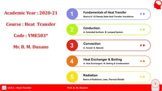
  • 1. Prof. B. M. DusaneUnit 1 : Heat Transfer 1 Fundamentals of Heat Transfer 1 2 3 4 Conduction: A: Extended Surfaces B: Lumped System Convection A. Forced B. Natural Heat Exchanger & Boiling A: Heat Exchangers B: Boiling & Condensation 5 Radiation Basics of Radiation, Laws, Thermal Shields Basics & 1-D Steady State Heat Transfer, Insulations Academic Year : 2020-21 Course : Heat Transfer Code : YME503* Mr. B. M. Dusane
  • 2. Prof. B. M. DusaneUnit 1 : Heat Transfer 2 Overview on Contents: HEAT TRANSFER Unit 1 Conduction: a) Introduction and Basic Concepts b) One dimensional steady state heat conduction without heat generation 12 Lectures Unit 2 Unit – II A. Boundary Conditions - Heat Generation B. Extended Surfaces C. and Transient Conduction 10 Lectures Unit 3 Unit – III Convection A. Forced B. Natural 8 Lectures Unit 4 Unit – A. Heat Exchangers and B. Phase Change Phenomenon- Boiling & Condensation 10 Lectures Unit 5 Unit –V Radiation 8 Lectures
  • 3. Prof. B. M. DusaneUnit 1 : Heat Transfer 3 Objectives of COURSE: HEAT TRANSFER Objectives 1 To understand the important modes of heat transfer and their applications. 2 To get acquainted with knowledge of fin selection and lumped heat capacitance. 3 To understand the mechanism of convective heat transfer 4 To learn the various heat exchangers and their applications. 5 To determine the radiative heat transfer between surfaces.
  • 4. Prof. B. M. DusaneUnit 1 : Heat Transfer 4 To differentiate different modes of heat transfer and their applications. 01 To estimate heat transfer due to convection in various applications. 03 To analyze the performance of Parallel and Counter flow heat exchangers. 04 OUTCOMES of COURSE: HEAT TRANSFER To analyse the phenomenon of conduction in Fins. 02 05 To interpret the concept of thermal radiation in various geometries.
  • 5. Prof. B. M. DusaneUnit 1 : Heat Transfer 5 Focal points Numerical Industrial Approach I. Plane wall 5 Furnace wall & Temperature distributions along length Ii Cylinder 3 Boilers- Fire Tube Boilers Many applications when pipe carries hot/cold fluids III. Sphere 2 Nuclear Power Plant Pressure vessels Design, Petroleum Tankers Iv. Variable thermal conductivity - a) ISOTROPIC material b) ANISOTROPIC material c) Metals & non metals behavoiur V. Critical radius of Insulation 3 a) Why insulation is provided?? b) Need every time?? c) In which manner insulation will economical?? Experiments 1 Thermal conductivity of insulating powder Why ‘kin ‘ should be less? How the arrangement is done with diff materials? 2 Composite Wall Why need of insertion of various material in composite wall ? Temperature Distribution.?? HOW???? Unit – I Basics & 1 –D Steady State heat Conduction , Insulation
  • 6. Prof. B. M. DusaneUnit 1 : Heat Transfer 6 Focal points Numerical Industrial Approach I. Transient Heat Conduction – Lumped System 6 a) Medicals analysis – death of human & time measurement b) Food process Industries- Potato, Chicken, Eggs, Burgers etc. c) Response of Thermocouple. II. Heat transfer through extended surface Insulated Fin 2 1. Stirrer ( Spoon, handles of machineries..etc) Infinite long 3 1.Extensions provided on the various tanks Short Fin 1 1.Automobile fins Why need of it?? How the optimization is done??? Experiments 3 PIN FIN APPARATUS (Natural Convection) How the various parameters govern on this?? 4 PIN FIN APPARATUS (Forced) Why Natural / Forced system is adapted?? Unit – II Boundary Conditions Extended Surfaces and Transient Heat Conduction
  • 7. Prof. B. M. DusaneUnit 1 : Heat Transfer 7 Focal points Numerical Industrial Approach velocity & thermal boundary layers ------------ 1. Macroscopic approach 2. Advanced Scope to study to CFD Forced convection 7 1. In high pressure boilers:- Babcock and Wilcox, Lamont , Velox, Benson Boilers etc 2. Forced Draught in Power plants etc. Natural convection 5 1. Concepts of Cooling with practical examples. 2. Solar system: Fluid flows naturally. Dimensionless numbers --------- 1. Significance & their roles. Experiments 5. Natural Convection 1. To determine ‘hConv.’ in natural convection practically and theoretically. 6. Forced Convection 1. Theoretical & Practical Approach. 2. How velocity governs on the heat flow?? 7 Thermal conductivity of metal rod 1. How the fluid flowing will be affected on K and Q Unit – III Convection
  • 8. Prof. B. M. DusaneUnit 1 : Heat Transfer 8 Focal points Numerical Industrial Approach Heat exchangers Applications & Remedies to hurdles ---------------- 1. Industrial processes- textile & sugar industries..etc 2. Scaling & methods to avoid it. LMTD Approach 4 1. How its easy to determine temp & analysis?? 2. It fails when unknown parameters will be there. NTU methods 4 1. Governing approach in industries. 2. Vastly used for analysis for their characteristics Boiling & condensations. ---------------- 1. Why bernaught flux taken into design consideration. 2. Dropwise condensation more preferable?? How?? Experiments 8 Critical Heat Flux 1. Nature of Curve & Study 9 Heat pipe 1. Advanced method in heat exchanger performance Unit –IV Heat Exchangers and Phase Change Phenomenon
  • 9. Prof. B. M. DusaneUnit 1 : Heat Transfer 9 Focal points Numerical Industrial Approach Laws of radiation 3 1. Nuclear Reactors & Shells Radiation shape factor 3 1. Why always cooking food in hemisphere pots e.g. . Bowls, Pan??? 2. Different collectors & efficiency due to Shape factor Radiation shields 2 1. Discussion on atomic power plant. 2. Thermo Flasks 3. Space Instruments etc Experiments 10 Stefan Boltzmann apparatus 1. Why difference in TH & PR values. 11 Emissivity of a Test surface 1. Black body & gray body analysis Unit –V Radiation
  • 10. Prof. B. M. DusaneUnit 1 : Heat Transfer 10 Tools Status Effects 1. Question Bank and Class Contents Ready 1. Helps to cover quality & quantitative numericals avoiding problem dictation. 2. Assignments 4 units 1. Help to traditional problem at least. 3. Practical approach In LAB during conduction. (Subjected Covid 19*) 1. Concepts & viva preparation. 4. Recall the theories ----- 1. Challenges to mini projects. 5. Expert Lecture ( By Prof N L Bhirud) Radiation-basic concepts Ready 1. Effective transformation of Radiation which will help to secure more marks 6 Reference Books 10 00 00** 10 05 1. Heat & Mass Transfer- M M Rathore 2. Heat Transfer- S P Sukhatme 3. Heat & Mass Transfer – R C Sachdeva 4. Heat Transfer – R K Rajput 5. Heat Transfer – P K Nag
  • 11. Prof. B. M. DusaneUnit 1 : Heat Transfer 11 1. Good Reference Book 2. Reading 3. Understanding 4. Doubts on time 1. Basic Laws 2. Basic terms 3. Numericals 1. Self Notes 2. Practice of problem solving • Conceptual Learning • Help to design • Score Methodology To Learn Heat Transfer
  • 12. Prof. B. M. DusaneUnit 1 : Heat Transfer 12 Heat Transfer ?? • Heat is thermal energy in transit due to a temperature difference. • Whenever there exists a temperature difference Heat Transfer MUST exist. • One dimensional steady state heat conduction: - One dimensional steady state heat conduction through a plane wall, cylindrical wall and sphere, Analogy between Heat flow and electricity, Conduction • Occurs when a temperature gradient exists through a solid or a stationary fluid (liquid or gas). • Fourier's law of conduction Conveciton • Occurs within a moving fluid, or between a solid surface and a moving fluid, when they are at different temperatures. • Newton's law of cooling Radiation • Heat transfer between two surfaces (that are not in contact), often in the absence of an intervening medium. • Stefan Boltzmann's Law
  • 13. Prof. B. M. DusaneUnit 1 : Heat Transfer 13 Heat Transfer Steady State Heat Transfer 1. T = f(x, y, z only) Unsteady State Heat Transfer 1. T = f ( x, y, z and t-time)
  • 14. Prof. B. M. DusaneUnit 1 : Heat Transfer 14 Important Laws of Heat Transfer Fourier Law of heat conduction 1- D Case : As, dx dT AkQ  dx dT A Q  dTkdx A Q  Lets consider that Q flowing through the wall. Lets take integration and apply limits   2 10 T T L dTkQ Where k = Thermal conductivity of material in W/m.K L – Thickness of Wall A – C/S Area normal to heat flow
  • 15. Prof. B. M. DusaneUnit 1 : Heat Transfer 15 )( 12 TTkL A Q  We will get L TT dx dT )( 21   )( 21 TT L Ak Q    CondR T Q )(  )( 21 TT L Ak Q   Summary )( Ak L T Q   
  • 16. Prof. B. M. DusaneUnit 1 : Heat Transfer 16 Newton’s Law of Cooling : Convection )(  TT A Q s )(.  TTAhQ ss s s Ah TT Q . 1 )(   ConvR T Q )(  Stefan Boltzmann's Law of radiation : 4 )(TAQ S 4 TAQ S   Black Body Gray Body
  • 17. Prof. B. M. DusaneUnit 1 : Heat Transfer 17 To Solve basic Numericals in Heat Transfer in Unit 1 Write your comment with answers. Apply basic laws of Conduction/Convection / Radiation and make suitable assumptions. Draw Block diagram first and think mode of heat transfer involved in the given numerical. Read Problem twice and try to write given data correctly.
  • 18. Prof. B. M. DusaneUnit 1 : Heat Transfer 18 Example 1. Determine the heat flow across a plane wall of 10 cm thickness with a constant thermal conductivity of 8.5 W/mK when the surface temperatures are steady at 100°C and 30°C. The wall area is 3m2. Also find the temperature gradient in the flow direction. Given Data : T1 = 100°C, T2 = 30°C, L = 10 cm = 0.1 m, k = 8.5 W/mK, A = 3 m2. conductionR T Q  1 kA L T Q   35.8 1.0 )30100(   Q WQ 17850 T 1 T2 Q L According to Fourier's Law: dX dT kAQ  dX dT  35.817850 mC dX dT /700
  • 19. Prof. B. M. DusaneUnit 1 : Heat Transfer 19 2. A person sits in a room with surrounding air at 26°C and convection coefficient over the body surface is 6 W/m2K. The walls in the room are at 5°C as the outside temperature is below freezing. If the body temperature is 37°C, determine the heat losses by convection and radiation. Assume F = 1.0 for radiation. Consider a surface area of 0.6 m2. Given Data : = 6 𝑊/𝑚2 𝑘 𝑇 𝐵𝑜𝑑𝑦 = 37℃ 𝑇 ∞ = 26℃ 𝑇 𝑊𝑎𝑙𝑙 = 5℃ 𝐴 𝑠 = 0.6 𝑚2 According to Newton’s Law of Cooling : )(  TTAhQ SSConv WQ Q conv Conv 6.39 )2637(6.06   According to Stefan Boltzmann’s Law of Radiation : )( 44 WallSSRad TTAQ  WQRad 99.110 WQTotal 59.150 Convection heat loss, we already calculated: WQconv 60.39 Now if summer condition is there then temperature of wall is also becomes 26 °C radiation loss is given by: )( 44 WallSSRad TTAQ   WQrad 28.42 WQTotal 88.81
  • 20. Prof. B. M. DusaneUnit 1 : Heat Transfer 20 3. A horizontal plate (K=30W/m. K) 600mm X 900mm X 30mm is mentioned at 3000 C. The air at 300C flows over the plate. If the convection co-efficient of air over the plate is 22 w/m2. K & 250 W heat is lost from the plate by radiation, calculate the bottom surface temperature of the plate. Given data : 𝐿 × 𝑏 × ℎ = 0.6 𝑚 × 0.9 𝑚 × 0.03𝑚 𝑇𝑠 = 300°𝐶, 𝑇 ∞ = 30°𝐶 𝑂𝑢𝑡𝑠𝑖𝑑𝑒 𝐶𝑜𝑛𝑣𝑒𝑐𝑡𝑖𝑣𝑒 ℎ𝑒𝑎𝑡 𝑡𝑟𝑎𝑛𝑠. 𝑐𝑜𝑒𝑓𝑓. ℎ𝑜 = 22 𝑊/𝑚2 𝑘 𝑇ℎ𝑒𝑟𝑚𝑎𝑙 𝐶𝑜𝑛𝑑𝑢𝑐𝑡𝑖𝑣𝑖𝑡𝑦 𝑜𝑓 𝑚𝑎𝑡𝑒𝑟𝑖𝑎𝑙 𝑘 = 30 𝑊/𝑚𝐾 Thickness of Plate 𝐿 = 0.03𝑚 𝑄 𝑅𝑎𝑑 = 250 𝑊. 𝑇 ∞ = 30°𝐶 ℎ𝑜 = 22 𝑊/𝑚2 𝑘 0.6m 0.03m Q cond. 𝑄 𝑅𝑎𝑑 𝑄 𝑐𝑜𝑛𝑣 Assumptions: 1. 1-D Steady State heat conduction without heat generation. 2. Thermal properties remains constant.
  • 21. Prof. B. M. DusaneUnit 1 : Heat Transfer 21 𝑇 ∞ = 30°𝐶 ℎ𝑜 = 22 𝑊/𝑚2 𝑘 0.6 m 0. 03 m Q cond. 𝑄 𝑅𝑎𝑑 𝑄 𝑐𝑜𝑛𝑣 Analysis: Area of surface of the plate : 𝐴𝑠 = 0.6 m x 0.9 m 𝐴𝑠 = 0.54 m2 According to Fourier’s Law of conduction: )( Sbottom c Cond TT L Ak Q    )300( 03.0 54.030    bottomCond TQ …..Eq (A) By putting all values in the above equation : By Energy balance Equation we can write: Rate of Heat Conduction = [ Rate of Heat Convection + rate of Heat Radiation ] )( Sbottom c Cond TT L Ak Q    )300( 03.0 54.030    bottomCond TQ )( Sbottom c Cond TT L Ak Q    )300( 03.0 54.030    bottomCond TQ
  • 22. Prof. B. M. DusaneUnit 1 : Heat Transfer 22 5. An uninsulated steam pipe passes through a room in which the air and walls are at 25°C.The outside diameter of the pipe is 70 mm, and its surface temperature and emissivity are 200C and 0.8, respectively. What are the surface emissive power and irradiation? If the coefficient associated with free convection heat transfer from the surface to the air is 15 W/m2 K, what is the rate of heat loss from the surface per unit length of pipe? (QB- 5 – Short) 4. A refrigerator stand in a room where the temp of air is 21° C and surface temp at outside of the cover of system is 16 °C. The sides are 30 mm thick and thermal conductivity of material 0.1 w/mk. Outside heat transfer coefficient is 10 w/m2k. Assuming that heat flow is one dimensional conduction through the sides , calculate heat flow rate and inside temp of refrigerator system.
  • 23. Prof. B. M. DusaneUnit 1 : Heat Transfer 23 6. An immersion water heater of a surface area 0.1 m2 and rating of 1 KW is design to operate fully submerged in water. Estimate the surface temp of heater when water temp is at 40 °C and heat transfer coefficient 300 w/m2k. IF this heater by mistake use in air at 40 °C. with h of 9 w/m2k what will be surface tempt?
  • 24. Prof. B. M. DusaneUnit 1 : Heat Transfer 24 • Material Properties: The property specific heat Cp as a measure of a material’s ability to store thermal energy. For example, Cp 4.18 kJ/kg . • Defination: The thermal conductivity k is a measure of a material’s ability to conduct heat. • Thermal conductivity of a material can be defined as the rate of heat transfer through a unit thickness of the material per unit area per unit temperature difference. • What it indicates? – High value ? And Low Value of Thermal Conductivity. • Why to study ? Selection of Material, Applications. • Types of Material : • A) ISOTROPIC : Thermal Conductivity does not vary with change indirection. • B) ANISOTROPIC : Thermal conductivity depend upon the direction of flow
  • 25. Prof. B. M. DusaneUnit 1 : Heat Transfer 25 • Thermal conductivity of a material is defined as the rate of heat transfer through a unit thickness of the material per unit area per unit temperature difference. • The thermal conductivity of a material is a measure of how fast heat will flow in that material. • A large value for thermal conductivity indicates that the material is a good heat conductor, • A low value indicates that the material is a poor heat conductor or insulator. THERMAL CONDUCTIVITY
  • 26. Prof. B. M. DusaneUnit 1 : Heat Transfer 26 • Figure shows the range of thermal conductivity for various states of matter at normal temperature and pressure. Reference : Heat and Mass Transfer: Fundamentals & Applications Yunus A. Cengel, Afshin J. Ghajar, McGraw-Hill, 2011
  • 27. Prof. B. M. DusaneUnit 1 : Heat Transfer 27 A solid may comprised free electrons and of atoms bound in a periodic arrangement called the lattice. Accordingly, transport of thermal energy is due to two effects: the migration of free electrons and lattice vibrational waves. These effects are additive, such that the thermal conductivity k is the sum of the electronic component ke and the lattice component kl k = ke + kl where, ke is inversely proportional to the electrical resistivity ρe . For pure metals, which are of low ρe, ke is much larger than kl . For alloys, which are of substantially larger ρe, the contribution of kl to k is no longer negligible. For non-metallic solids, k is determined primarily by kl , which depends on the frequency of interactions between the atoms of the lattice.
  • 28. Prof. B. M. DusaneUnit 1 : Heat Transfer 28 Reference : Heat and Mass Transfer: Fundamentals & Applications Yunus A. Cengel, Afshin J. Ghajar, McGraw-Hill, 2011 • Thermal insulation systems are comprised of low thermal conductivity materials combined to achieve an even lower system thermal conductivity. • In fiber-, powder-, flake-type insulations, the solid material is finely dispersed throughout an air space to achieve effective thermal conductivity. Effective thermal conductivity of such systems depends on 1. the thermal conductivity 2. surface radiative properties of the solid material, 3. the nature and volumetric fraction of the air or void space. 4. A special parameter of the system is its bulk density (solid mass/total volume), which depends strongly on the manner in which the solid material is interconnected INSULATION SYSTEMS
  • 29. Prof. B. M. DusaneUnit 1 : Heat Transfer 29 • Liquid : Thermal Conductivity decreases with increase in Temp. • Exceptional case : Water & Glycerine. • In Liquid K is function of Molecular weight and independent of Pressure. • Solid (Metal) : two effects: the lattice vibrational waves induced by the vibrational motions & Free Electrons. • Effect of Temperature : As T ↑ , Thermal conductivity decreases in Metal • Exceptional case : Mercury • Solid ( Non-metal) : Absence of free electrons. • No of collisions increase with increase in temperature. • As T ↑ Then , Thermal conductivity increases in Non- Metal Prof. B. M. Dusane , Dept. of Mechanical Engineering, S.O.E.T., Sandip University Nashik
  • 30. Prof. B. M. DusaneUnit 1 : Heat Transfer 30 • Gases : Thermal Conductivity increases with increase in temperature. • Transfer of energy due to continuous random motion of molecules. • K is function of square root of absolute temperature. • Affected by humidity and pressure. • Determination of Thermal Conductivity (k): By using Fourier's law of heat conduction we can calculate the value of k practically. Q= W L T 1 T 2 Heater Coil
  • 31. Prof. B. M. DusaneUnit 1 : Heat Transfer 31 Reference : Heat and Mass Transfer: Fundamentals & Applications Yunus A. Cengel, Afshin J. Ghajar, McGraw-Hill, 2011
  • 32. Prof. B. M. DusaneUnit 1 : Heat Transfer 32
  • 33. Prof. B. M. DusaneUnit 1 : Heat Transfer 33 • Material property that appears in the transient heat conduction analysis is the thermal diffusivity, which represents how fast heat diffuses through a material. • The thermal conductivity k represents how well a material conducts heat, and the heat capacity Cp represents how much energy a material stores per unit volume. • Therefore, the thermal diffusivity of a material can be viewed as the ratio of the heat conducted through the material to the heat stored per unit volume. capacityHeat ductivityThermalCon   PC k    NOTE: 1. Materials of large α will respond quickly to changes in their thermal environment 2. Materials of small α will respond more sluggishly to reach new equilibrium condition.
  • 34. Prof. B. M. DusaneUnit 1 : Heat Transfer 34 Thermal Resistance 1. There exists an analogy between the diffusion of heat and electrical charge. 2. Thermal resistance may be associated with the conduction of heat in the same fashion as an electrical resistance is associated with the conduction of electricity. 3. Defining resistance as the ratio of a driving potential to the corresponding transfer rate 4. it follows from Equation - that the thermal resistance for conduction is (a) Similarly, for electrical conduction, Ohm's law provides an electrical resistance of the form (b)   cond 1 2s, s, t , x T T L R q kA     1 2s, s, e E E L R l A   
  • 35. Prof. B. M. DusaneUnit 1 : Heat Transfer 35 Therefore, • the rate of heat transfer through a plane wall corresponds to the electric current • the thermal resistance corresponds to electrical resistance and • the temperature difference corresponds to voltage difference across the plane wall. (Figure.) Figure : Analogy Between Thermal And Electrical Resistance Concepts
  • 36. Prof. B. M. DusaneUnit 1 : Heat Transfer 36 Conduction resistance of the wall: Thermal resistance of the wall against heat conduction. Thermal resistance of a medium depends on the geometry and the thermal properties of the medium. Electrical resistance Fig :Analogy between thermal and electrical resistance concepts. rate of heat transfer (Q) electric current (I) thermal resistance R  electrical resistance R temperature difference ∆T  voltage difference ∆V Reference : Heat and Mass Transfer: Fundamentals & Applications Yunus A. Cengel, Afshin J. Ghajar, McGraw-Hill, 2011 ELECTRICAL ANALOGY c e A L R   
  • 37. Prof. B. M. DusaneUnit 1 : Heat Transfer 37 ELECTRICAL ANALOGY CondR T Q )(  )( 21 TT L Ak Q    Summary )( Ak L T Q    Convection Case : R convConduction Case : R cond )( 21 TTAhQ s  TAhQ s  conv s R T Ah T Q      1
  • 38. Prof. B. M. DusaneUnit 1 : Heat Transfer 38 The thermal resistance network for heat transfer through a plane wall subjected to convection on both sides, and the electrical analogy.
  • 39. Prof. B. M. DusaneUnit 1 : Heat Transfer 39 Multilayer Plane Walls The thermal resistance network for heat transfer through a two-layer plane wall subjected to convection on both sides. Reference : Heat and Mass Transfer: Fundamentals & Applications Yunus A. Cengel, Afshin J. Ghajar, McGraw-Hill, 2011
  • 40. Prof. B. M. DusaneUnit 1 : Heat Transfer 40 x=0 x=L Too 2, Too 1, Too 2, Too 1, Ts,1 Ts,2 h2h1 Hot Fluid Cold Fluid q x Too 1, Ts,2 Too 2,Ts,1 1 h1 A L k A 1 h2A x=0 x=L Too 2, Too 1, Too 2, Too 1, Ts,1 Ts,2 h2h1 Hot Fluid Cold Fluid LBLA LC q x Too 1, Ts,4 Too 4,Ts,1 T2 T3 1 h1 A L kA A A L kB A B L kC A C 1 h4A  1 4 1 4 1 1 , , x CA B A B C T T q LL L h A k A k A k A h A                                        1 1 1 2 2 2 1 2 1 1 , s, s, s, s, , x T T T T T T q L h A kA h A       
  • 41. Prof. B. M. DusaneUnit 1 : Heat Transfer 41 HEAT CONDUCTION IN CYLINDERS AND SPHERES A long cylindrical pipe (or spherical shell) with specified inner and outer surface temperatures T1 and T2. Reference : Heat and Mass Transfer: Fundamentals & Applications Yunus A. Cengel, Afshin J. Ghajar, McGraw-Hill, 2011
  • 42. Prof. B. M. DusaneUnit 1 : Heat Transfer 42 A spherical shell with specified inner and outer surface temperatures T1 and T2. Reference : Heat and Mass Transfer: Fundamentals & Applications Yunus A. Cengel, Afshin J. Ghajar, McGraw-Hill, 2011
  • 43. Prof. B. M. DusaneUnit 1 : Heat Transfer 43 1-D STEADY STATE HEAT Conduction without heat generation Numericals and Applications: A. Rectangular System: • Application of Walls • Need to estimate thickness or width or suitable material for a given application. • Need to find Thermal Conductivity & Select the specific material B. Cylindrical System • Steam Pipes, heat exchanger's tube, Coils • Wires, • Pressure Vessels C. Sphere: • Nuclear Reactor, Combustion chambers Resistance of different Entities : 1. Rectangular /Square (Wall) AK L RWall   2. Cylindrical System : LK r r RCylinder         2 ln 1 2 3. Spherical System : 21 )12 4 ( rKr rr RSphere   
  • 44. Prof. B. M. DusaneUnit 1 : Heat Transfer 44 Objectives To derive the three dimensional heat diffusion equation in Cartesian co-ordinates from first principle and various boundary and initial conditions are stated. THE HEAT DIFFUSION EQUATION A major objective in a conduction analysis is to determine the temperature field in a medium resulting from conditions imposed on its boundaries. We now consider the manner in which the temperature distribution can be determined. We define a differential control volume, identify the relevant energy transfer processes, and introduce the appropriate rate equations.  The result is a differential equation whose solution, for prescribed boundary conditions, provides the temperature distribution in the medium.
  • 45. Prof. B. M. DusaneUnit 1 : Heat Transfer 45 To determine the differential equation whose solution, for prescribed boundary conditions, provides the temperature distribution in the medium. Consider, • a homogenous medium • with no bulk motion and • temperature distribution T(x,y,z) Consider a infinitesimally small control volume dx.dy.dz , as shown in Figure.2 Figure 2. Differential Control Volume For Conduction Analysis In Cartesian Coordinates
  • 46. Prof. B. M. DusaneUnit 1 : Heat Transfer 46 The conduction heat rates perpendicular to each of the control surfaces at the x, y and z coordinate locations are indicated by the terms qx, qy , and qz , respectively. The conduction heat rates at the opposite surfaces can then be expressed as a Taylor series expansion where, neglecting higher order terms, (2.9a) (2.9b) (2.9c) Equation 2.9a simply states that the x component of the heat transfer rate at x+dx is equal to the value of this component at x plus the amount by which it changes with respect x times dx. stE qdxdydz Within the medium there may also be an energy source term. This term is represented as (2.10)           dx x Q QQ x xdxx           dy y Q QQ y ydyy           dz z Q QQ z zdzz
  • 47. where is the rate at which energy is generated per unit volume of the medium (W/m3). There may occur changes in the amount of the internal thermal energy stored by the material in the control volume. The energy storage term may be expressed as (2.11) where is the time rate of change of the thermal (sensible) energy of the medium per unit volume. The general form of the conservation of energy is (2.12) (2.13) q st p T E C dxdydz t     p T C t    in g out stE E E E   in x y zE q q q  
  • 48. (2.14) substituting Equations 2.9, 2.13 and 2.14 in Equation 2.12, we obtain (2.15) substituting from Equation 2.9, it follows that (2.16) The conduction heat rates is evaluated from Fourier's law (2.17a) (2.17b) (2.17c) out x dx y dy z dzE q q q     x y z x dx y dy z dz p T q q q q dxdy dz q q q C dxdy dz t             yx z p qq q T dx dy dz qdxdy dz C dxdy dz x y z t              x T q k dydz x     y T q k dxdz y     z T q k dxdy z    
  • 49. where each heat flux component has been multiplied by an appropriate control surface area to obtain the heat transfer rate. Substituting Equations 2.17 into 2.16 and dividing out the dimensions of the control volume ( dx dy dz) , we obtain (2.18) Equation 2.18 is the general form of the heat diffusion equation in Cartesian coordinates. From the solution of this heat equation, we can obtain the temperature distribution T(x,y,z) as a function of time. If the thermal conductivity is a constant, the heat equation is (2.19) Where is the thermal diffusivity. Under steady-state conditions , there can be no change in the amount of energy storage; hence equation 2.18 reduces to p T T T T k k k q C x x y y z z t                               2 2 2 2 2 2 1T T T q T k tx y z             p k C   
  • 50. (2.20) If the heat transfer is one dimensional (e.g., in the x direction) and there is no energy generation , Equation 2.20 reduces to (2.20a) The most important implication of this result is that under steady state, one dimensional conditions with no energy generation, the heat flux is a constant in the direction of heat transfer 0 T T T k k k q x x y y z z                            0 d dT k dx dx      
  • 51. Prof. B. M. DusaneUnit 1 : Heat Transfer 51 Application of Wall Design Que. 1. An exterior wall of house may be approximated by 0.1 m Layer of common brick (k= 0.7 W/mK) followed by a 0.04 m layer of gypsum plaster having k = 0.48 W/mK. What thickness of loosely packed rock wool insulation (k= 0.065 W/mK) should be added to reduce heat loss through the wall by 80%? Given Data : Thickness of common Brick : 𝐿 𝐴 = 0.1 m Thickness of Gypsum : 𝐿 𝐵 = 0.04 m Thickness of Rock-wool (say) : 𝐿 𝐶 = X in m. Thermal Conductivity of common Brick : 𝐾 𝐴 = 0.7 W/mK Thermal Conductivity of gypsum :𝐾 𝐵 = 0.48 W/mK Thermal Conductivity of Rock-wool : 𝐾 𝐶 = 0.065 W/mK Case 1 : Q With Common Brick & Gypsum Case 2: Q with all 3 types of material mentioned above Assumptions: 1. 1-D Steady State heat conduction without heat generation. 2. Thermal properties remains constant. 3. Area is considered as 1 sq. metre. (If necessary) 4. Contact resistance is neglected Case 1 : Q with Brick and gypsum: WallR T Q  1 BA RR T Q   1 BA RR T Q   1 48.0 04.0 7.0 1.01    TA Q )(4210.41 TAQ  On Solving, we get ……… (A)
  • 52. Prof. B. M. DusaneUnit 1 : Heat Transfer 52 Case 2: When Rockwool is added and will have 3 materials R T Q   2 CA RRR T Q    B 2 C C B B A A K L K L K L TA Q   2 065.048.0 04.0 7.0 1.02 Lc TA Q    065.0 22619.0 2 CL TA Q    But as per given condition , heat loss should be reduced by 80% so we can write : ).......(2.0 %20 12 12 BQQ QQ   )(4210.4 065.048.0 04.0 7.0 1.0 TA Lc TA    By putting values from equation (A) & (B) On solving this equation, we will get value of Lc mmmLC 8.580588.0  Thus , the thickness of Rockwool should be 58.8 mm.
  • 53. Prof. B. M. DusaneUnit 1 : Heat Transfer 53 Que 2: An ice box (20 cm × 20 cm × 10 cm height) is filled with 3 Kg of ice at 0°C. The bottom and all vertical sides are well insulated. The top cover of the box is 1 cm thick and is made up of a with K = 0.33 W/mK. The cover is exposed to ambient air at 25°C with h = 10 W/m2 K. The heat transfer coefficient between inner surface of cover and air inside the box is 8 W/m2 K. Calculate the time required for the ice in the box to melt completely. Take latent heat of fusion of ice = 330 kJ/kg. Given data : 𝐿 × 𝑏 × ℎ = 0.2 𝑚 × 0.2 𝑚 × 0.1𝑚 𝑚 𝑖𝑐𝑒 = 3 𝑘𝑔, 𝑇0 = 0°𝐶, 𝑇 ∞ = 25°𝐶 𝑂𝑢𝑡𝑠𝑖𝑑𝑒 𝐶𝑜𝑛𝑣𝑒𝑐𝑡𝑖𝑣𝑒 ℎ𝑒𝑎𝑡 𝑡𝑟𝑎𝑛𝑠. 𝑐𝑜𝑒𝑓𝑓. ℎ𝑜 = 10 𝑊/𝑚2 𝑘 𝐼𝑛𝑠𝑖𝑑𝑒 𝐶𝑜𝑛𝑣𝑒𝑐𝑡𝑖𝑣𝑒 ℎ𝑒𝑎𝑡 𝑡𝑟𝑎𝑛𝑠. 𝑐𝑜𝑒𝑓𝑓. ℎ𝑖 = 𝑊/𝑚2 𝑘 𝑇ℎ𝑒𝑟𝑚𝑎𝑙 𝐶𝑜𝑛𝑑𝑢𝑐𝑡𝑖𝑣𝑖𝑡𝑦 𝑜𝑓 𝑚𝑎𝑡𝑒𝑟𝑖𝑎𝑙 (𝑘) = 0.33 𝑊/𝑚𝐾 𝐿𝑎𝑡𝑒𝑛𝑡 ℎ𝑒𝑎𝑡 𝑜𝑓 𝑓𝑢𝑠𝑖𝑜𝑛 𝑜𝑓 𝑖𝑐𝑒 ℎ 𝑓𝑔 = 330 𝐾𝐽/𝐾𝑔 Assumptions: 1. 1-D Steady State heat conduction without heat generation. 2. Thermal properties remains constant. 3. Material is isotropic ie. K remains constant in all directions. 4. Contact resistance is neglected Thickness of Cover ICE Application of Refrigerator-Cover
  • 54. Prof. B. M. DusaneUnit 1 : Heat Transfer 54 As surface area of cover = 0.2 x 0.2 m = 0.04 m2 𝑇𝑜𝑡𝑎𝑙 𝑟𝑒𝑠𝑖𝑠𝑡𝑎𝑛𝑐𝑒 𝑖𝑛 𝑡ℎ𝑒 𝑠𝑦𝑠𝑡𝑒𝑚 = 3 Σ 𝑅 = 𝑅 𝐶𝑜𝑛𝑣1 + 𝑅 𝐶𝑜𝑛𝑑 + 𝑅 𝑐𝑜𝑛𝑣2 AhAK L Ah R io       11 𝐻𝑒𝑎𝑡 𝑇𝑟𝑎𝑛𝑠𝑓𝑒𝑟 𝑟𝑎𝑡𝑒 , R TT Q io    WQ 917.3 3826.6 )025(    AhAK L Ah R io       11        8 1 33.0 01.0 10 1 04.0 1 R WKR /3826.6 Now energy required to melt ice of 3 kg : 3303 fgiceMelt hmQ KJQMelt 990 Time to melt ice can be calculated by : Q Q t Melt  hourst 207.70sec1074.252 3  917.3 990 t dayst 3
  • 55. Prof. B. M. DusaneUnit 1 : Heat Transfer 55 Que.3. A circular plate heater (diameter 20 cm) is inserted between two circular plates (diameter 20 cm), slab A is 3 cm thick (k = 55 W/mK) and slab B is 1.5 cm thick (k = 0.18 W/mK). The outside heat transfer coefficient on sides of A and B are 200 and 65 W/m2 K respectively. The temperature of surrounding air is 30°C. If the rating of heater is 2kW, find : A) maximum temp. in the system. B)Outer surface temp. of two sides. C) Draw equivalent electrical circuit of the system. Diameter of heater : d = 20 cm = 0.2 m 𝐴𝑟𝑒𝑎 𝑜𝑓 ℎ𝑒𝑎𝑡𝑒𝑟 = 𝜋 4 × 𝑑 2 = 0.0314 m2 𝑇ℎ𝑖𝑐𝑘𝑛𝑒𝑠𝑠 𝑜𝑓 𝑠𝑙𝑎𝑏 𝐴 = 3𝑐𝑚 = 0.03𝑚 𝑎𝑛𝑑 𝐾𝐴 = 55𝑊/𝑚𝐾 Thickness of slab B =1.5 cm = 0.015m and KB = 0.18W/mK 𝐶𝑜𝑛𝑣𝑒𝑐𝑡𝑖𝑣𝑒 ℎ𝑒𝑎𝑡 𝑡𝑟𝑎𝑛𝑠. 𝑐𝑜𝑒𝑓𝑓. 𝐴 𝑠𝑖𝑑𝑒 ℎ𝐴 = 200 𝑊/𝑚2 𝑘 𝐶𝑜𝑛𝑣𝑒𝑐𝑡𝑖𝑣𝑒 ℎ𝑒𝑎𝑡 𝑡𝑟𝑎𝑛𝑠. 𝑐𝑜𝑒𝑓𝑓. 𝐵 𝑠𝑖𝑑𝑒 ℎ𝐵 = 65 𝑊/𝑚2 𝑘 Rating of Heater (Q) = 2kW 𝑆𝑢𝑟𝑟𝑜𝑢𝑛𝑑𝑖𝑛𝑔 𝑇𝑒𝑚𝑝 ∶ 𝑇∞ = 30°𝐶 Assumptions: 1. 1-D Steady State heat conduction without heat generation. 2. Thermal properties remains constant. 3. Material is isotropic ie. K remains constant in all directions. 4. Contact resistance is neglected 30°C30°C LA LB Application of Heater Design
  • 56. Prof. B. M. DusaneUnit 1 : Heat Transfer 56 Let us consider that , Tm is maximum temperature in the system. Under steady state heat flow condition: AA A m AA A m convA m A hK L TTA AhAK L TT RR TT Q 1 )( 1 )()( 1             SideBSideA BATotal R T R T QQQ        BB B m BB B m convB m B hK L TTA AhAK L TT RR TT Q 1 )( 1 )()( 2             So we can write equation for Total heat: 65 1 18.0 015.0 03141.0)30( 200 1 55 03.0 03141.0)30( 2000       mm TT On solving above equation, we will get value of Tm CTm  32.364 To find outer surface temperature of slab: AconvAConductionA QQQ   )( ( )    TTAh L TTAK Q AA A AmA A )( )32.364(   TTh L TK A A AA Electrical Analogy : Tmax T-Surrounding RBRC1 Rc2RA
  • 57. Prof. B. M. DusaneUnit 1 : Heat Transfer 57 )30(200 03.0 )32.364(55   A A T T C331.44TA  Similarly we can find TB )( )32.364(   TTh L TK B B AB )30(65 015.0 )32.364(18.0   B A T T C82.1TB  Thus , Maximum temperature in the system is 364.32°C and surface temperatures of the heater are 331.44°C and 82.1°C. Unit of quantities plays very important role and make necessary assumptions for given numerical. Draw Block diagram first and then Electrical Circuit diagram if resistances more than 2. Read Problem twice and try to write given data correctly. Boundary of system and henceforth decision making about number of resistances. Points To Be Remembered:
  • 58. Prof. B. M. DusaneUnit 1 : Heat Transfer 58 Application- Steam Pipe System Que. 4. A steam pipe is covered with two layers of insulations, first layer being 3 cm thick and second 5 cm. The pipe is made of steel (k= 58 W/mK) having ID of 160 mm and OD of 170 mm. The inside and outside film coefficients are 30 and 5.8 W/m2 K,respectively. Calculate the heat lost per metre of pipe, if the steam temperature is 300 °C and air temperature is 50 °C. The thermal conductivity of two insulating materials are 0.17 and 0.093 W/mK respectively. Given Data: Entity – Cylinder: mmmmmmmthicknessrr mmmmmmmthicknessrr mmmd mmmd 165.016550115 115.01153085 17.0170 16.0160 34 23 2 1     CT CT o i   50 300 KmWh KmWh o i 2 2 /8.5 /30   Q mKWk mKWk mKWk /093.0 /17.0 /58 3 2 1    Assumptions: 1. 1-D Steady State heat conduction without heat generation in radial direction only. 2. Thermal properties remains constant. 3. Material is isotropic ie. K remains constant in all directions. 4. Contact resistance is neglected 5. Length of cylinder is assumed as 1 m.
  • 59. Prof. B. M. DusaneUnit 1 : Heat Transfer 59 R TT Q oi    ToTi RConv2 .. .. .. R2 .. Rconv1 .. R1 .. R3 .. But Ʃ R can be estimated as: WK LhRAh R ii conv /0663.0 2 11 1 1      WK Lk r r R /10663.1 2 )ln( 4 1 1 2 1     WK Lk r r R /283.0 2 )ln( 2 2 3 2    WK LhRAh R io conv /166.0 2 11 4 2      WK Lk r r R /618.0 2 )ln( 3 3 4 3    23211   convconv RRRRRR WKR /134.1 Now, heat flow rate through the composite pipe: mWQ R TT Q oi /5.220 134.1 )50300(      
  • 60. Prof. B. M. DusaneUnit 1 : Heat Transfer 60 Que.5. A spherical thin walled metallic container is used to store liquid nitrogen at 77 K. The container has a diameter of 0.5 m and is covered with an evacuated reflective insulation system composed of silica powder (k = 0.0017 W/mK). The insulation is 25 mm thick and its outer surface is exposed to ambient air at 300 K. The convective coefficient is known to be 20 W/m2 K. The latent heat of vapourisation and density of liquid nitrogen are 2 x10⁵ J/Kg and 804 kg/m3 respectively. 1. What is the rate of heat transfer to the liquid nitrogen? 2. What is the rate of liquid boil off? Nitrogen at 77K Q KT KmWho 300 /20 2    Rsp R conv KT 77 KT 300Q
  • 61. Prof. B. M. DusaneUnit 1 : Heat Transfer 61 Given Data: 𝐷𝑖𝑎𝑚𝑒𝑡𝑒𝑟 𝐷 = 0.5 𝑚 𝑠𝑜, 𝑟1 = 0.25𝑚 𝑂𝑢𝑡𝑒𝑟 𝑟𝑎𝑑𝑖𝑢𝑠 𝑟2 = 𝑟1 + 25 𝑚𝑚 = 0.275 𝑚 ℎ 𝑓𝑔 = 2 × 10 5 𝐽/𝐾𝑔 𝑘 = 0.0017 𝑊 𝑚𝐾 ℎ 𝑂 = 20 𝑤 𝑚2 𝑘 𝑇∞ = 300𝐾 and 𝑇𝑖 = 77 𝐾 𝜌 = 804 𝑘𝑔/𝑚3 Assumptions: 1. 1-D Steady State heat conduction without heat generation in radial direction only. 2. Thermal properties remains constant. 3. Contact resistance is neglected 4. No radiation heat loss. W R T Q 06.13 074.17 )77300(       Solution : convsphere RRR  ohrrkr rr R 2 221 12 4 1 4 )(      WKR /074.17 Heat loss to nitrogen will also cause evaporation: fghmQ  sec/1053.6 102 06.13 5 5 kg h Q m fg     hrkgkgm /235.0sec/1053.6 5   On Volumetric basis: ./7/10923.2 804 235.0 34 daylithrm m V   
  • 62. Prof. B. M. DusaneUnit 1 : Heat Transfer 62 We know that by adding more insulation to a wall always decreases heat transfer. This is expected, since the heat transfer area A is constant, and adding insulation will always increase the thermal resistance of the wall without affecting the convection resistance. However, adding insulation to a cylindrical piece or a spherical shell, is a different matter. The additional insulation increases the conduction resistance of the insulation layer but it also decreases the convection resistance of the surface because of the increase in the outer surface area for convection. Therefore, the heat transfer from the pipe may increase or decrease, depending on which effect dominates. THE CRITICAL RADIUS OF INSULATION
  • 63. Prof. B. M. DusaneUnit 1 : Heat Transfer 63 Consider a cylindrical pipe (Figure. ), where, r1 -- outer radius T1 -- constant outer surface temperature k -- thermal conductivity of the insulation r2 -- outer radius - temperature of surrounding medium h - convection heat transfer coefficient Figure :Insulated Cylindrical Pipe
  • 64. Prof. B. M. DusaneUnit 1 : Heat Transfer 64 r r 1 2 k h Qmax . . Qbare Q . 0 r =k/hcr r r1 2 Figure : Variation Of Heat Transfer Rate With Radius The critical radius of insulation for a cylindrical body:
  • 65. Prof. B. M. DusaneUnit 1 : Heat Transfer 65 The rate of heat transfer from the insulated pipe to the surrounding air can be expressed as (Eqn. A) (A) The variation of heat transfer rate with the outer radius of insulation r2 is plotted in Figure . The value of r2 at which heat transfer rate reaches maximum is determined from the requirement that (zero slope). Performing the differentiation and solving for r2 gives us the critical radius of insulation for a cylindrical body to be (B) NOTE: The rate of heat transfer from the cylinder increases with the addition of insulation for r2< rcr, reaches a maximum when r2= rcr, and starts to decrease for r2> rcr. Thus, insulating the pipe may actually increase the rate of heat transfer from the pipe instead of decreasing it when r2< rcr .     1 2 1 2 1 2 2 r T T q r ln r Lk h r L           cr ,cylinder k r h  rdq dr
  • 66. Prof. B. M. DusaneUnit 1 : Heat Transfer 66 1. S.P. Sukhatme, A Textbook on Heat Transfer, Universities Press. 2. P.K. Nag, Heat & Mass Transfer, McGraw Hill Education Private Limited. 3. M. M. Rathore, Engineering Heat and Mass Transfer, 2nd Edition, University Press Publication. 4. R K Rajput, Heat Transfer , S Chand Publication. Text Books : 1. F.P. Incropera, D.P. Dewitt, Fundamentals of Heat and Mass Transfer, John Wiley. 2. Y. A. Cengel and A.J. Ghajar, Heat and Mass Transfer – Fundamentals and Applications, Tata McGraw Hill Education Private Limited. Reference Books: