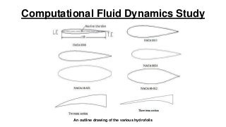
Aerofoils
• A twodimensional cross section of a wing(such as the wing of an airplane) is called a foil.
• Aerofoils generate lift, which balance the aircraft.
• A hydrofoil is a wing that ‘flies’ in water.
• Hydrofoil is also used to refer the boats supported on water wings.
• The first practical theory for predicting the aerodynamics properties of finite wing was developed by
PRANDTL and his colleagues at Gottingen, Germany during the period 1911-1918.
Problem Definition
• Studyof conventional sections- Various NACA foils were studied and Lift and Drag coefficients
for various angles of attack and Reynolds number were obtained.
• These values compared with experimental values.
• Study of non-conventional sections-some of the non-conventional foils (Two-term and Threeterm sections) were studied.
• However computations were made before the occurrence of cavitation, hence the two phase
flow was not consider in these case.
• Study of the ground effect on foil-NACA0024 foil is studied by placing the foil at different heights
from ground. Effect of presence of a wall, parallel to the chord of the foil is studied.
5.
Methods Of Prediction
Predictionof heat transfer and fluid flow process can be obtained by two main methods:
• Experimental investigation
• Theoretical calculation
6.
Experimental investigation
• Themost reliable information about the physical process is often
given by actual measurement.
• It involves full-scale equipment, which can be used to predict how
identical copies of the equipment would perform under the same
conditions.
7.
Advantages and Disadvantages
ADVANTAGES:
•It has the capability of producing the most realistic answers for many problems.
• It can be used to predict how identical copies of the equipment would perform
under the same conditions.
DIS-ADVANTAGES:
• More equipment required
• Scaling problems.
• Tunnel corrections
• Measurement difficulties
• Operating costs.
8.
Theoretical Calculation
• Itworks out consequences of a mathematical model rather than those of an actual
physical model.
• It the methods of classical mathematics were to be used for solving these
equations, there would be little hope of predicting many phenomenon of practical interest.
9.
Advantages and Disadvantages
ADVANTAGES:
•Low cost.
• Ability to simulate realistic conditions.
DISADVANTAGES:
• It is restricted to simple geometry & physics.
• It is usually restricted to linear problems.
• The validity of the mathematical model, limits the usefulness of
computation.
• The main disadvantage of T.C is that all the practical problems.
10.
Types Of FluidFlow
• Steady and unsteady flow
• Uniform and non-uniform flow
• Laminar and turbulent flow
• Compressible and incompressible flow
• Rotational and irrotational flow
11.
Computational Fluid Dynamics
•Computational fluid dynamics (CFD) is the analysis of systems involving fluid flow, heat
transfer and associated phenomenon such as chemical reactions by means of computer-
based simulations.
• It is the art of replacing the differential equations governing the fluid flow, with a set of
algebraic equations, which intern be solved with the aid of digital computer to get an
appropriate solution.
12.
Applications of CFD
•Aerodynamics of aircraft & vehicles: lift & drag
• Hydrodynamics of ships
• Metrology: weather prediction
• Turbo machinery: flows inside rotating passages, diffusers.
13.
Computational Methods
In thecomputational approach a limited number of assumptions and made a high speed
digital computer is used to solve the resulting governing fluid dynamic equations.
ADVANTAGES
• No restriction to linearity
• Complicated physics can be treated.
• Time evaluation of flow can be obtained.
DISADVANTAGES
• Computer costs.
• Computer storage & speed.
14.
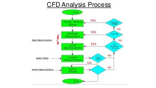
Working Of CFDCode
All the CFD codes contain three main elements. They are as follows,
• Pre processor.
• Solver.
• Post processor.
Advantages and Disadvantagesof CFD
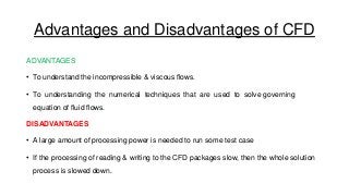
ADVANTAGES
• To understand the incompressible & viscous flows.
• To understanding the numerical techniques that are used to solve governing
equation of fluid flows.
DISADVANTAGES
• A large amount of processing power is needed to run some test case
• If the processing of reading & writing to the CFD packages slow, then the whole solution
process is slowed down.
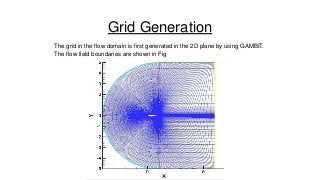
Grid Generation
The gridin the flow domain is first generated in the 2D plane by using GAMBIT.
The flow field boundaries are shown in Fig
19.
Results And Discussions
TheCFD solution for different hydrofoils for various angles of attacks is
presented are
• Surface pressure.
• Skin friction.
• Streamline pattern.
• Lift and drag characteristics.
20.
Blockage Effect inTunnel Testing
• CFD analysis is also done to examine the effect of a wall, if it presents in proximity to the
wing.
• This situation may arise when the same is tested in wind tunnel or in cavitation tunnel and
the blockage is too high.
• A wall condition is defined in the problem at different distances from the foil as shown in
the Fig.
• It is observed that when the wall is too close to the foil it significantly effects the lift of the
section but as the wall is pushed far away fro the section the effect reduces.
• When the wall is shifted at 4L distance from the foil the effect is almost minimized.
25.
Conclusion
• It hasbeen concluded that marine applications such as radars where large
angle of attack required, thicker sections like NACA 0015, NACA 0018,NACA
0024, and NACA 16-021 are recommended.
• It has been concluded that the lifting surfaces like hydrofoil crafts, where
small angle of attack thinner sections NACA 0006 and NACA 66-012 are
recommended.