7.pdf This presentation captures many uses and the significance of the number...
Ws2000 wireless switch installation guide
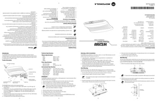
1. (2) (1)
Revision A May 2007
72-100065-01
• WS2000 Quick Installation Guide
• WS2000 Quick Installation Guide • Rubber plug for CompactFlash® slot
bracket and bezel (already installed)
• Rack bezel Mounting screws for rack • Rubber plugs for bottom of housing (4)
socket-outlet. • Rack bracket • Rubber feet for desk mount option (4)
• For equipment that needs to be plugged in, position equipment near an easily accessible • #6 Wall anchors for wall mount (4) • Ethernet CAT-5 patch cable (1)
the equipment. • #6 mounting screws for wall bracket (4) • Power supply with line cord http://www.motorola.com
• Verify uninterruptible power sources—install the socket nearby and easily accessible to • Wall mount bracket • Clear snap-on face plate SCHAUMBURG, IL60196
equipment operation specifications. (KT-MTDP-WS-2000-WW or KT-MTG-WS-2000-WW) • WS2000 Wireless Switch 1303 E ALGONQUIN ROAD
• Verify adequate ventilation around the device and that ambient temperatures meet (Sold Separately) MOTOROLA, INC.
weather conditions where power surges can exist. Mounting Accessories Box WS2000 Wireless Switch Box
• Do not install this equipment or work with its power circuits during thunderstorms or representative. The packages should contain the following:
• Do not work with equipment power circuits in dimly lit spaces. Inspect the package contents and report any missing or damaged items to your sales +44 118 945 7360 Distributor Operations
overloaded. Contact local distributor or call Europe/Mid-East
Verifying Package Contents
• Verify the power circuit for the unit is grounded, can provide the required power and is not +1-954-255-2610 Outside US Sales Support
equipment. 1-800-347-0178 Inside US Latin America
• Verify the power connector is accessible at all times during the operation of the trained personnel should attempt to correct or perform. Outside Spain
• Attach only approved power cords to the device. Indicates a potentially dangerous condition or procedure that only Motorola- +34 91 324 40 00 84452900 Sweden/Sverige
• Verify connecting power circuits have appropriate overload protection. Inside Spain
• Verify that any device connected to this unit is properly wired and grounded. Care is required. Disregarding cautions can cause data loss or equipment damage. 91 324 40 00 Spain/España 11-8095311 South Africa
cords to a properly wired and grounded electrical circuit. +47 2232 4375 Norway/Norge 315-271700 Netherlands/Nederland
• Verify the unit is grounded before connecting to the power source. Connect all power 5-520-1835 Mexico/México 2-484441 Italy/Italia
occur from equipment that was not appropriately mounted and secured. Indicates tips, hints and special requirements 6074-49020 Germany/Deutschland 01-40-96-52-21 France
tip over and break away from its mountings. Damage to the device or bodily injury can
• Verify that racks are anchored and do not install in a way that can cause the equipment to 9 5407 580 Finland/Suomi 7020-1718 Denmark/Danmark
Note the following icon conventions that are used throughout the document 1-505-5794-0 Austria/Österreich 1-800-672-906 Australia
• Install this equipment in racks with appropriate dimensions and weight allowances.
• Remove any jewelry (rings, watches, necklaces, etc.) while installing this equipment. Document Conventions +65-6796-9600 Asia/Pacific 0800 328 2424 United Kingdom
installation, before connecting the system to its power source. and site network analysis. Installation Guide 1-631-738-2400
• Read all installation instructions and site survey reports. Verify correct equipment specific installation procedures see the site-specific documentation derived from site survey Wireless Switch 905-629-7226 Canada 1-800-653-5350 United States
• Only trained and qualified personnel should install this equipment. installation process. It does not give site-specific installation instructions. For detailed site-
installation and use of the device. Also, review standard practices for preventing accidents concepts. This guide provides specifications, procedures, and guidelines to use during the
Switch. It assumes that the technician is familiar with basic Ethernet LAN-based networking
WS2000 contact the Motorola Support Center:
facility’s Technical or Systems Support. If there is a problem with the equipment, they will
Before operating any equipment, review this document for any hazards associated with applications. If you have a problem running your unit or using your equipment, contact your
This guide is intended to assist the technician responsible for installing the WS2000 Wireless
Before using the unit, it must be configured to operate in the facility’s network and run your
Warnings To the Installer Service Information
Introduction Technical Specifications Selecting a Site for Installation 4. Return the switch to the upright position in the place that you wish it to sit, ensuring that
The WS2000 Wireless Switch provides centralized management of wireless network The WS2000 can be installed on a flat surface, a wall, or in a rack. When selecting a site, the it is sitting evenly on all four rubber feet.
Physical Specifications
components across a wired network infrastructure. This wireless switch can connect directly installer should verify the location has access to: 5. Connect the power supply to the wall outlet.
to a cable or DSL modem, and can also connect to other wide area networks through a Layer 2 Width 286mm (11.26in.)
Height 45mm (1.75in.) • A grounded outlet—preferably one that has surge protection or is protected by an Wall Mounting
or 3 device (such as a switch or router).
Depth 203mm (7.99in.) uninterruptible power supply (UPS) The wall mount bracket option secures the unit to most walls using the four screws included
Product Description Weight 0.64kg (1.41lbs) • The WAN connection for the switch (whether a modem, router, switch, or hub). in the mounting accessories box. The wall mounting accessories are sold separately from the
(The wireless switch comes with a 6ft. (1.829m) patch cable for this purpose, but the switch (KT-MTDP-WS-2000-WW or KT-MTG-WS-2000-WW).
Power Specifications installer is not required to use either that cable or stay within that distance.)
AC Power Connection Operating Voltage 48VDC • The LAN connections for this switch (whether access port, switch, hub, or computer). 1. Remove the protective rubber plugs from the switch as shown.
Operating Current 1A, Peak Current 1.6A Ensure this location meets optimal temperature and environmental requirements for the
operation of this device (see Technical Specifications).
Environmental Specifications
Operating Temperature 0°C to 40°C (32°F to 104°F)
Desk Mounting
Serial Port
Storage Temperature -40°C to 70°C (-40°F to 158°F) The desk mount option uses rubber feet which allow the unit to sit on most flat surfaces.
Operating Humidity 10% to 85% Non-condensing The four (4) round rubber feet can be found in the WS2000 (main) box in a separate plastic bag.
CompactFlash® Slot Storage Humidity 10% to 85% Non-condensing 1. Turn the switch upside down so the side with the power connector is facing up.
Power LED Operating Altitude 2.4km (1.49mi)
2. Connect the power supply to the switch as shown in diagram.
Storage Altitude 4.6km (2.86mi)
To snap into the wall mount bracket, the protective rubber plugs must be removed.
Clear Face Plate Installation Do not attach the power supply to the wall outlet until installation of the switch
The WS2000 can operate in various locations, allowing placement in most environments. Basic is complete. 2. Using the screws and wall anchors supplied in the mounting accessories box, attach the
Rubber Plug for installation steps entail the following: wall mount bracket to the wall as shown.
CompactFlash® Slot 3. Remove the backings from the four (4) rubber feet and stick them to the switch on the four
1. Snap clear face plate (in WS2000 main box) onto the front-right side of the switch. Align the RJ-45 ports on the switch with the embossed port symbols on the front
4 LAN (RJ-45) Ports 2 LAN (RJ-45) Ports WAN Port circles, as shown. The feet will be right next to the four plugs. of the wall mount bracket.
With Power Without Power 2. Select a site (desk, wall, or rack) for installation of the wireless switch.
Power Plug Connector
3. Install in selected location using the instructions specifically for that location type. Rubber Plugs
Wall
The WS2000 Wireless Switch has the following features: Connect the wireless switch to the power supply early in the installation process
• One WAN port for connection to a DSL modem, cable modem, or any other Layer 2/3 for easy access to the connector; however, do not plug the power supply into a
network device. power source before installation is complete.
• Six LAN ports—four ports provide 802.3af Power over Ethernet (PoE) support, the other Embossed
two do not provide power. Each port has two LEDs, one indicating the speed of the 4. Plug the wireless switch into the wall power socket. Port Symbols
transmission (10Mbits/sec. or 100Mbits/sec.), the other indicating whether there is 5. Lock device to desk, wall, or rack using lock port on the switch.
activity on the port. 6. Plug in WAN and LAN (Access Port) connections.
• A serial port for direct access to the command-line interface from a PC. Use a DB-9 female
7. Configure the product for your network and devices (see the WS2000 Wireless Switch
to female null modem cable to connect to this port.
• A CompactFlash® slot provides administrative functions. System Reference available on the Motorola website).
(3) (4) (5) (6)
2. 3. Connect the power supply to the switch, but not to the wall outlet. Connecting to WAN and LAN (RJ-45) Ports Customer Support Web Sites Waste Electrical and Electronic Equipment (WEEE)
The WS2000 Wireless Switch provides six LAN ports and one WAN port. LAN Ports 1-4 Comprehensive On-line support is available at the Support Central at
Do not attach the power supply to the wall outlet until installation of the switch is provide 802.3af PoE support. The WAN port is capable of hooking up to a DSL or cable modem, http://www.symbol.com/support. Support Central provides our customers with a wealth of English: For EU Customers: All products at the end of their life must be returned to Motorola
complete. or to any Layer 2/3 network device information and online assistance including developer tools, software downloads, product for recycling. For information on how to return product, go to:
Standard Ethernet Ports
manuals and online repair requests. http://www.symbol.com/environmental_compliance
4. Align the holes on the bottom of the switch (where the plugs used to be) with the plastic Downloads
guides on the mounting bracket (circled in diagram).
http://www.symbol.com/downloads/
Manuals
Dansk: Til kunder i EU: Alle produkter skal returneres til Motorola til recirkulering, når de er
http://www.symbol.com/manuals/ udtjent. Læs oplysningerne om returnering af produkter på:
http://www.symbol.com/environmental_compliance
802.3af LAN Ports WAN Port Power LED Additional Information
Deutsch: Für Kunden innerhalb der EU: Alle Produkte müssen am Ende ihrer Lebensdauer zum
(PoE) Obtain additional information by contacting Motorola at: Recycling an Motorola zurückgesandt werden. Informationen zur Rücksendung von Produkten
1-800-722-6234, inside North America finden Sie unter http://www.symbol.com/environmental_compliance
+1-631-738-5200, in/outside North America Eesti: EL klientidele: kõik tooted tuleb nende eluea lõppedes tagastada taaskasutamise
Plug devices into RJ-45 ports using standard CAT-5 patch cables. http://www.motorola.com/ eesmärgil Motorola'ile. Lisainformatsiooni saamiseks toote tagastamise kohta külastage palun
aadressi: http://www.symbol.com/environmental_compliance
Regulatory Information
Español: Para clientes en la Unión Europea: todos los productos deberán entregarse a
This device is approved under the Symbol Technologies brand; Symbol Technologies, Inc., is the Motorola al final de su ciclo de vida para que sean reciclados. Si desea más información sobre
Enterprise Mobility business of Motorola, Inc (“Motorola”). cómo devolver un producto, visite: http://www.symbol.com/environmental_compliance
The power LED flashes during startup and remains lit during normal operation.
All Motorola devices are designed to be compliant with rules and regulations in locations they are
sold and will be labeled as required. Local language translations are available at the following
5. Push the switch into place on the bracket. You should hear a snap indicating that the switch Each Ethernet port has two LEDs. The LED on the left hand side of the port indicates whether website: http://www.symbol.com/manuals/. Any changes or modifications not expressly
is securely attached to the bracket. the port is transmitting at 10Mbits/sec. or 100Mbits/sec. The light is off when transmitting at approved by Motorola could void the user’s authority to operate the equipment.
10Mbit/sec. The light is on when transmitting at 100Mbits/sec.The LED on the right side Wireless Devices - Country Selection
6. Connect the power supply to the wall outlet. indicates an Ethernet link or activity on that port. This light is on solidly when a link to a device
Select only the country in which you are using the device. Any other selection will make the Français : Clients de l'Union Européenne : Tous les produits en fin de cycle de vie doivent être
The wall mount bracket is designed to allow threading of cables underneath the is made. The light flashes when traffic is being transferred over the line. operation of this device illegal. retournés à Motorola pour recyclage. Pour de plus amples informations sur le retour de
bracket. There is space underneath the wall mount bracket to hold cables. The four ports that have PoE capabilities also have a PoE LED on the bottom of the port. A green produits, consultez : http://www.symbol.com/environmental_compliance
Cables can be place above, between, or below the attachment points. light indicates 48 volts is being delivered to the power device connected to that port. A red light Italiano: Per i clienti dell'UE: tutti i prodotti che sono giunti al termine del rispettivo ciclo di
indicates the power device on the port is faulty. Once set to red, the light will remain red until vita devono essere restituiti a Motorola al fine di consentirne il riciclaggio. Per informazioni
Rack Mounting a non-faulty device is installed. If a non-power device is connected to the port, the PoE light will sulle modalità di restituzione, visitare il seguente sito Web:
remain off. http://www.symbol.com/environmental_compliance
The rack mounting option provides a 1U bracket to the switch allowing it to be mounted in a
standard rack. Rack mounting accessories are sold separately from the wireless switch (KT-
MTDP-WS-2000-WW or KT-MTG-WS-2000-WW). For Rack Mounting instructions please see
the instructions included with the rack mounting kit.
(7) (9) (11) (13)
Securing the Network Switch Customer Support Radio Frequency Interference Requirements - FCC
The WS2000 comes with a lock port that is compatible with most locking systems. The lock port Motorola provides its customers with prompt and accurate customer support. Use Motorola Symbol Technologies Inc.
Note: This equipment has been tested and found to comply with
is on the rear of the switch, opposite the power connector. In order to have clear access, We Support Central as the primary contact for any technical problem, question or support issue the limits for a Class B digital device, pursuant to Part 15 of the
Tested to Comply
suggest that you lock the wireless switch in place before you plug in WAN and LAN cables. involving Motorola products. If the support specialists cannot solve a problem, access to all With FCC Standards FCC rules. These limits are designed to provide reasonable
technical disciplines becomes available for further assistance and support. Motorola Support For Home or Office Use protection against harmful interference in a residential Magyar: Az EU-ban vásárlóknak: Minden tönkrement terméket a Motorola vállalathoz kell
Lock Port installation. This equipment generates, uses and can radiate eljuttatni újrahasznosítás céljából. A termék visszajuttatásának módjával kapcsolatos
Central responds to calls by email, telephone or fax within the time limits set forth in individual
contractual agreements. radio frequency energy and, if not installed and used in accordance with the instructions, may tudnivalókért látogasson el a http://www.symbol.com/environmental_compliance
Back cause harmful interference to radio communications. However there is no guarantee that
When contacting Motorola Support Central, please provide the following information: interference will not occur in a particular installation. If this equipment does cause harmful
• Serial number of unit interference to radio or television reception, which can be determined by turning the equipment
• Model number or product name off and on, the user is encouraged to try to correct the interference by one or more of the following
• Software type and version number measures: Nederlands: Voor klanten in de EU: alle producten dienen aan het einde van hun levensduur
naar Motorola te worden teruggezonden voor recycling. Raadpleeg
North American Contacts • Reorient or relocate the receiving antenna http://www.symbol.com/environmental_compliance voor meer informatie over het
Inside North America, contact Motorola at: • Increase the separation between the equipment and receiver terugzenden van producten.
For sales and product information: • Connect the equipment to an outlet on a circuit different from that to which the receiver is
Power Connector connected
Motorola, Inc. • Consult the dealer or an experienced radio/TV technician for assistance
One Motorola Plaza
Using the CompactFlash® Slot Radio Frequency Interference Requirements - Canada
Holtsville, New York 11742-1300
The WS2000 wireless switch has a CompactFlash® slot which provides administrative Telephone: 1-631-738-2400/1-800-SCAN 234 This Class B digital apparatus complies with Canadian ICES-003. Português: Para clientes da UE: todos os produtos no fim de vida devem ser devolvidos à
functions. When not being used for this purpose, the rubber plug provided with the switch Fax: 1-631-738-5990 Cet appareil numérique de la classe B est conforme à la norme NMB-003 du Canada. Motorola para reciclagem. Para obter informações sobre como devolver o produto, visite:
should remain in the slot. http://www.symbol.com/environmental_compliance
For product support and service: Marking and European Economic Area (EEA) Slovenski: Za kupce v EU: vsi izdelki se morajo po poteku življenjske dobe vrniti podjetju
Support Center: Motorola za reciklažo. Za informacije o vraèilu izdelka obišèite:
Telephone: 1-800-653-5350, +1-631-738-6213 (Outside North America) http://www.symbol.com/environmental_compliance
Fax: 631-563-5410 Power Supply
http://www.symbol.com/support Use only a Motorola approved power supply output rated at 48Vdc and minimum 2.2A.
International Contacts The power supply shall be Listed to UL/CSA 60950-1; and certified to IEC60950-1 and EN60950-1
with SELV outputs. Use of alternative power supply will invalidate any approval given to this
Outside North America: device and may be dangerous.
Motorola, Inc. Suomi: Asiakkaat Euroopan unionin alueella: Kaikki tuotteet on palautettava kierrätettäväksi
Winnersh Triangle, Berkshire, RG41 5TP Statement of Compliance Motorola-yhtiöön, kun tuotetta ei enää käytetä. Lisätietoja tuotteen palauttamisesta on
Rubber Plug for United Kingdom Motorola hereby declares that this device is in compliance with all the applicable Directives, 89/ osoitteessa http://www.symbol.com/environmental_compliance
CompactFlash® Slot Telephone: 0800-328-2424 (Inside UK), +44 118 945 7529 (Outside UK) 336/EEC, 73/23/EEC. A Declaration of Conformity may be obtained from: Svenska: För kunder inom EU: Alla produkter som uppnått sin livslängd måste returneras till
http://www2.symbol.com/doc/ Motorola för återvinning. Information om hur du returnerar produkten finns på
http://www.symbol.com/environmental_compliance
(8) (10) (12) (14)