1. CFS0077-UL-C_Layout 1 12/01/2012 11:43 Page 15
UL Listed Product Range
SIGNALING
Intelligent Addressable Standard Base 4AC5
FIRE ALARM
EQUIPMENT
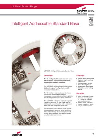
UCAB300 - Intelligent Addressable Standard Base
Overview Features
The UL intelligent addressable standard base • Integral sensor shorting link
(UCAB300) has been designed for flexibility, • Separate loop in and loop
out terminals
simplicity and speed of installation.
• Dedicated earth terminal
• Stand off fixing feature
The (UCAB300) is compatible with the Cooper • Accepts side entry cables
UL Listed range of intelligent addressable • Selectable sensor locking
sensors and fire systems. feature
The UL intelligent addressable standard base
host a range of intuitive features and
Benefits
incorporates a purpose designed shorting link to • Quick and simple to install
ensure wiring continuity if a sensor is removed. • Common mounting base
for Cooper UL intelligent
The (UCAB300) is designed to provide separate addressable sensors
connection terminals for loop in and loop out • Positive "lock" indication
cables up to 2.5mm2 together with a dedicated • multiple cable entry points
earth drain wire connection on the base. • Easy to maintain/service
This device also has a retaining clip to provide
positive feedback when the sensor is correctly
fitted and a retaining clip can be replaced with
locking device (supplied with base) to prevent
unauthorised sensor removal.
15
2. CFS0077-UL-C_Layout 1 12/01/2012 11:43 Page 16
UL Intelligent Addressable Standard Base - UCAB300
Dimensions Technical Specification
Dia (mm) D (mm) Code UCAB300
104 22 Description Standard Base
D Physical
Construction PC/ABS
Colour White
Dimensions (Dia x D) 104mm x 22mm
Dia
Compatibility
Suitable for use with Cooper UL Fire Systems
Utilising Locking Tab Installation
Mounting base includes an optional feature to 1. Separate terminals are provided for loop in
prevent the removal of the detector without the and loop out connections.
use of a tool. 2. Each terminal can accept up to 2 x 2.5mm
cables.
1. Remove the positive 1 3. Base incorporates a substantial cable entry
"lock" indication aperture in the rear of the base.
module (1). 4. Breakouts are provided to enable the sensor
2. Insert the locking base to sit neatly over surface run cables and
module that is then enter via the rear entry aperture.
located at the centre 5. The base incorporates a stand off feature to
of the base as help prevent distortion when mounted on an
shown (2). uneven surface.
2
6. Fixings are suitable for standard BESA box or
Mount the sensor onto the base and rotate fully direct fixing to a suitable surface.
clockwise until it finally clicks.
If difficulty is experienced when mounting the
The sensor is now locked into position. Remove detector, this may be due to the following:
by utilising a suitable tool (eg a thin screwdriver)
into the hole in the sensor cover. Gently push • Wiring causing an obstruction - move or
the tool into the sensor and rotate anticlockwise. shorten wires.
• The base is tolerant to uneven mounting
surfaces, a very uneven surface may cause
the base to deform when the mounting
screws are tightened down - loosen screws to
reduce this or reposition the base.
Standard Connection
+
remote indicator (optional)
+V
S+ 4 4
Intelligent Addressable
Loop start
E E
Compatible Cooper
S-
Control Panel
3 3
LED
LED
F-
Loop finish
1 1
F+
2 2
- VE OUT
- VE IN
Warning! earth screen of cable must be continuous
WARNING:
Do not use high voltage testers when detectors If using the outer connection on terminal 2, ensure the operation of the switch is not impeded
or control panel are connected to the system. and that there are no shorts between terminal 2 and the switch contact.
Product Codes
Code Description
UCAB300 Intelligent Addressable Standard Base
CIR301 Remote Indicator
16