This document discusses DNV Marine Operations' rules for subsea lifting. It provides an overview of relevant DNV publications and describes the capacity checks outlined in the 1996 rules for lifting operations. The document then introduces a new simplified method for calculating hydrodynamic forces during subsea lifts, which will be included in an upcoming DNV recommended practice. This method makes simplifying assumptions and provides equations to estimate forces like slamming impacts and varying buoyancy in a conservative manner.

![DNV Marine Operations' Rules for Subsea Lifting Slide 22
2 December 2008
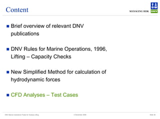
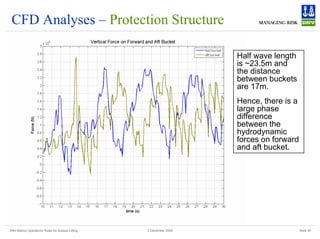
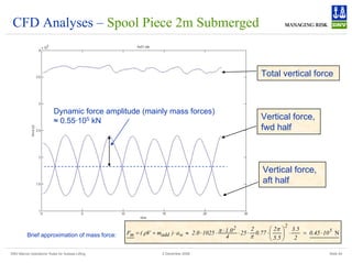
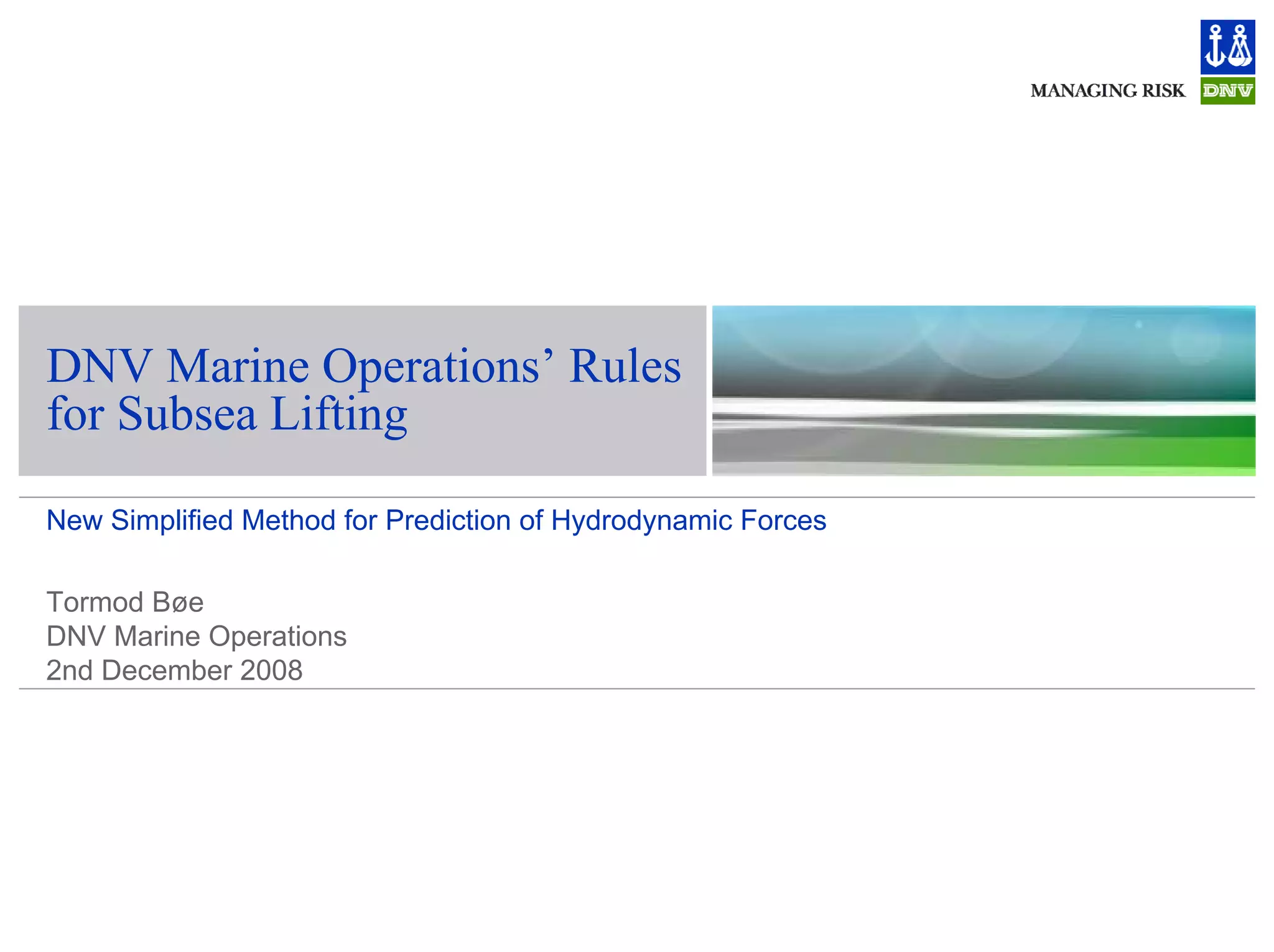
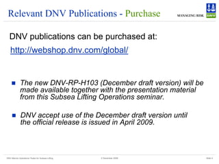
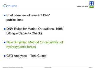
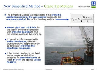
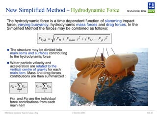
New Simplified Method – Hydrodynamic Forces
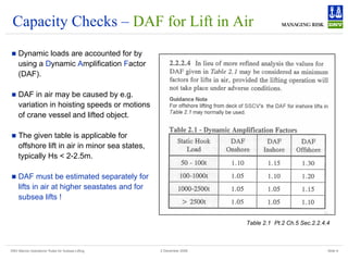
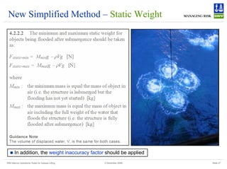
Drag force
Drag forces are flow resistance on
submerged part of the structure. The drag
forces are related to relative velocity between
object and water particles.
The drag coefficient, CD, in oscillatory flow for
complex subsea structures may typically be
CD ≥ 2.5.
Relative velocity are found by :
2
2
w
ct
c
r v
v
v
v +
+
=
„ vc = lowering/hoisting speed
„ vct = vertical crane tip velocity
„ vw = vertical water particle velocity
at water depth , d
„ Ap = horizontal projected area
Mass force
“Mass force” is here a combination of inertia
force, Froude-Kriloff force and diffraction
force.
Crane tip acceleration and water particle
acceleration are assumed statistically
independent.
( )
[ ] ( )
[ ]2
33
2
33 w
ct
M a
A
V
a
A
M
F ⋅
+
+
⋅
+
= ρ
„ M = mass of object in air
„ A33 = heave added mass of object
„ act = vertical crane tip acceleration
„ V = volume of displaced water relative to
the still water level
„ aw = vertical water particle acceleration
at water depth, d](https://image.slidesharecdn.com/liftingrulesexample-dnv-221025073155-29ab7b85/85/Lifting-Rules-Example-DNV-pdf-22-320.jpg)
![DNV Marine Operations' Rules for Subsea Lifting Slide 28
2 December 2008
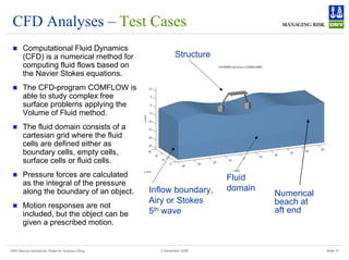
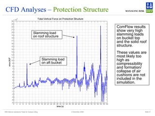
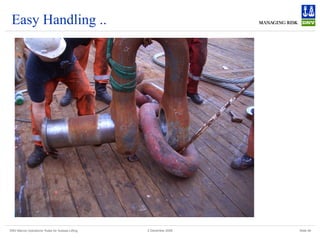
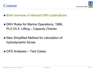
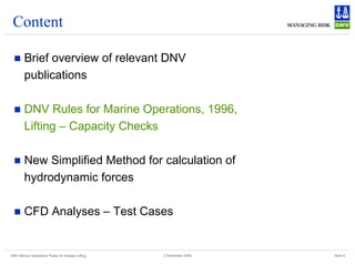
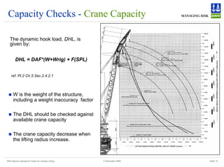
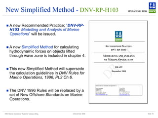
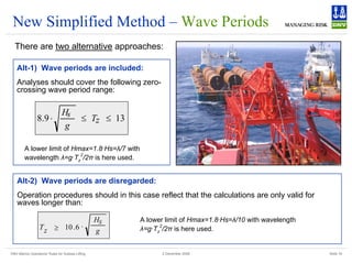
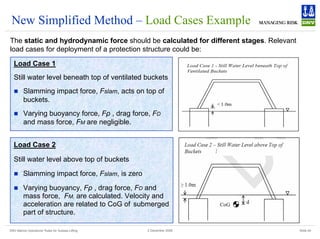
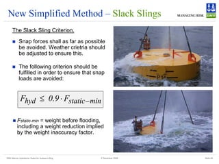
New Simplified Method - DAF
Capacity Checks
The capacities of crane, lifting equipment and
lifted object are checked as for lift in air. The
following relation should be applied:
where
Mg : weight of object in air [N]
Ftotal : is the characteristic total force on the
(partly or fully) submerged object. Taken as the
largest of;
Ftotal = Fstatic-max + Fhyd or
Ftotal = Fstatic-max + Fsnap
„ Fstatic-max is the maximum static
weight of the submerged object
including flooding and weight
inaccuracy factor
„ Fhyd is the hydrodynamic force
„ Fsnap is the snap load (normally
to be avoided)
Mg
F
DAF total
=](https://image.slidesharecdn.com/liftingrulesexample-dnv-221025073155-29ab7b85/85/Lifting-Rules-Example-DNV-pdf-28-320.jpg)
![DNV Marine Operations' Rules for Subsea Lifting Slide 31
2 December 2008
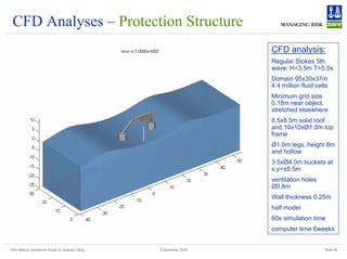
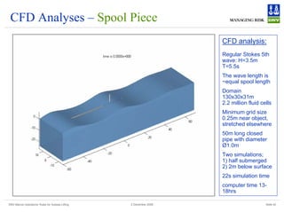
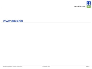
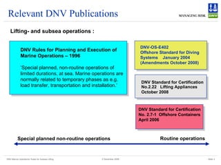
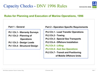
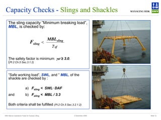
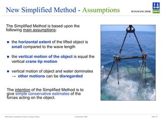
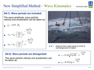
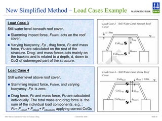
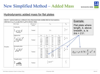
New Simplified Method – Added Mass
Added Mass Increase due to Body Height
The following simplified approximation of the
added mass in heave for a three-dimensional
body with vertical sides may be applied :
o
33
2
2
33 A
)
1
(
2
1
1
A ⋅
⎥
⎥
⎥
⎦
⎤
⎢
⎢
⎢
⎣
⎡
+
−
+
≈
λ
λ
p
p
A
h
A
+
=
λ
Added Mass Increase due to Body Height
1
1.1
1.2
1.3
1.4
1.5
1.6
1.7
1.8
0 0.5 1 1.5 2 2.5
ln [ 1+ (h/sqrt(A)) ]
A33/A33o
1+SQRT((1-lambda^2)/(2*(1+lambda^2)))
and
where
„ A33o = added mass for a flat plate with a
shape equal to the horizontal projected
area of the object
„ h = height of the object
„ Ap = horizontal projected area of the object](https://image.slidesharecdn.com/liftingrulesexample-dnv-221025073155-29ab7b85/85/Lifting-Rules-Example-DNV-pdf-31-320.jpg)
![DNV Marine Operations' Rules for Subsea Lifting Slide 33
2 December 2008
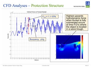
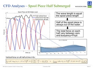
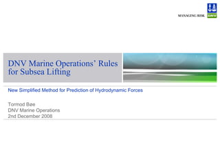
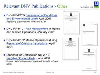
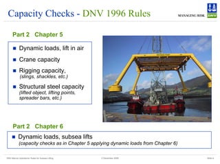
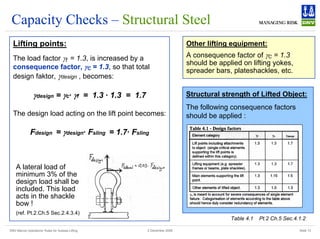
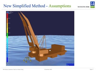
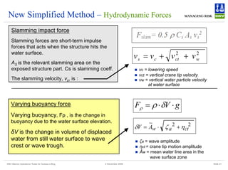
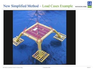
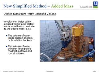
New Simplified Method – Added Mass
Added Mass Reduction due to Perforation
.
Effect of perforation on added mass
0
0.1
0.2
0.3
0.4
0.5
0.6
0.7
0.8
0.9
1
0 10 20 30 40 50
Perforation
Added
Mass
Reduction
Factor
e^-P/28
BucketKC0.1-H4D-NiMo
BucketKC0.6-H4D-NiMo
BucketKC1.2-H4D-NiMo
BucketKC0.5-H0.5D-NiMo
BucketKC1.5-H0.5D-NiMo
BucketKC2.5-H0.5D-NiMo
BucketKC3.5-H0.5D-NiMo
PLET-KC1-4
Roof-A0.5-2.5+
Hatch20-KCp0.5-1.8
Hatch18-KCp0.3-0.8
BucketKC0.1
BucketKC0.6
BucketKC1.2
RoofKCp0.1-0.27
RoofKCp0.1-0.37
DNV-Curve
Mudmat CFD
0
.
1
A
A
S
33
33
=
[ ]
34
/
)
5
p
(
cos
3
.
0
7
.
0
A
A
S
33
33
−
+
= π
28
p
10
S
33
33
e
A
A
−
=
if p< 5
if 5 < p < 34
if 34 < p < 50
Recommended reduction:
A33S = added mass for a non-
perforated structure.
„ No reduction applied in added mass when perforation is small. A significant drop in the
added mass for larger perforation rates. Reduction factor applicable for p<50.](https://image.slidesharecdn.com/liftingrulesexample-dnv-221025073155-29ab7b85/85/Lifting-Rules-Example-DNV-pdf-33-320.jpg)
![DNV Marine Operations' Rules for Subsea Lifting Slide 35
2 December 2008
New Simplified Method – Example Case
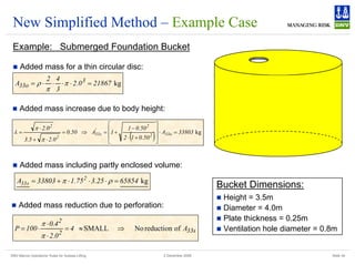
Example: Submerged Foundation Bucket
( ) N
5
2
2
2
r
P
D
D 10
37
.
0
48
.
1
25
.
0
0
.
2
96
.
0
0
.
2
5
.
0
v
A
C
5
.
0
F ⋅
=
+
⋅
⋅
⋅
⋅
=
⋅
⋅
⋅
⋅
= π
ρ
ρ
( )
[ ] ( )
[ ] ( ) N
5
2
w
33
2
ct
33
M 10
33
.
1
69
.
1
65854
13031
a
A
V
a
A
M
F ⋅
=
⋅
+
=
⋅
+
+
⋅
+
= ρ
2
m/s
and
m/s 69
.
1
v
5
.
5
2
a
48
.
1
e
5
.
5
2
75
.
1
v w
w
81
.
9
5
.
5
)
25
.
1
1
(
4
w
2
2
=
⋅
⎟
⎠
⎞
⎜
⎝
⎛
=
=
⋅
⎟
⎠
⎞
⎜
⎝
⎛
⋅
= ⋅
+
⋅
− π
π
π
Regular Wave Data:
„ Wave Height, Hmax = 3.5m
„ Wave Period, Tz = 5.5s
„ Water particle velocity and acceleration:
„ Drag force:
„ Mass force:
„ Hydrodynamic force:
1.0m
1.25m
CoG
Other Data
„ Buoyancy, ρV = 13031kg
„ Negligible crane tip motions
„ Lowering speed = 0.25m/s
( ) ( ) ( ) ( ) N
5
2
5
2
5
2
M
2
slam
D
hyd 10
4
.
1
10
33
.
1
10
37
.
0
F
F
F
F
F ⋅
=
⋅
+
⋅
=
−
+
+
= ρ](https://image.slidesharecdn.com/liftingrulesexample-dnv-221025073155-29ab7b85/85/Lifting-Rules-Example-DNV-pdf-35-320.jpg)