![The Zone Axis
1 2 3
uvw u v w
r a a a
1 2 3
hk h k
g b b b
0
hk uvw hu kv w
g r
Direct lattice vector:
Reciprocal lattice vector:
For all RLVs within the ZOLZ:
If 1 0
uvw
g r
2 0
uvw
g r
1 2 0
uvw
g g r
and
then
This is the [uvw] zone axis.
Any reflection (hkl) in the [uvw] ZOLZ has: 0
hu kv w
](data:image/gif;base64,R0lGODlhAQABAIAAAAAAAP///yH5BAEAAAAALAAAAAABAAEAAAIBRAA7)
Recommended
More Related Content
Similar to Reflections in a cubic structure
Similar to Reflections in a cubic structure (20)
Recently uploaded
Recently uploaded (20)
Reflections in a cubic structure
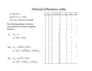
- 1. Allowed reflections: cubic sc: any , , bcc: even fcc: , , all even or all odd h k h k h k Note the dependence of atomic concentration on nearest-neighbor distance: n-n 3 3 n-n 1 1 d a a d n-n 3 3 3 n-n n-n 3 2 0.87 2 3 3 8 0.65 d a a a d d n-n 3 3 3 n-n n-n 2 0.71 4 2 1.41 d a a a d d sc: bcc: fcc:
- 2. The Zone Axis 1 2 3 uvw u v w r a a a 1 2 3 hk h k g b b b 0 hk uvw hu kv w g r Direct lattice vector: Reciprocal lattice vector: For all RLVs within the ZOLZ: If 1 0 uvw g r 2 0 uvw g r 1 2 0 uvw g g r and then This is the [uvw] zone axis. Any reflection (hkl) in the [uvw] ZOLZ has: 0 hu kv w
- 3. Finding the zone axis 1 2 || uvw g g If g1 and g2 reside in the [uvw] ZOLZ, then: Notice that: 1 2 3 1 2 1 1 1 2 2 2 1 h k V h k a a a g g So: 1 2 1 2 1 2 1 2 1 2 1 2 || , , uvw k k h h h k k h The zone axis of a ZOLZ in any crystal system satisfies the condition: i j j k i j k j j V a a a a a a a a a i j k V a a b j k i V a b b j k i V a a b
- 4. Determining Orientation Procedure: 1) measure d1 and d2 2) Determine (d2/d1)2 3) Look for integer ratio, consistent with fcc 4) Determine types of reflections 5) Select indices, based on angle Assume we know the structure (fcc), but not the lattice constant or orientation: 1 2 0.208 nm 0.293 nm d d 2 2 2 2 2 1 1 1 2 2 2 1 2 2 2 2 1.98 1 d h k d h k 4 2 6 3 2 2 2 2 2 2 8 2 2 0 4 2 0 0 (1): {220}, (2): {200} 1 2 0 (1) : 220, (2):002 g g [ ] 1 1 0 0,1 0 1 1,1 0 0 1 110 uvw B 110 6) Find zone axis Reconsider choice
- 5. Revise and index zone axis: 1 1 0 0,0 0 1 1,1 0 0 1 110 uvw B 110 2 002 002 2 2 0.586 nm a d d a d Find lattice constant: 1 002 220 111 2 111 002 000 113 220 220 change: 000 220 000 220 index:
- 6. Powder pattern (I): CdSe (1) :111 (2): 220 (3): 311 CdSe dots 2 2 2 2 2 2 2 2 1 8 2 2 0 2.66 3 1 1 1 d d Test fcc: ring 2/d (1/nm) d (nm) 1 5.677 0.352 2 9.251 0.216 3 10.858 0.1842 2 d d 2 2 2 2 3 2 2 2 1 11 3 1 1 3.66 3 1 1 1 d d
- 7. Powder Pattern (II): Gd2Ti2O4
- 8. Structure factor and intensity F f 1 e 0 i F f destructive interference constructive interference Inserting planes can reduce the intensities of some peaks. Waves scattered from inserted planes are 180° out-of-phase.