
Recommended
More Related Content
Similar to 3.steering.pptx
Similar to 3.steering.pptx (20)
Recently uploaded
Recently uploaded (20)
3.steering.pptx
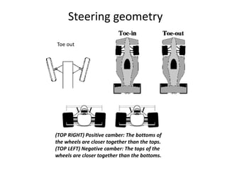
- 1. Steering geometry Toe out (TOP RIGHT) Positive camber: The bottoms of the wheels are closer together than the tops. (TOP LEFT) Negative camber: The tops of the wheels are closer together than the bottoms.
- 3. camber angle
- 4. Camber Camber is the tilt of the car wheels from the vertical. Camber is positive if the tilt is outward at the top. Camber is also called “wheel rake”. Camber should not generally exceed 2°. However the exact amount of camber is specified taking into account the king pin inclination. King Pin Inclination (Steering axis Inclination) Inclination of the king pin from vertical is called the king pin inclination or king pin rake. Effect :-King pin inclination helpsthe straight ahead recovery, thus provides stability. Amount : About 7 to 8 degrees
- 5. Combined angle Combined angle or included angle is the angle formed in the vertical plane between the wheel centre line and the king pin centre line ( or steering axis). Combine angle is equal to camber plus king pin inclination. Combined angle may be 9-10 degrees. And the scrub radius should be upto about 12mm Scrub radius The forward tractive force acts at the point on the road where the steering axis or the king pin axis meet when projected. The road resistance acts at the wheel contact point on the road. The distance between these two points is called scrub radius.
- 6. caster angle
- 15. STEERING LINKAGES A steering linkage is a combination of rods and arms that transmit movement of the steering gear to the front wheels, while allowing for wheel movement while the vehicle is in motion.
- 17. The pitman arm transfers steering mechanism motion to the steering linkag The pitmanarm is splined to the steering mechanisms output shaft(pitman arm shaft). A large nut and lock washer securethe pitman arm to the output shaft. The outer end of the pitman arm normally uses a ball-and-socket joint connect to the center link. Centre link is simply a steel bar thatconnects the steering arms (pitman arm, tie- rod ends,and idler arm) together. The turning action of the steering mechanism is transmitted to the center link through the pitman arm The center link is hinged on the opposite end of the pitman arm by means of an idler arm. Theidler arm supports the free end of the center link andallows it to move left and right with ease. The idler armbolts to the frame or subframe Ball sockets are like small ball joints;they provide for motion in all directions between twoconnected components. Ball sockets are needed so thesteering linkage is NOT damaged or bent when thewheels turn or move up and down over rough roads.Ball sockets are filled with grease to reduce frictionand wear. Some h ave a grease fitting that allowschassis grease to be inserted with a grease gun. Othersare sealed by the manufacturer and cannot be serviced
- 25. The arms and rods of the steering linkage have ballends or ball-and- socket ends to provide a swivelconnection between them. These joined ends haveg rease fittings, dust seals or boots, and many of themhave end-play adjustment devices. These joints anddevices must be adjusted and lubricated regularly The arms, rods, and joints of steering linkage in yourequipment may be arranged differently from thoseshown in figure, but you will find them in the samegeneral location in the front and underneath the vehicle. The tie rod is usually behind the axle and keeps thefront wheels in proper alignment. The tie rod is dividedinto two lengths and is connected to the steering gearnear the center of the vehicle to provide for easiersteering and maximum leverage. The drag link between the steering arm and thepitman arm may be long or short, depending on theinstallation The pitman arm is splined to the shaft extendingfrom the steering gear case. It moves in an arc with itsposition, depending on which direction the steeringwheel is turned. The arm is vertical when the frontwheels are straight ahead. Therefore, the length of thedrag link is determined by the distance between thesteering arm and the vertical position of the pitman arm.Unlike the tie rods, the length of the drag link is fixed.