Load Sharing for Parallel Operation of Gas Compressors
•
8 likes•1,727 views

The art of load sharing between centrifugal compressors consists of maintaining equal throughput through multiple parallel compressors. These compressors consist of a common suction and discharge header. Programmable logic controllers (PLCs) can be incorporated with load sharing functions or can be incorporated as standalone controllers also. Control signals from shared process parameters such as suction header pressure or discharge header pressure can be then fed to individual controllers such as compressor speed controllers (SC) or anti-surge controllers (UIC) to ensure the overall load is distributed efficiently between the compressors. The following article covers load sharing schemes for parallel centrifugal compressor operation.

Recommended
Recommended
More Related Content
What's hot
What's hot (20)
Similar to Load Sharing for Parallel Operation of Gas Compressors
Similar to Load Sharing for Parallel Operation of Gas Compressors (20)
More from Vijay Sarathy
More from Vijay Sarathy (20)
Recently uploaded
Recently uploaded (20)
Load Sharing for Parallel Operation of Gas Compressors
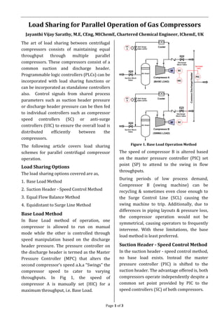
- 1. Page 1 of 3 Load Sharing for Parallel Operation of Gas Compressors Jayanthi Vijay Sarathy, M.E, CEng, MIChemE, Chartered Chemical Engineer, IChemE, UK The art of load sharing between centrifugal compressors consists of maintaining equal throughput through multiple parallel compressors. These compressors consist of a common suction and discharge header. Programmable logic controllers (PLCs) can be incorporated with load sharing functions or can be incorporated as standalone controllers also. Control signals from shared process parameters such as suction header pressure or discharge header pressure can be then fed to individual controllers such as compressor speed controllers (SC) or anti-surge controllers (UIC) to ensure the overall load is distributed efficiently between the compressors. The following article covers load sharing schemes for parallel centrifugal compressor operation. Load Sharing Options The load sharing options covered are as, 1. Base Load Method 2. Suction Header - Speed Control Method 3. Equal Flow Balance Method 4. Equidistant to Surge Line Method Base Load Method In Base Load method of operation, one compressor is allowed to run on manual mode while the other is controlled through speed manipulation based on the discharge header pressure. The pressure controller on the discharge header is termed as the Master Pressure Controller (MPC) that alters the second compressor’s speed a.k.a “Swings” the compressor speed to cater to varying throughputs. In Fig 1, the speed of compressor A is manually set (HIC) for a maximum throughput, i.e. Base Load. Figure 1. Base Load Operation Method The speed of compressor B is altered based on the master pressure controller (PIC) set point (SP) to attend to the swing in flow throughputs. During periods of low process demand, Compressor B (swing machine) can be recycling & sometimes even close enough to the Surge Control Line (SCL) causing the swing machine to trip. Additionally, due to differences in piping layouts & pressure loss, the compressor operation would not be symmetrical, causing operators to frequently intervene. With these limitations, the base load method is least preferred. Suction Header - Speed Control Method In the suction header - speed control method, no base load exists. Instead the master pressure controller (PIC) is shifted to the suction header. The advantage offered is, both compressors operate independently despite a common set point provided by PIC to the speed controllers (SC) of both compressors.
- 2. Page 2 of 3 Figure 2. Suction Header Speed Control Method It may be noted that both compressors would not necessarily be running at the same speed or flow due to differences in the piping layout as well as during a compressor recycle since both anti-surge controllers (UIC A/B) also act independently of each other. To ensure no production losses, the configuration consists of standby machine along with working compressors. During the failure of one of the compressor, say machine A, the PIC issues a signal to increase the speed of compressor B, until the standby compressor can be brought online to maintain throughput. In case of layouts that have no standby compressors, a 2 50% configuration, with no recycle during regular operation must be chosen. This enables the remaining working compressor to cater to 100% of the throughput/load at higher speeds during failure of the one of the compressors. Equal Flow Balance Method In the equal flow balance method, the Master Pressure Controller (PIC) on the common discharge header determines the total load demand and alters the speeds of Compressors A & B via SC. The individual flow control signal to each speed controller is achieved by scaling the total load demand (BIAS A & BIAS B) to the individual flow controller (FC) on each compressor. Both Compressor operations are independent of the Anti-surge valve (ASV) operation. Figure 3. Suction Header Speed Control Method However certain limitations exist with the flow balancing method. Due to additional control elements, CAPEX cost increases. Furthermore since the flow element & transmitter (FT) is installed on the compressor discharge, additional pressure drop occurs which represents energy losses. For the cascaded control used, PIC FC SC, the inner loop (FC) must respond faster than the PIC outer loop. This causes the master pressure control, PIC to be sluggish. A faster FC loop also means, the compressor speed would increase rapidly than required often reaching maximum speed. Hence this does not offer the best control strategy. Equidistant to Surge Line Method In the equidistant method, the aim is to ensure, the deviation/distance between the operating point and the surge control line (SCL) in both trains is equidistant.
- 3. Page 3 of 3 Figure 4. Equidistant to Surge Line Method In this configuration, neither the throughputs through each compressor or the operating compressor speed is the same, but only the deviation between the operating point & SCL. It may also be noted that the load sharing function (LSIC A/B) that alters the compressor speed, is not fed with the signal from the suction flow transmitter (FT), but instead the anti-surge controller (UIC A/B) and the master pressure controller (PIC) installed on the common discharge header. This would mean, both UIC A/B and LSIC A/B have to coordinate in real time. A significant advantage of the equidistant to surge line method is the configuration’s ability to cater to asymmetrical performance curves, i.e., dissimilar compressors. In brownfield modifications, any addition of new compressors can offer synchronicity issues including variation in throughputs & pressures due to differences in performance curves & piping layouts. Therefore the equidistant method becomes an effective configuration for varying loads ensuring both compressors independently adjust their respective operations and avoid surge. Some Design Considerations 1. The Master pressure controller which provides shared information across all compressors can often be subjected to harsh field conditions. To circumvent these issues, redundancy with multiple transmitters can be provided. This ensures not only maximum availability but also hardwiring the transmitters prevents any loss of signals to the Load sharing system. 2. Depending on the reliability of the control systems, controllers need to be replaced sometimes with third party OEM vendors, each with their own proprietary control systems. Hence load sharing systems must be able to integrate different vendors. 3. Real Time optimization (RTO) techniques based on regression models of steady state data have gained sufficient footing in recent years. Short Time RTO of the order of a few minutes & Long term RTO of the order of a few days can be employed to determine the best load distributions between compressors. References 1. “Advanced Load Sharing Controls for Compressor Networks”, Alex Benim, Brian Eldridge, Woodward Inc.