(INDIRA) Call Girl Bhosari Call Now 8617697112 Bhosari Escorts 24x7
Gas Turbine Power Plant
1. 4/21/2018
1
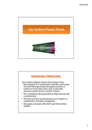
Gas Turbine Power Plants
WORKING PRINCIPAL
Gas turbine engines derive their power from
burning fuel in a combustion chamber and using
the fast flowing combustion gases to drive a
turbine in much the same way as the high
pressure steam drives a steam turbine.
• Air is compressed (squeezed) to high pressure by
a compressor
• The fuel and the compressed air are mixed in a
combustion chamber and ignited
• Hot gases are given off which spin the turbine
wheels.
2. 4/21/2018
2
WORKING PRINCIPAL
• Positive feedback mechanism
As the gas turbine speeds up, it also causes the
compressor to speed up forcing more air through
the combustion chamber which in turn increases
the burn rate of the fuel sending more high
pressure hot gases into the gas turbine increasing
its speed even more. Uncontrolled runaway is
prevented by controls on the fuel supply line
which limit the amount of fuel fed to the turbine
thus limiting its speed.
Brayton Cycle
• Gas turbines are described thermodynamically by the
Brayton cycle
• In this cycle:
1. air is compressed isentropically
2. combustionoccurs at constant pressure
3. heated air expands through the turbine
4. heat is rejected into the atmosphere
3. 4/21/2018
3
Main Components
• Gas turbines burn fuels such as oil, natural gas
and pulverized (powdered) coal.
• Gas turbine has three main parts
1. Compressor
2. Combustion chamber
3. Turbine
5. 4/21/2018
5
9
Gas Turbine components
Inlet system Collects and directs air into the gas turbine. Often, an air cleaner and
silencer are part of the inlet system. It is designated for a minimumpressure drop
while maximizing clean airflow into the gas turbine.
Compressor Provides compression, and, thus, increases the air density for the
combustion process. The higher the compression ratio, the higher the total gas
turbine efficiency . Low compressor efficiencies result in high compressor discharge
temperatures, therefore, lower gas turbine output power.
Combustor Adds heat energy to the airflow. The output power of the gas turbine is
directly proportional to the combustor firing temperature; i.e., the combustor is
designed to increase the air temperature up to the materiallimits of the gas turbine
while maintaining a reasonable pressure drop.
* Gas turbines are not self starting therefore a startingmotor is used.
10
Gas Producer Turbine Expands the air and absorbs just enough energy
from the flow to drive the compressor. The higher the gas producer
discharge temperature and pressure, the more energy is available to
drive the power turbine, therefore, creating shaft work.
Power Turbine Converts the remaining flow energy from the gas
producer into useful shaft output work. The higher the temperature
difference across the power turbine, the more shaft output power is
available.
Exhaust System Directs exhaust flow away from the gas turbine inlet.
Often a silencer is part of the exhaust system. Similar to the inlet
system, the exhaust system is designed for minimum pressure losses.
6. 4/21/2018
6
Fuels
• Advantage of gas turbines is fuel flexibility
• Can be adapted to use almost any flammable gas
or light distillate petroleum products such as
gasoline (petrol), diesel and kerosene (paraffin)
which happen to be available locally, though
natural gas is the most commonly used fuel.
• Crude and other heavy oils and can also be used
to fuel gas turbines if they are first heated to
reduce their viscosity to a level suitable for
burning in the turbine combustion chambers.
Applications
• Gas turbines can be used for large scale power generation.
Examples are applications delivering 600 MW or more from
a 400 MW gas turbine coupled to a 200 MW steam turbine
in a co-generating installation. Such installations are not
normally used for base load electricity generation, but for
bringing power to remote sites such as oil and gas fields.
They do however find use in the major electricity grids
in peak shaving applications to provide emergency peak
power.
• Low power gas turbine generating sets with capacities up
to 5 MW can be accommodated in transportation
containers to provide mobile emergency electricity supplies
which can delivered by truck to the point of need.
• Aircrafts, ships and high speed cars.
7. 4/21/2018
7
Electrical Power Generation
• In electricity generating applications the
turbine is used to drive a synchronous
generator which provides the electrical power
output but because the turbine normally
operates at very high rotational speeds of
12,000 r.p.m or more it must be connected to
the generator through a high ratio reduction
gear since the generators run at speeds of
1,000 or 1,200 r.p.m. depending on the AC
frequency of the electricity grid.
Turbine Configurations
• Gas turbine power generators are used in two
basic configurations
• Simple Systems consisting of the gas turbine
driving an electrical power generator.
8. 4/21/2018
8
System Efficiency: Simple Cycle
Turbines
• GT consumes considerable amounts of power just to drive its
compressor.
• Higher maximum working temperature in the machine means
greater efficiency but also more energy loss as waste heat through
the hot exhaust gases whose temperatures are typically well over
1,000°C .
• Simple cycle turbine efficiencies are quite low. For heavy plant,
design efficiencies range between 30% and 40%. Aero engines [38%
- 42% . Low power microturbines (<100kW) : 18% - 22%.
• Increasing the firing temperature increases the output power at a
given pressure ratio, there is also a sacrifice of efficiency due to the
increase in losses due to the cooling air required to maintain the
turbine components at reasonable working temperatures.
• Combined Cycle Systems which are designed
for maximum efficiency in which the hot
exhaust gases from the gas turbine are used to
raise steam to power a steam turbine with
both turbines being connected to electricity
generators.
9. 4/21/2018
9
System Efficiency
• Combined Cycle Turbines
• Possible to recover energy from the waste heat of
simple cycle systems by using the exhaust gases
in a hybrid system to raise steam to drive a steam
turbine electricity generating set .
• Exhaust temperature may be reduced to as low
as 140°C enabling efficiencies of up to 60% to be
achieved in combined cycle systems.
What makes Gas Turbines attractive
for Industrial prime movers?
• Very high power-to-weight ratio
• Smaller than most reciprocatingengines of the same power rating
• Fewer moving parts than reciprocatingengines
• Storage of fuels requires less area and handling is easy
• Cheaper fuels such as kerosene, benzene, paraffin are used.
• High operation speeds
• Low lubricatingoil cost and consumption
• High reliability
• Goes for 30-50K hours before first overhaul. Usually runs for 100K-300K
hours (10+ years) life cycle
• Cost of maintenanceis less
• Simple in constructioncompared to other power plants.
• Less pollution.
• Can be used in water scarcity areas.
10. 4/21/2018
10
Disadvantages
• 66% of power developed is used to drive the compressor
leading to low thermal efficiency.
• The running speed of the turbine is in the range of 40,000
to 100,000 rpm and the operating temperature is as high as
1100-1260 degree Celsius. Special metals and alloys have to
be used for various parts of the turbine.
• Cost is high since the material must be stronger and more
heat resistant. Machining operations are more complex.
• High frequency noise from the compressor is objectionable.
• Delayed response to changes in power settings. Less
suitable for road transport and helicopters