2. i
HOW TO READ THIS MANUAL
Thank you for selecting the GM-50 series.
• Please read this Operator’s manual carefully, before using this product.
• GM has a function to output data to a connected host computer. Command operations from a host computer
can also be performed. For details, refer to "Communication manual" and ask your local dealer.
• The specifications and general appearance of the instrument are subject to change without prior notice and
without obligation by TOPCON CORPORATION and may differ from those appearing in this manual.
• The content of this manual is subject to change without notice.
• Some of the diagrams shown in this manual may be simplified for easier understanding.
• Always keep this manual in a convenient location and read it when necessary.
• This manual is protected by copyright and all rights are reserved by TOPCON CORPORATION.
• Except as permitted by Copyright law, this manual may not be copied, and no part of this manual may be
reproduced in any form or by any means.
• This manual may not be modified, adapted or otherwise used for the production of derivative works.
Symbols
The following conventions are used in this manual.
: Indicates precautions and important items which should be read before operations.
: Indicates the chapter title to refer to for additional information.
: Indicates supplementary explanation.
: Indicates an explanation for a particular term or operation.
[MEAS] etc. : Indicates Operation icons on the display and window dialog buttons.
{ESC} etc. : Indicates keys on the operation panel.
<Screen title> etc.: Indicates screen titles.
Notes regarding manual style
• Except where stated, “GM” means GM-50 series in this manual.
• Except where stated, instrument with display on both sides is used for illustration.
• Screens appearing in this manual are based on the setting "Dist. reso: 1 mm". When "Dist. reso: 0.1 mm" is
selected, the number of decimal places for distance and atmospheric condition input values will be increased
by one.
"33. CHANGING THE SETTINGS"
• Location of Operation icons in screens used in procedures is based on the factory setting. It is possible to
change the allocation of Operation icons.
"33. CHANGING THE SETTINGS"
• Learn basic operations in "4. PRODUCT OUTLINE" and "5. BASIC OPERATION" before you read each
measurement procedure. For selecting options and inputting figures, see "5.1 Basic Key Operation".
• Measurement procedures are based on continuous measurement. Some information about procedures when
other measurement options are selected can be found in “Note” ().
• KODAK is a registered trademark of Eastman Kodak Company.
• Bluetooth is a registered trademark of Bluetooth SIG, Inc.
• All other company and product names featured in this manual are trademarks or registered trademarks of
each respective organization.
Li-ion
S Li-ion
This is the mark of the Japan Surveying Instruments Manufacturers Association.
3. ii
CONTENTS
1. PRECAUTIONS FOR SAFE OPERATION ................................................................... 1
2. PRECAUTIONS ............................................................................................................. 4
3. LASER SAFETY INFORMATION .................................................................................. 7
4. PRODUCT OUTLINE ....................................................................................................9
4.1 Parts of the Instrument ......................................................................................... 9
4.2 Mode Structure ................................................................................................... 12
4.3 Bluetooth Wireless Technology .......................................................................... 13
5. BASIC OPERATION .................................................................................................... 15
5.1 Basic Key Operation ........................................................................................... 15
5.2 Display Functions ............................................................................................... 18
5.3 Starkey Mode ..................................................................................................... 20
6. USING THE BATTERY ............................................................................................... 21
6.1 Battery Charging ................................................................................................. 21
6.2 Installing/Removing the Battery .......................................................................... 22
7. SETTING UP THE INSTRUMENT .............................................................................. 23
7.1 Centering ............................................................................................................ 23
7.2 Levelling ............................................................................................................. 24
8. POWER ON/OFF ........................................................................................................ 26
9. CONNECTING TO EXTERNAL DEVICES .................................................................. 28
9.1 Wireless Communication using Bluetooth Technology ...................................... 28
9.2 Communication between the GM and Companion Device ................................. 30
9.3 Connection via RS232C Cable ........................................................................... 31
10. TARGET SIGHTING AND MEASUREMENT .............................................................. 33
10.1 Manually Sighting the Target ..............................................................................33
11. ANGLE MEASUREMENT ........................................................................................... 34
11.1 Measuring the Horizontal Angle between Two Points (Horizontal Angle 0°) ...... 34
11.2 Setting the Horizontal Angle to a Required Value (Horizontal Angle Hold) ........ 35
11.3 Horizontal Angle Repetition ................................................................................ 36
11.4 Angle Measurement and Outputting the Data .................................................... 37
12. DISTANCE MEASUREMENT ..................................................................................... 38
12.1 Returned Signal Checking .................................................................................. 38
12.2 Distance and Angle Measurement ..................................................................... 39
12.3 Recalling the Measured Data ............................................................................. 40
12.4 Distance Measurement and Outputting the Data ............................................... 40
12.5 Coordinate Measurement and Outputting the Data ............................................ 41
12.6 REM Measurement ............................................................................................. 42
13. SETTING INSTRUMENT STATION ............................................................................ 44
13.1 Entering Instrument Station Data and Azimuth Angle ........................................ 44
13.2 Setting Instrument Station Coordinate with resection measurement .................. 49
14. COORDINATE MEASUREMENT ................................................................................ 58
15. SETTING-OUT MEASUREMENT ............................................................................... 60
15.1 Coordinates Setting-out Measurement ............................................................... 60
15.2 Distance Setting-out Measurement .................................................................... 62
15.3 REM Setting-out Measurement .......................................................................... 64
16. SETTING-OUT LINE ...................................................................................................65
16.1 Defining Baseline ................................................................................................ 65
16.2 Setting-out Line Point ......................................................................................... 68
16.3 Setting-out Line Line ........................................................................................... 70
17. SETTING-OUT ARC ....................................................................................................72
17.1 Defining an Arc ................................................................................................... 72
17.2 Setting-out Arc .................................................................................................... 77
4. iii
18. POINT PROJECTION ................................................................................................. 79
18.1 Defining Baseline ................................................................................................ 79
18.2 Point Projection .................................................................................................. 79
19. TOPOGRAPHY OBSERVATION ................................................................................ 81
19.1 Observation Setting ............................................................................................ 82
19.2 Observation ........................................................................................................ 83
20. OFFSET MEASUREMENT ......................................................................................... 86
20.1 Single-distance Offset Measurement ................................................................. 86
20.2 Angle Offset Measurement ................................................................................. 87
20.3 Two-distance Offset Measurement..................................................................... 88
20.4 Plane Offset Measurement ................................................................................. 90
20.5 Column Offset Measurement .............................................................................. 92
21. MISSING LINE MEASUREMENT ............................................................................... 94
21.1 Measuring the Distance between 2 or more Points ............................................ 94
21.2 Changing the Starting Point ................................................................................ 97
22. SURFACE AREA CALCULATION .............................................................................. 99
23. INTERSECTIONS ..................................................................................................... 102
23.1 Intersections (Type A) ......................................................................................102
23.2 Intersections (Type B) ......................................................................................110
24. TRAVERSE ADJUSTMENT ......................................................................................113
25. ROUTE SURVEYING ................................................................................................ 118
25.1 Instrument Station Settings .............................................................................. 118
25.2 Straight Line Calculation ................................................................................... 119
25.3 Circular Curve Calculation ................................................................................121
25.4 Spiral Curve ...................................................................................................... 122
25.5 Parabola ........................................................................................................... 127
25.6 3 Point Calculation ............................................................................................ 130
25.7 Intersection Angle/Azimuth Angle Calculation .................................................. 132
25.8 Route Calculation ............................................................................................. 134
26. CROSS SECTION SURVEY ..................................................................................... 145
27. Point to Line MEASUREMENT .................................................................................. 149
28. RECORDING DATA - TOPO MENU - ....................................................................... 152
28.1 Recording Instrument Station Data .................................................................. 152
28.2 Recording Backsight Point ............................................................................... 154
28.3 Recording Angle Measurement Data ............................................................... 155
28.4 Recording Distance Measurement Data ...........................................................156
28.5 Recording Coordinate Data ..............................................................................157
28.6 Recording Distance and Coordinate Data ........................................................ 158
28.7 Reviewing JOB Data ........................................................................................ 159
28.8 Recording Notes ............................................................................................... 159
28.9 Deleting Recorded JOB Data ...........................................................................161
29. SELECTING/DELETING A JOB ................................................................................ 162
29.1 Selecting a JOB ................................................................................................ 162
29.2 Deleting a JOB ................................................................................................. 163
30. REGISTERING/DELETING DATA ............................................................................ 165
30.1 Registering/Deleting Known Point Data ........................................................... 165
30.2 Registering/Deleting Codes .............................................................................. 168
30.3 Reviewing Known Point Data ...........................................................................168
30.4 Reviewing Codes .............................................................................................. 170
31. OUTPUTTING JOB DATA ......................................................................................... 171
31.1 Outputting JOB Data to Host Computer ........................................................... 171
32. USING USB FLASH DRIVE ...................................................................................... 173
5. iv
32.1 Inserting the USB flash drive ............................................................................ 173
32.2 Selecting T type/S type .....................................................................................174
32.3 Storing JOB Data to USB flash drive ................................................................ 175
32.4 Loading Data in USB flash drive to the GM ......................................................177
32.5 Displaying and Editing Files ............................................................................. 178
32.6 Formatting the Selected External Memory Media ............................................ 179
33. CHANGING THE SETTINGS .................................................................................... 180
33.1 Observation Conditions - Angle/Tilt ..................................................................180
33.2 Observation Conditions - Dist ........................................................................... 181
33.3 Observation Conditions - Reflector (Target) ..................................................... 183
33.4 Observation Conditions - Atmosphere .............................................................. 184
33.5 Observation Conditions - Other ........................................................................ 185
33.6 Instrument Conditions - Power ......................................................................... 186
33.7 Instrument Conditions - Unit .............................................................................187
33.8 Instrument Conditions - Instrument .................................................................. 187
33.9 Instrument Conditions - Password .................................................................... 188
33.10Instrument Conditions - Date and Time ............................................................ 189
33.11Allocating Key Functions .................................................................................. 190
33.12Restoring Default Settings ................................................................................ 193
34. WARNING AND ERROR MESSAGES ..................................................................... 194
35. CHECKS AND ADJUSTMENTS ............................................................................... 198
35.1 Circular Level .................................................................................................... 198
35.2 Tilt Sensor ........................................................................................................ 198
35.3 Reticle ............................................................................................................... 201
35.4 Collimation ........................................................................................................ 201
35.5 Optical Plummet ............................................................................................... 202
35.6 Additive Distance Constant ..............................................................................204
35.7 Laser Plummet ................................................................................................. 205
36. POWER SUPPLY SYSTEM ...................................................................................... 207
37. TARGET SYSTEM ....................................................................................................208
38. ACCESSORIES .........................................................................................................210
39. SPECIFICATIONS ..................................................................................................... 212
40. EXPLANATIONS ...................................................................................................... 217
40.1 Manually Indexing the Vertical Circle by Face 1/2 Measurement .....................217
40.2 Correction for Refraction and Earth Curvature .................................................218
41. REGULATIONS ......................................................................................................... 219
6. 1
1. PRECAUTIONS FOR SAFE OPERATION
For the safe use of the product and prevention of injury to operators and other persons as well as prevention
of property damage, items which should be observed are indicated by an exclamation point within a triangle
used with WARNING and CAUTION statements in this operator’s manual.
The definitions of the indications are listed below. Be sure you understand them before reading the manual’s
main text.
Definition of Indication
General
WARNING
Ignoring this indication and making an operation error could possibly result
in death or serious injury to the operator.
CAUTION
Ignoring this indication and making an operation error could possibly result
in personal injury or property damage.
This symbol indicates items for which caution (hazard warnings inclusive) is urged. Specific
details are printed in or near the symbol.
This symbol indicates items which are prohibited. Specific details are printed in or near the
symbol.
This symbol indicates items which must always be performed. Specific details are printed in
or near the symbol.
Warning
Do not use the unit in areas exposed to high amounts of dust or ash, in areas where there is
inadequate ventilation, or near combustible materials. An explosion could occur.
Do not perform disassembly or rebuilding. Fire, electric shock, burns, or hazardous radiation
exposure could result.
Never look at the sun through the telescope. Loss of eyesight could result.
Do not look at reflected sunlight from a prism or other reflecting object through the telescope.
Loss of eyesight could result.
Direct viewing of the sun during sun observation will cause loss of eyesight. Use solar filter
(option) for sun observation.
When securing the instrument in the carrying case make sure to set all the locks. Failure to
do so could result in the instrument falling out while being carried, causing injury.
Caution
Do not use the carrying case as a footstool. The case is slippery and unstable so a person
could slip and fall off it.
Do not place the instrument in a damaged case or in a case with a damaged belt. The case
or instrument could be dropped and cause injury.
Do not wield or throw the plumb bob. A person could be injured if struck.
Secure handle to main unit. Failure to properly secure the handle could result in the unit
falling off while being carried, causing injury.
Tighten the adjustment tribrach clamp securely. Failure to properly secure the clamp could
result in the tribrach falling off while being carried, causing injury.
7. 2
1. PRECAUTIONS FOR SAFE OPERATION
Power Supply
Tripod
Warning
Do not disassemble or rebuild the battery or the battery charger, nor expose to heavy shocks
or vibration. Sparking, fire, electric shock or burns could result.
Do not short circuit. Heat or ignition could result.
Do not place articles such as clothing on the battery charger while charging batteries. Sparks
could be induced, leading to fire.
Do not use voltage other than the specified power supply voltage. Fire or electrical shock
could result.
Do not use batteries other than those designated. An explosion could occur, or abnormal
heat generated, leading to fire.
Do not use damaged power cords, plugs or loose outlets. Fire or electric shock could result.
Do not use power cords other than those designated. Fire could result.
Use only the specified battery charger to recharge batteries. Other chargers may be of
different voltage rating or polarity, causing sparking which could lead to fire or burns.
Do not use the battery or charger for any other equipment or purpose. Fire or burns caused
by ignition could result.
Do not heat or throw batteries or chargers into fire. An explosion could occur, resulting in
injury.
To prevent shorting of the battery in storage, apply insulating tape or equivalent to the
terminals. Otherwise shorting could occur resulting in fire or burns.
Do not use the battery or the battery charger if its terminals are wet. Resultant poor contact
or shorting could lead to fire or burns.
Do not connect or disconnect power supply plugs with wet hands. Electric shock could
result.
Caution
Do not touch liquid leaking from batteries. Harmful chemicals could cause burns or blisters.
Caution
When mounting the instrument to the tripod, tighten the centering screw securely. Failure to
tighten the screw properly could result in the instrument falling off the tripod, causing injury.
Tighten securely the leg fixing screws of the tripod on which the instrument is mounted.
Failure to tighten the screws could result in the tripod collapsing, causing injury.
Do not carry the tripod with the tripod shoes pointed at other persons. A person could be
injured if struck by the tripod shoes.
Keep hands and feet away from the tripod shoes when fixing the tripod in the ground. A hand
or foot stab wound could result.
Tighten the leg fixing screws securely before carrying the tripod. Failure to tighten the
screws could lead to the tripod legs extending, causing injury.
8. 3
1. PRECAUTIONS FOR SAFE OPERATION
Bluetooth wireless technology
Warning
Do not use within the vicinity of hospitals. Malfunction of medical equipment could result.
Use the instrument at a distance of at least 22 cm from anyone with a cardiac pacemaker.
Otherwise, the pacemaker may be adversely affected by the electromagnetic waves
produced and cease to operate as normal.
Do not use onboard aircraft. The aircraft instrumentation may malfunction as a result.
Do not use within the vicinity of automatic doors, fire alarms and other devices with
automatic controls as the electromagnetic waves produced may adversely affect operation
resulting in an accident.
9. 4
2. PRECAUTIONS
Charging Battery
• Be sure to charge the battery within the charging temperature range.
Charging temperature range : 0 to 40°C
• Use only the specified battery or the battery charger. Failures caused by using other batteries or battery
chargers are out of warranty including the main unit.
Warranty policy for Battery
• Battery is an expendable item. The decline in retained capacity depending on the repeated charging/
discharging cycle is out of warranty.
Bluetooth Wireless Technology
• Bluetooth function may not be built in depending on telecommunications regulations of the country or the area
where the instrument is purchased. Contact your local dealer for the details.
Telescope
• Aiming the telescope at the sun will cause internal damage to the instrument. Use the solar filter when
observing the sun.
"38. ACCESSORIES"
Tribrach Clamp and Handle
• When the instrument is shipped, the tribrach clamp is held firmly in place with
a locking screw to prevent the instrument from shifting on the tribrach. Before
using the instrument the first time, loosen this screw with a precision
screwdriver. And before transporting it, tighten the locking screw to fasten
the tribrach clamp in place so that it will not shift on the tribrach.
• The handle of the instrument can be removed. When operating the
instrument with the handle attached, always make sure that the handle is
securely fixed to the instrument body with the handle locks.
Precautions concerning water and dust resistance
The instrument conforms to IP66 specifications for waterproofing and dust resistance when battery cover,
connector cap and the external interface hatch are closed.
• Be sure to correctly attach the connector caps to protect the instrument from moisture and dust particles when
the connector is not in use. The specification grade for water proofing and dust resistance is not guaranteed
when using USB connector.
• Make sure that moisture or dust particles do not come in contact with the terminal or connectors.
Operating the instrument with moisture or dust on the terminal or connectors may cause damage to the
instrument.
• Make sure that the inside of the carrying case and the instrument are dry before closing the case. If moisture
is trapped inside the case, it may cause the instrument to rust.
• If there is a crack or deformation in the rubber packing for the battery cover or external interface hatch, stop
using and replace the packing.
• To retain the waterproof property, it is recommended that you replace the rubber packing once every two
years. To replace the packing, contact your local dealer.
The Lithium Battery
• The lithium battery is used to maintain the Calendar & Clock function. It can back up data for approximately
5 years of normal use and storage (Temperature = 20°, humidity = about 50%), but its lifetime may be shorter
depending on circumstances.
10. 5
2. PRECAUTIONS
Vertical and horizontal clamps
• Always fully release the vertical/horizontal clamps when rotating the instrument or telescope. Rotating with
clamp(s) partially applied may adversely affect accuracy.
Tribrach
• Always use the tribrach provided. During a traverse observation, it is recommended to use the same type of
tribrach for the target as well for accurate observations.
Backing up data
• Data should be backed up (transferred to an external device etc.) on a regular basis to prevent data loss.
Other precautions
• Close the external interface hatch and battery cover before starting measurement. Otherwise, ambient light
entering the USB port may adversely affect measurement results.
• If the GM is moved from a warm place to an extremely cold place, internal parts may contract and make the
keys difficult to operate. This is caused by cold air trapped inside the hermetically sealed casing. If the keys
do not depress, open the battery cover to resume normal functionality. To prevent the keys from becoming
stiff, remove the connector caps before moving the GM to a cold place.
• Never place the instrument directly on the ground. Sand or dust may cause damage to the screw holes or the
centering screw on the base plate.
• Do not aim the telescope directly at the sun. Also, attach the lens cap to the telescope when not in use. Use
the Solar filter to avoid causing internal damage to the instrument when observing the sun.
"38. ACCESSORIES"
• Do not perform vertical rotation of the telescope when using the lens hood, diagonal eyepiece, or solar filter.
Such accessories may strike the instrument causing damage.
• Protect the instrument from heavy shocks or vibration.
• Never carry the instrument on the tripod to another site.
• Turn the power off before removing the battery.
• When placing the GM in its case, first remove its battery and place it in the case in accordance with the layout
plan.
• Make sure that the instrument and the protective lining of the carrying case are dry before closing the case.
The case is hermetically sealed and if moisture is trapped inside, the instrument could rust.
• Consult your local dealer before using the instrument under special conditions such as long periods of
continuous use or high levels of humidity. In general, special conditions are treated as being outside the scope
of the product warranty.
Maintenance
• Wipe off moisture completely if the instrument gets wet during survey work.
• Always clean the instrument before returning it to the case. The lens requires special care. First, dust it off
with the lens brush to remove tiny particles. Then, after providing a little condensation by breathing on the
lens, wipe it with the silicon cloth.
• If the display is dirty, carefully wipe it with a soft, dry cloth. To clean other parts of the instrument or the carrying
case, lightly moisten a soft cloth in a mild detergent solution. Wring out excess water until the cloth is slightly
damp, then carefully wipe the surface of the unit. Do not use any alkaline cleaning solutions, alcohol, or any
other organic solvents on the instrument or display.
• Store the instrument in a dry room where the temperature remains fairly constant.
• Check the tripod for loose fit and loose screws.
• If any trouble is found on the rotatable portion, screws or optical parts (e.g. lens), contact your local dealer.
• When the instrument is not used for a long time, check it at least once every 3 months.
"35. CHECKS AND ADJUSTMENTS"
• When removing the instrument from the carrying case, never pull it out by force. The empty carrying case
should be closed to protect it from moisture.
• Check the instrument for proper adjustment periodically to maintain the instrument accuracy.
11. 6
2. PRECAUTIONS
Exporting this product (Relating EAR)
• This product is equipped with the parts/units, and contains software/technology, which are subject to the EAR
(Export Administration Regulations). Depending on countries you wish to export or bring the product to, a US
export license may be required. In such a case, it is your responsibility to obtain the license. The countries
requiring the license as of May 2013 are shown below. Please consult the Export Administration Regulations
as they are subject to change.
North Korea
Iran
Syria
Sudan
Cuba
URL for the EAR of the US: http://www.bis.doc.gov/policiesandregulations/ear/index.htm
Exporting this product (Relating telecommunications regulations)
• Wireless communication module is incorporated in the instrument. Use of this technology must be compliant
with telecommunications regulations of the country where the instrument is being used. Even exporting the
wireless communication module may require conformity with the regulations. Contact your local dealer in
advance.
Exceptions from responsibility
• The manufacturer, or its representatives, assumes no responsibility for any damage, or loss of profits (change
of data, loss of data, loss of profits, an interruption of business etc.) caused by use of the product or an
unusable product.
• The manufacturer, or its representatives, assumes no responsibility for any damage, or loss of profits caused
by usage different to that explained in this manual.
• The manufacturer, or its representatives, assumes no responsibility for consequential damage, or loss of
profits due to heavy rain, strong wind, high-temperature and humidity, or storing or use of the product under
unusual conditions.
• Product failures caused by rebuilding are out of warranty.
• Cautions and warnings included in this manual do not cover all the possible events.
12. 7
3. LASER SAFETY INFORMATION
The instrument is classified as the following class of Laser Product according to IEC Standard Publication
60825-1 Ed.3.0: 2014 and United States Government Code of Federal Regulation FDA CDRH 21CFR Part
1040.10 and 1040.11 (Complies with FDA performance standards for laser products except for deviations
pursuant to Laser Notice No.50, dated June 24, 2007.)
*1: Laser plummet is available as a factory option depending on the country or the area where the
instrument is purchased.
• EDM device is classified as Class 3R Laser Product when reflectorless measurement is selected. When
target (reflector) is set to prism or reflective sheet, the output is equivalent to the safer class 1.
Warning
• Use of controls or adjustments or performance of procedures other than those specified herein may result in
hazardous radiation exposure.
• Follow the safety instructions on the labels attached to the instrument as well as in this manual to ensure safe
use of this laser product.
• Never intentionally point the laser beam at another person. The laser beam is injurious to the eyes and skin.
If an eye injury is caused by exposure to the laser beam, seek immediate medical attention from a licensed
ophthalmologist.
• Do not look directly into the laser beam source. Doing so could cause permanent eye damage.
• Do not stare at the laser beam. Doing so could cause permanent eye damage.
• Never look at the laser beam through a telescope, binoculars or other optical instruments. Doing so could
cause permanent eye damage.
• Sight targets so that the laser beam does not stray from them.
Device Laser class
EDM device in objective
lens
Light beam used for measurement
(When target (reflector) is set to N-prism.)
Class 3R
Light beam used for measurement
(When target (reflector) is set to prism or reflective
sheet.)
Class 1
Laser-pointer Class 3R
Laser plummet*1 Class2
Laser beam
emitted
from here*
Laser beam
emitted
from here*
13. 8
3. LASER SAFETY INFORMATION
Caution
• Perform checks at start of work and periodic checks and adjustments with the laser beam emitted under
normal conditions.
• When the instrument is not being used, turn OFF the power and replace the lens cap.
• When disposing of the instrument, destroy the battery connector so that the laser beam cannot be emitted.
• Operate the instrument with due caution to avoid injuries that may be caused by the laser beam
unintentionally striking a person in the eye. Avoid setting the instrument at heights at which the path of the
laser beam may strike pedestrians or drivers at head height.
• Never point the laser beam at mirrors, windows or surfaces that are highly reflective. The reflected laser beam
could cause serious injury.
• Only those who have been received training as per the following items shall use this product.
• Read this manual for usage procedures for this product.
• Hazardous protection procedures (read this chapter).
• Requisite protective gear (read this chapter).
• Accident reporting procedures (stipulate procedures beforehand for transporting the injured and
contacting physicians in case there are laser induced injuries).
• Persons working within the range of the laser beam are advised to wear eye protection which corresponds to
the laser wavelength of the instrument being used. (OD2)
• Areas in which the laser is used should be posted with a standard laser warning sign.
• When using the laser-pointer function, be sure to turn OFF the output laser after distance measurement is
completed. Even if distance measurement is canceled, the laser-pointer function is still operating and the
laser beam continues to be emitted.
14. 9
4. PRODUCT OUTLINE
Parts and functions of the instrument
1 Handle
2 Instrument height mark
3 Battery cover
4 Operation panel
5 Serial connector
6 Circular level
7 Circular level adjusting screws
8 Base plate
9 Levelling foot screw
10 Optical plummet focussing ring
11 Optical plummet eyepiece
(10,11: Not included in instruments with laser plummet)
12 Display unit
13 Objective lens (Includes Laser-pointer function)
14 Handle locking screw
15 Tubular compass slot
16 Vertical clamp
17 Vertical fine motion screw
18 External interface hatch (USB port/Reset button)
19 Horizontal fine motion screw
20 Horizontal clamp
21 Tribrach clamp
22 Telescope eyepiece screw
23 Telescope focussing ring
24 Sighting collimator
(Gun sight on GM-55 in Face 2 position)
25 Instrument center mark
4.1 Parts of the Instrument
15. 10
4. PRODUCT OUTLINE
Instrument height mark
The height of the instrument is as follows:
• 192.5 mm (from tribrach mounting surface to this mark)
• 236 mm (from tribrach plate to this mark)
"Instrument height" is input when setting instrument station data and is the height from the surveying point
(where the instrument is mounted) to this mark.
Laser-pointer function
A target can be sighted with a red laser beam in dark locations without the use of the telescope.
Sighting collimator
Use sighting collimator to aim the GM in the direction of the measurement point. Turn the instrument until
the triangle in the sighting collimator is aligned with the target.
A gun sight is mounted on Face 2 position of the GM-55. Align the telescope to the direction of the target
in such a way that the gun sight is positioned with the target as shown below. Note that you see the target
at a distance from the gun sight.
Horizontal direction: a position where you can see both the target and back sight at the center of the
front sight’s slit.
Vertical direction: a position where you can see the tops of the front sight and back sight at the same
height of the target's center.
Detaching/attaching the Handle
The carrying handle can be removed from the instrument when the prism is located at the zenith etc.
1. To remove it, loosen the handle rocking screws.
2. To attache the handle, position the handle as shown, tighten the 2 handle rocking screws securely.
Gun Sight
Target
Front sight
Back sight
Equal intervals
Handle rocking screws
Handle
16. 11
4. PRODUCT OUTLINE
Detaching the instrument from the tribrach
1. Turn the tribrach clamp counterclockwise to
loosen.
2. Lift the instrument to detach.
Attaching the instrument to the tribrach
1. Align (1) and (2) and lower the instrument onto the
tribrach.
2. Turn the tribrach clamp clockwise to tighten.
(1)
(2)
17. 12
4. PRODUCT OUTLINE
The diagram below describes the different modes of the instrument and key operations for navigating between
them.
4.2 Mode Structure
18. 13
4. PRODUCT OUTLINE
• Bluetooth LAN function may not be built in depending on telecommunications regulations of the country or
the area where the instrument is purchased. Contact your local dealer for the details.
• Use of this technology must be authorized according to telecommunications regulations of the country where
the instrument is being used. Contact your local dealer in advance.
"41. REGULATIONS"
• TOPCON CORPORATION is not liable for the content of any transmission nor any content related thereto.
When communicating important data, run tests beforehand to ascertain that communication is operating
normally.
• Do not divulge the content of any transmission to any third party.
Radio interference when using Bluetooth technology
Bluetooth communication with the GM uses the 2.4GHz frequency band. This is the same band used by the
devices described below.
• Industrial, scientific, and medical (ISM) equipment such as microwaves and pacemakers.
• portable premises radio equipment (license required) used in factory production lines etc.
• portable specified low-power radio equipment (license-exempt)
• IEEE802.11b/IEEE802.11g/IEEE802.11n standard wireless LAN devices
• The above devices use the same frequency band as Bluetooth communications. As a result, using the GM
within proximity to the above devices may result in interference causing communication failure or reduction
of transmission speed.
Although a radio station license is not required for this instrument, bear in mind the following points when using
Bluetooth technology for communication.
Regarding portable premises radio equipment and portable specified low-power radio equipment:
• Before starting transmission, check that operation will not take place within the vicinity of portable premises
radio equipment or specified low-power radio equipment.
• In the case that the instrument causes radio interference with portable premises radio equipment,
terminate the connection immediately and take measures to prevent further interference (e.g. connect
using an interface cable).
• In the case that the instrument causes radio interference with portable specified low-power radio
equipment, contact your local dealer.
When using Bluetooth function in proximity to IEEE802.11b/IEEE802.11g/IEEE802.11n standard
wireless LAN devices, turn off all wireless LAN devices not being used.
• Interference may result, causing transmission speed to slow or even disrupting the connection completely.
Turn off all devices not being used.
Do not use the GM in proximity to microwaves.
• Microwave ovens can cause significant interference resulting in communication failure. Perform
communication at a distance of 3 m or more from microwave ovens.
4.3 Bluetooth Wireless Technology
19. 14
4. PRODUCT OUTLINE
Refrain from using the GM in proximity to televisions and radios.
• Televisions and radios use a different frequency band to Bluetooth communications. However, even if the
GM is used within proximity to the above equipment with no adverse effects with regard to Bluetooth
communication, moving a Bluetooth compatible device (including the GM) closer to said equipment may
result in electronic noise in sound or images, adversely affecting the performance of televisions and radios.
Precautions regarding transmission
For best results
• The usable range becomes shorter when obstacles block the line of sight, or devices such as
PDAs or computers are used. Wood, glass and plastic will not impede communication but the usable range
becomes shorter. Moreover, wood, glass and plastic containing metal frames, plates, foil and other heat
shielding elements as well as coatings containing metallic powders may adversely affect Bluetooth
communication and concrete, reinforced concrete, and metal will render it impossible.
• Use a vinyl or plastic cover to protect the instrument from rain and moisture. Metallic materials should not
be used.
• The direction of the Bluetooth antenna can have adverse effects upon usable range.
Reduced range due to atmospheric conditions
• The radio waves used by the GM may be absorbed or scattered by rain, fog, and moisture from the human
body with the limit of usable range becoming lower as a result. Similarly, usable range may also shorten
when performing communication in wooded areas. Moreover, as wireless devices lose signal strength
when close to the ground, perform communication at as high a position as possible.
• TOPCON CORPORATION cannot guarantee full compatibility with all Bluetooth products on the market.
20. 15
5. BASIC OPERATION
Learn basic key operations here before you read each measurement procedure.
Power ON/OFF
"8. POWER ON/OFF"
Lighting up the reticle/keys
Switching to Starkey mode
"5.3 Starkey Mode"
Switching target type
Target type can be switched only on the screen where the target symbol (ex. ) is displayed.
Target symbol displayed: "5.2 Display Functions", Switching between target types in the Starkey mode:
"5.3 Starkey Mode", Switching the target type in Config mode": "33.2 Observation Conditions - Dist"
Switching the Laser-pointer light ON/OFF
"Switching { } function: "33.7 Instrument Conditions - Instrument""
• After turning ON the laser-pointer, the laser beam is emitted for 5 minutes, and then automatically switches
OFF. But in the Status screen and when target symbol (ex. ) is not displayed in the OBS mode, the laser
beam is not automatically turned off.
5.1 Basic Key Operation
{ } Switches the reticle illumination and key light On/Off
{} Switches to Starkey mode/previous screen
{SHIFT} Switches between target types (Prism/Sheet/N-Prism (reflectorless))
{ } (Press and hold until a
beep sounds)
Turns ON/OFF the laser-pointer
Softkey selection
Display unit
Starkey
Power key
Illumination key
21. 16
5. BASIC OPERATION
Softkey operation
Softkeys are displayed on the bottom line of the screen.
Inputting letters/figures
Example: Entering "JOB M" in the JOB name field
1. Press {SHIFT} to enter the alphabet input mode
Alphabet input mode is indicated by an "A" on the right of the screen.
2. Press {4}.
"J" is displayed.
3. Press {5} three times.
"O" is displayed.
4. Press {7} twice.
"B" is displayed.
5. Press {} twice.
Input a blank space.
6. Press {5} once.
"M" is displayed. Press {ENT} to complete inputting.
{F1} to {F4} Select the function matching the softkeys
{FUNC}
Toggle between OBS mode screen pages (when more than 4 softkeys
are allocated)
{SHIFT} Switch between numeric and alphabetic characters.
{0} to {9}
During numeric input, input number of the key.
During alphabetic input, input the characters displayed above the key in
the order they are listed.
{.}/{±}
Input a decimal point/plus or minus sign during numeric input.
During alphabetic input, input the characters displayed above the key in
the order they are listed.
{ }/{ } Move the cursor left/right
{B.S.} Deletes a character on the left.
{ESC} Cancels the input data
{ENT} Selects/accepts input word/value
JOB details
JOB name
JOB M
SCALE: 1.00000000
A
OK
22. 17
5. BASIC OPERATION
Selecting options
Example: Select a reflector type
1. Press [EDM] in page 2 of OBS mode.
2. Move to “Reflector” using {}/{}.
3. Display the option you want to select using {}/{}.
Switches between “Prism”, “Sheet” and “N-prism.”
4. Press {ENT} or {} to move to the next option.
The selection is set and you can set the next item.
Switching modes
"4.2 Mode Structure"
Others
{ }/{ } Move the cursor up/down
{ }/{ } Move the cursor/selection item left/right or select other option
{ENT} Accepts the option
[ ] From OBS mode (Observation Mode) to Starkey Mode
[CNFG] From Status mode to Config Mode (Configuration Mode)
[OBS] From Status mode to OBS mode (Observation Mode)
[USB] From Status mode to USB Mode
[DATA] From Status mode to Data Mode
{ESC} Return to the Status mode from each Mode
{ESC} Returns to previous screen
23. 18
5. BASIC OPERATION
Status screen
OBS mode screen
Measuring screen
Top menu
5.2 Display Functions
F i n e
Laser is emited *9
A
Previous page
Next page
Input mode *10
OK
CD
24. 19
5. BASIC OPERATION
(1) Distance
SD: Slope distance
HD: Horizontal distance
VD: Height difference
Switching distance display status: "33.1 Observation Conditions - Angle/Tilt"
(2) Vertical angle
ZA: Zenith angle (Z=0)
VA: Vertical angle (H=0/H=±90)
To switch vertical angle/slope in %, press [ZA/%]
Switching vertical angle display status: "33.1 Observation Conditions - Angle/Tilt"
(3) Horizontal angle
Press [R/L] to switch the display status.
HA-R: Horizontal angle right
HA-L: Horizontal angle left
(1) (2) (3)
To switch usual “SD, ZA, HA-R” display to “SD, HD, VD”, press [SHV].
(4) Remaining battery power (Temperature=25°C, EDM on)
"6.1 Battery Charging"
(5) Target display
Press {SHIFT} to switch the selected target. This key function can be used only on the screens on which
the target symbol is displayed.
:prism
:reflective sheet
:reflectorless
(6) Tilt angle compensation
When this symbol is displayed, the vertical and horizontal angles are automatically compensated for small
tilt errors using 2-axis tilt sensor.
Tilt compensation setting: "33.1 Observation Conditions - Angle/Tilt"
(7) Laser-pointer display
Selecting Laser-pointer: "33.7 Instrument Conditions - Instrument", Switching Laser-pointer ON/OFF:
"5.1 Basic Key Operation"
:Laser-pointer is selected and ON
Using
BDC46C
Battery level
level 3 Full power
level 2 Plenty of power remains.
level 1 Half or less power remains.
level 0 Little power remains.
Charge the battery.
(This symbol is
displayed every
3 seconds)
No power remains.
Stop the measurement and charge the battery.
25. 20
5. BASIC OPERATION
(8) Bluetooth communication status
:Connection established
(flashing):Connecting
(flashing): Waiting
(flashing):Disconnecting
: Bluetooth device is OFF
(9) Appears when laser beam is emitted for distance measurement
(10) Input mode
: Inputting capital letters and figures.
: Inputting small letters and figures.
: Inputting numbers.
Pressing the Starkey {} displays the Starkey menu.
In the Starkey mode, you can change the setting commonly used for measuring.
The following operations and settings can be made in the Starkey mode
1. Turning ON/OFF tilt angle correction
2. Adjusting the display unit's contrast (Steps 0~15)
3. Adjusting reticle illmination level (Steps 0~5)
4. Switching the target type
5. Turning ON/OFF laser plummet (for the instrument with the laser centering function)
* The Starkey mode can be called only from the OBS mode.
5.3 Starkey Mode
A
a
1
26. 21
6. USING THE BATTERY
Be sure to charge the battery fully before using it for the first time or after not using it for long periods.
• The charger will become rather hot during use. This is normal.
• Do not use batteries other than those designated.
• The charger is for indoor use only. Do not use outdoors.
• Batteries cannot be charged, even when the charging lamp is flashing, when the temperature is outside the
charging temperature range.
• Do not charge the battery just after charging is completed. Battery performance may decline.
• Remove batteries from the charger before putting into storage.
• When not in use, disconnect the power cable plug from the wall outlet.
• Store the battery in a dry room where the temperature is within the following ranges. For long-term storage,
the battery should be charged at least once every six months.
• Batteries generate power using a chemical reaction and as a result have a limited lifetime. Even when in
storage and not used for long periods, battery capacity deteriorates with the passage of time. This may result
in the operating time of the battery shortening despite having been charged correctly. In this event, a new
battery is required.
PROCEDURE
1. Connect the power cable to the charger and plug the
charger into the wall outlet.
2. Mount the battery in the charger by matching the grooves
on the battery with the guides on the charger.
3. When charging starts, the lamp starts blinking.
4. The lamp lights when charging is finished.
5. Remove the battery and unplug the charger.
6.1 Battery Charging
Storage period Temperature range
1 week or less -20 to 50°C
1 week to 1 month -20 to 45°C
1 month to 6 months -20 to 40°C
6 months to 1 year -20 to 35°C
27. 22
6. USING THE BATTERY
• Slots 1 and 2:
The charger starts charging the battery mounted first. If you place two batteries in the charger, the battery in
slot 1 is charged first, and then the battery in slot 2. ( step 2)
• Charging lamp:
The charging lamp is off when the charger is outside the charging temperature range or when the battery is
mounted incorrectly. If the lamp is still off after the charger falls within its charging temperature range and the
battery is mounted again, contact your local dealer. (steps 2 and 3)
• Charging time per battery (at 25°C) :
BDC46C : about 2.5 hours
BDC70 (optional accessory) : about 5.5 hours
(Charging can take longer than the times stated above when temperatures are either especially high or low).
Mount the charged battery.
Type of power source: "36. POWER SUPPLY SYSTEM"
• Use the provided battery BDC46C/BDC70 (optional accessory) for this instrument.
• Before removing the battery, turn OFF the power to the instrument.
• Do not open the battery cover while the power is on.
• When installing/removing the battery, make sure that moisture or dust particles do not come in contact with
the inside of the instrument.
• Waterproofing property for this instrument is not secured unless the battery cover and external interface hatch
are closed, and the connector caps are correctly attached. Do not use it with these open or loose, under the
condition where water or other liquid spills over the instrument. The specification grade for water proofing and
dust resistance is not guaranteed when using USB connector.
• Remove batteries from the surveying instrument or charger before putting into storage.
PROCEDURE Mounting the battery
1. Slide the catch on the battery cover to open.
2. Checking the terminal side on the battery, insert the
battery as shown.
• Do not insert the battery inclined. Doing so may damage
the instrument or battery terminals.
3. Close the battery cover. A click is heard when the cover is
secure.
6.2 Installing/Removing the Battery
Battery cover
Battery
28. 23
7. SETTING UP THE INSTRUMENT
• Mount the battery in the instrument before performing this operation because the instrument will tilt slightly if
the battery is mounted after levelling.
PROCEDURE Centering with the optical plummet eyepiece
1. Make sure the legs are spaced at equal intervals
and the head is approximately level.
Set the tripod so that the head is positioned over the
survey point.
Make sure the tripod shoes are firmly fixed in the
ground.
2. Place the instrument on the tripod head.
Supporting it with one hand, tighten the centering
screw on the bottom of the unit to make sure it is
secured to the tripod.
3. Looking through the optical plummet eyepiece, turn
the optical plummet eyepiece to focus on the
reticle.
Turn the optical plummet focussing ring to focus on
the survey point.
4. Adjust the levelling foot screws to center the
survey point in the optical plummet reticle.
5. Continue to the levelling procedure.
"7.2 Levelling"
7.1 Centering
Centering screw
Focussing on the survey point
Focussing on
the reticle
Levelling foot screws
29. 24
7. SETTING UP THE INSTRUMENT
PROCEDURE Centering with the laser plummet eyepiece*1
*1: Laser plummet is available as a factory option depending on the country or the area where the instrument
is purchased.
1. Set up the tripod and affix the instrument on the tripod head.
"7.1 Centering"
2. Power ON the instrument.
"8. POWER ON/OFF"
The electric circular level is displayed on the <Tilt>.
3. Press [L-ON].
The laser plummet beam will be emitted from the bottom of
the instrument.
• Use {}/{} in the second page to adjust the brightness of
the laser.
4. Using levelling foot screws, adjust the position of the
instrument on the tripod until the laser beam is aligned with
the center of the survey point.
5. Press [L-OFF] to turn the laser plummet off.
Alternatively, press {ESC} to return to the previous screen.
The laser plummet will switch off automatically.
• Visibility of the laser spot may be affected when operating in direct sunlight. In this event, provide shade for
the survey point.
PROCEDURE
1. Perform the centering procedure.
"7.1 Centering"
7.2 Levelling
O K L-ON
30. 25
7. SETTING UP THE INSTRUMENT
2. Roughly center the bubble in the circular level by either
shortening the tripod leg closest to the offcenter direction of
the bubble or by lengthening the tripod leg farthest from the
offcenter direction of the bubble. Adjust one more tripod leg
to center the bubble.
3. Power ON the instrument.
"8. POWER ON/OFF"
The electric circular level is displayed on the <Tilt>.
“” indicates the bubble in circular level. The range of the
inside circle is ±4' and the range of the outside circle is ±6'.
Tilt angle values X and Y are also displayed on the screen.
• “” is not displayed when the tilt of the instrument exceeds
the detection range of the tilt sensor. Level the instrument
while checking the air bubbles in the circular level until “”
is displayed on the screen.
• When executing the measurement program, if measurement
starts with the instrument tilted, the circular level is displayed
on the screen.
4. Using levelling foot screws, center “” in the circular level.
First, turn the instrument until the telescope is parallel to a
line between levelling foot screws A and B. Next, set the tilt
angle to 0° using foot screws A and B for the X direction and
levelling screw C for the Y direction.
• When the bubble is in the center, proceed to step 5.
5. Loosen the centering screw slightly.
Looking through the optical plummet eyepiece, slide the
instrument over the tripod head until the survey point is
exactly centered in the reticle.
Retighten the centering screw securely.
If the instrument is levelled using laser plummet, emit the
laser plummet beam and check it again.
"7.2 Levelling PROCEDURE Centering with the laser
plummet eyepiece*1"
6. Check again to make sure the bubble in the electric circular
level is centered.
If not, repeat the procedure starting from step 4.
7. Press {ESC} to return to Observation mode.
Tripod legs
adjustment
OK
Slide the instrument
over the tripod head
Centering screw
31. 26
8. POWER ON/OFF
• When the power cannot be switched ON or the power is soon turned OFF even though the battery is mounted,
there may be almost no battery power remaining. Replace it with a fully charged battery.
"34. WARNING AND ERROR MESSAGES"
PROCEDURE Power ON
1. Press and hold (about 1 sec) the power key on the
operation panel.
When the power is switched on, a self-check is run to make
sure the instrument is operating normally.
• When password is set, the display appears as at right. Input
password and press {ENT}.
Then, the electric circular level is displayed in the screen.
After leveling the instrument, press [OK] to enter into the
OBS mode.
"7.2 Levelling"
• When “V manual” is set to “Yes”, the display appears as at
right after leveling the instrument and press [OK].
Manually indexing the vertical circle by Face 1/2
measurements: "40. EXPLANATIONS"
• If “Out of range” or the Tilt screen is displayed, level the
instrument again.
• “Tilt crn” in “Obs. condition” should be set to “No” if the display
is unsteady due to vibration or strong wind.
"33.1 Observation Conditions - Angle/Tilt"
• When “Resume” in “Instr. config” is set to “On”, the screen previous to power off is displayed (except when
missing line measurement was being performed).
"33.1 Observation Conditions - Angle/Tilt"
Resume function
The Resume function redisplays the screen appearing before the instrument was powered OFF when the
instrument is powered back ON. All parameter settings are also saved. Even if remaining battery power is
completely depleted, this function will remain active for 1 minute, after which it is canceled. Replace a
depleted battery as soon as possible.
P a s s w o r d :
O K
OBS
SD
ZA
HA-R
SHV
MEAS 0SET
0 Set
ZA
HA-R
32. 27
8. POWER ON/OFF
PROCEDURE Power OFF
1. Press and hold (about 1 sec) the power key on the
operation panel.
• When there is almost no battery power remaining, the
battery icon in the Status icon will start to blink.In this event,
stop measurement, switch off the power and charge the
battery or replace with a fully charged battery.
• To save power, power to the instrument is automatically cut
off if it is not operated for a fixed period of time. This time
period can be set in "Power off" in <Instr.config.>.
"33.1 Observation Conditions - Angle/Tilt"
• In some cases, it may take longer until Power OFF.
• Do not remove the battery until the display turns off. Doing
so will cause data stored in the GM to be lost.
Reset button
If you are experiencing problems with the software, depress the reset button to reboot the program forcibly.
Use a provided hexagonal wrench (1.3 mm/1.5 mm) or a tapered rod like a pin to depress down the reset
button.
• Pressing down the Reset button may result in file and folder data being lost.
• Avoid using any sharp implement like a needle. Malfunction of the instrument could result.
Reset button
33. 28
9. CONNECTING TO EXTERNAL DEVICES
The instrument supports Bluetooth wireless technology and RS232C for communication with data collectors
etc. Inputting/outputting data is possible by inserting a USB flash drive. Read this manual in conjunction with
the operator’s manual for the relevant external device.
• When doing Bluetooth communication, read "4.3 Bluetooth Wireless Technology".
The Bluetooth module incorporated in the instrument can be used for communication with Bluetooth devices
such as data collectors.
Bluetooth connection mode
Communication between a pair of Bluetooth devices requires one device to be set as the "Master" and the
other as the "Slave". GM is always "Slave" and the paired data collector will be the "Master" when
performing measurements and recording the data between them.
• When restoring set items to initial settings, reconfigure the Bluetooth communication settings.
PROCEDURE Setting for Bluetooth communication
1. Select "Comms setup" in Config mode.
2. Select "Comms mode" in <Communication Setup>.
3. Set "Comms mode" to "Bluetooth".
4. Select "Comms type" in <Communication Setup>.
9.1 Wireless Communication using Bluetooth Technology
34. 29
9. CONNECTING TO EXTERNAL DEVICES
5. Select "S-Type".
• "T-Type" is for an instrument using GTS commands.
6. Perform communication settings for S-type.
Items set and options (*: Factory setting)
(1) Check sum : Yes/No*
• Changing communication settings during Bluetooth
communication will cancel the connection.
• No changes for the factory setting are necessary as long as
connecting to a recommended program on the data
collector. If connection can not be established, check the
communication settings of GM and the data collector.
7. Select "Bluetooth" in <Communication Setup>.
Register the Bluetooth address (BD_ADDR) displayed here
in the paired device set as "Master".
8. Press {ENT} to finish settings. Move on to the Bluetooth
communication.
"9.2 Communication between the GM and Companion
Device"
Bluetooth device address
This is a number unique to one particular Bluetooth device used to identify devices during communication.
This number consists of 12 characters (numbers 0 to 9 and letters from A to F).
Some devices may be referred to by their Bluetooth device address.
• The followings are communication formats compatible with the GM.
Depending on the communication format used, select T type/S type.
• When selecting "T-type" in step 3, the following items are displayed.
(1) CR, LF
Yes/No*
(2) ACK mode
Standard*/Omitted
(3) ACK/NAK
Yes/No*
T type GTS (Obs / Coord), SSS (Obs / Coord)
S type SDR33, SDR2X
35. 30
9. CONNECTING TO EXTERNAL DEVICES
CR, LF
Select the option Off or On for carrige return (CR) and line feed when collecting measurement data with a
computer.
ACK mode
When communicating to an external device, the protocol for handshaking can omit the [ACK] coming from
the external device, so data is not sent again.
ACK/NAK
ACK/NAK is the setting regarding to the communication using GTS format.
• Bluetooth communication causes instrument battery power to be depleted at a rate higher than that for normal
operation.
• Check that the companion device (data collector, computer, or cellular phone etc.) is turned on and the
relevant Bluetooth settings are complete.
• All communication settings will be changed to factory settings when a cold boot is performed. Comms setup
will need to be performed again.
"9.1 Wireless Communication using Bluetooth Technology"
When "Mode" is set to "Bluetooth" in "Comms setup" in Config mode [ ]/[ ] is displayed in OBS
mode.
• Softkeys (in OBS mode)
• Audio tones
(While connecting/disconnecting)
Start waiting: short beep
Connection successfully established: long beep
PROCEDURE
1. Complete the necessary settings for Bluetooth
communication.
"9.1 Wireless Communication using Bluetooth
Technology PROCEDURE Setting for Bluetooth
communication"
9.2 Communication between the GM and Companion Device
Softkey Operation
[ ] Enter waiting status
[ ] Cancel the connection/exit waiting status
36. 31
9. CONNECTING TO EXTERNAL DEVICES
2. Check that the GM is in waiting status (Bluetooth symbol is
(flashing)) and start communication by the data collector.
Manual of the program mounted on the data collector
The Bluetooth icon: "5.2 Display Functions"
• When the GM is not in waiting status ( ), press [ ] in
the fourth page of OBS mode screen.
When a connection is established, Bluetooth symbol
becomes ( ).
• If the Bluetooth device for communication requires your
passkey, enter "1111."
3. Terminate the connection by the data collector.
RS232C communication is possible, connecting instrument and a data collector with the cable.
PROCEDURE Basic cable settings
1. Power OFF the instrument and connect the instrument and
a data collector with a interface cable.
Cables: "38. ACCESSORIES"
• Insert the interface cable to the serial/external power
source connector tightly and then turn it.
2. Select "Comms setup" in Config mode.
3. Select "Comms mode" in <Communication Setup>.
4. Set "Comms mode" to "RS232C".
9.3 Connection via RS232C Cable
4
SD
ZA
HA-R
OBS
37. 32
9. CONNECTING TO EXTERNAL DEVICES
5. Select "RS232C" in <Communication Setup>.
6. Perform communication setting for RS232C.
Items set and options (*: Factory setting)
(1) Baud rate : 1200/2400/4800/9600*/19200/
38400bps
(2) Data bits : 7/8* bits
(3) Parity : Not set*/Odd/Even
(4) Stop bit : 1*/2 bits
7. Press {ENT} to finish settings.
38. 33
10.TARGET SIGHTING AND MEASUREMENT
• When sighting the target, strong light shining directly into the objective lens may cause the instrument to
malfunction. Protect the objective lens from direct light by attaching the lens hood.
Observe to the same point of the reticle when the telescope face is changed.
PROCEDURE
1. Focus on the reticle
Look through the telescope eyepiece at a bright and
featureless background.
Turn the eyepiece screw clockwise, then counterclockwise
little by little until just before the reticle image becomes
focussed.
Using these procedures, frequent reticle refocussing is not
necessary since your eye is focussed at infinity.
2. Sight the target
Loosen the vertical and horizontal clamps, then use the
sighting collimator to bring the target into the field of view.
Tighten both clamps.
3. Focus on the target
Turn the telescope focussing ring to focus on the target.
Turn the vertical and horizontal fine motion screws to align
the target with the reticle.
The last adjustment of each fine motion screw should be in
the clockwise direction.
4. Readjust the focus until there is no parallax
Readjust the focus with the focussing ring until there is no
parallax between the target image and the reticle.
Eliminating parallax
This is the relative displacement of the target image with respect to the reticle when the observer’s head
is moved slightly before the eyepiece.
Parallax will introduce reading errors and must be removed before observations are taken. Parallax can
be removed by refocussing the reticle.
10.1 Manually Sighting the Target
39. 34
11.ANGLE MEASUREMENT
This section explains the procedures for basic angle measurement in Observation mode.
Use the “0SET” function to measure the included angle between two points. The horizontal angle can be set
to 0 at any direction.
PROCEDURE
1. Sight the first target as at right.
"10. TARGET SIGHTING AND MEASUREMENT"
2. In the first page of the OBS mode screen, press [0SET].
[0SET] will flash, so press [0SET] again.
The horizontal angle at the first target becomes 0°.
3. Sight the second target.
The displayed horizontal angle (HA-R) is the included angle
between two points.
11.1 Measuring the Horizontal Angle between Two Points (Horizontal Angle 0°)
OBS PC
0
0
ppm
SD
ZA
HA-R
89
117
59
32
50
20
SHV 0SET
40. 35
11. ANGLE MEASUREMENT
You can reset the horizontal angle to a required value and use this value to find the horizontal angle of a new
target.
PROCEDURE Entering the horizontal angle
1. Sight the first target.
2. Press [H-SET] on the second page of the OBS mode and
select "Angle."
3. Enter the angle you wish to set, then press [OK].
The value that is input as the horizontal angle is displayed.
• Press [REC] to set and record the horizontal angle.
"28.2 Recording Backsight Point"
4. Sight the second target.
The horizontal angle from the second target to the value set
as the horizontal angle is displayed.
• Pressing [HOLD] performs the same function as above.
• Press [HOLD] to set the displayed horizontal angle. Then, set the angle that is in hold status to the direction
you require.
Allocating [HOLD]: "33.11 Allocating Key Functions"
PROCEDURE Entering the coordinate
1. Press [H-SET] on the second page of the OBS mode and
select "Coord."
11.2 Setting the Horizontal Angle to a Required Value (Horizontal Angle Hold)
Set H angle
Take BS
89 59 50
347 23 46
REC OK
125.3220
HA-R
HA-R
OBS PC
0
0
ppm
SD
ZA
HA-R
89
125
59
32
50
20
TILT EDM
P2
MENU
41. 36
11. ANGLE MEASUREMENT
2. Set the known point coordinate. Enter the coordinate for the
first point, and press [OK].
Press [YES] to set the horizontal angle.
• Press [REC] to set and record the horizontal angle.
"28.2 Recording Backsight Point"
3. Sight the second target.
The horizontal angle from the set coordinate is displayed.
To find the horizontal angle with greater precision, perform repetition measurement.
• The maximum number of angle measurements that can be made is 10.
PROCEDURE
1. Allocate [REP] to the Meas mode screen, then press
[REP].
<Repetition> is displayed.
Allocating [REP]: "33.12 Allocating Key Functions"
2. Sighting the first target, press [OK].
3. Sighting the second target, press [OK].
4. Sighting the first target a second time, press [OK].
11.3 Horizontal Angle Repetition
42. 37
11. ANGLE MEASUREMENT
5. Sighting the second target a second time, press [OK].
The added value of the horizontal angle is displayed on the
second line “HARp” and the average value of the horizontal
angle is displayed on the fourth line “Ave.”.
• Return to the previous measurement of the first target and
redo it: [CREAR]. (Effective when the display shows “Take
BS”)
6. When continuing the repetition measurement, repeat steps
4 to 5.
7. When the repetition measurement is completed, press
{ESC}.
The following explains angle measurement and the features used to output measurement data to a computer
or peripheral equipment.
Bluetooth communication: "9. CONNECTING TO EXTERNAL DEVICES"
Communication cables: "38. ACCESSORIES"
Output format and command operations: "Communication manual"
PROCEDURE
1. Connect GM and host computer.
2. Allocate the [HVOUT-T] or [HVOUT-S] softkey to the OBS
mode screen.
"33.11 Allocating Key Functions"
• Pressing the softkey outputs data in the following format.
[HVOUT-T] : GTS format
[HVOUT-S] : SET format
3. Sight the target point.
4. Press [HVOUT-T] or [HVOUT-S].
Output measurement data to peripheral equipment.
11.4 Angle Measurement and Outputting the Data
43. 38
12.DISTANCE MEASUREMENT
Perform the following settings as preparation for distance measurement.
• Distance measurement mode
• Target type
• Prism constant correction value
• Atmospheric correction factor
• EDM ALC
"33.1 Observation Conditions - Angle/Tilt"/"33.2 Observation Conditions - Dist"
Caution
• When using the Laser-pointer function, be sure to turn OFF the output laser after distance measurement is
completed. Even if distance measurement is canceled, the Laser-pointer function is still operating and the
laser beam continues to be emitted. (After turning ON the Laser-pointer, the laser beam is emitted for 5
minutes, and then automatically switches OFF. But in the Status screen and when target symbol (ex. ) is not
displayed in the OBS mode, the laser beam is not automatically turned off.)
• Make sure that the target setting on the instrument matches the type of target used. GM automatically adjusts
the intensity of the laser beam and switches the distance measurement display range to match the type of
target used. If the target does not correspond to the target settings, accurate measurement results cannot be
obtained.
• Accurate measurement results cannot be obtained if the objective lens is dirty. Dust it off with the lens brush
first, to remove minute particles. Then, after providing a little condensation by breathing on the lens, wipe it
off with the silicon cloth.
• During reflectorless measurement, if an object obstructs the light beam used for measurement or an object
is positioned with a high reflective factor (metal or white surface) behind the target, accurate measurement
results may not be received.
• Scintillation may affect the accuracy of distance measurement results. Should this occur, repeat
measurement several times and use the averaged value of the obtained results.
Check to make sure that sufficient reflected light is returned by the reflective prism sighted by the telescope.
Checking the returned signal is particularly useful when performing long distance measurements.
Caution
• The laser beam is emitted during returned signal checking.
• When the light intensity is sufficient even though the center of the reflective prism and the reticle are slightly
misaligned (short distance etc.), "*" will be displayed in some cases, but in fact, accurate measurement is
impossible. Therefore make sure that the target center is sighted correctly.
PROCEDURE
1. Allocate the [S-LEV] softkey to the OBS mode screen.
"33.11 Allocating Key Functions"
2. Accurately sight the target.
12.1 Returned Signal Checking
44. 39
12. DISTANCE MEASUREMENT
3. Press [S-LEV].
<Aiming> is displayed.
The intensity of the light of the returned signal is displayed
by a gauge.
• The more displayed, the greater the quantity of
reflected light.
• If “*” is displayed, only enough light for the measurement is
returned.
• When “*” is not displayed, accurately resight the target.
• Press [BEEP] to make a buzzer sound when measurement
is possible. Press [OFF] to shut off the buzzer.
• Press [MEAS] to start distance measurement.
4. Press {ESC} to finish signal checking and return to OBS
mode.
• When is displayed persistently, contact your local dealer.
• If no key operations are performed for two minutes, the display automatically returns to the OBS mode
screen.
An angle can be measured at the same time as the distance.
PROCEDURE
1. Sight the target.
2. In the first page of OBS mode, press [MEAS] to start
distance measurement.
When measurement starts, EDM information (distance
mode, prism constant correction value, atmospheric
correction factor) is represented by a flashing light.
A short beep sounds, and the measured distance data (SD),
vertical angle (ZA), and horizontal angle (HA-R) are
displayed.
3. Press [STOP] to quit distance measurement.
12.2 Distance and Angle Measurement
MEAS
F i n e
OBS
SD
ZA
HA-R
STOP
45. 40
12. DISTANCE MEASUREMENT
• Each time [SHV] is pressed, SD (Slope distance), HD
(Horizontal distance) and VD (Height difference) are
displayed alternately.
• Audio tones differ depending on the target type; prism or others.
• If the single measurement mode is selected, measurement automatically stops after a single measurement.
• During fine average measurement, the distance data is displayed as S-1, S-2, ... to S-9. When the designated
number of measurements has been completed, the average value of the distance is displayed in the [S-A]
line.
• The distance and angle that are most recently measured remain stored in the memory until the power is off
and can be displayed at any time.
"12.3 Recalling the Measured Data"
The distance and angle that are most recently measured remain stored in the memory until the power is off and
can be displayed at any time.
The distance measurement value, vertical angle, horizontal angle, and the coordinates can be displayed.
Distance measurement values converted into the horizontal distance, elevation difference, and the slope
distance can also be displayed.
PROCEDURE
1. Allocate the [CALL] softkey to the OBS mode screen.
"33.11 Allocating Key Functions"
2. Press [CALL].
The stored data that is most recently measured is displayed.
• If you have pressed [SHV] beforehand, the distance values
are converted into the horizontal distance, elevation
difference, and the slope distance and recalled.
3. Press {ESC} to return to OBS mode.
The following explains distance measurement and the features used to output measurement data to a
computer or peripheral equipment.
Setting procedures: "9. CONNECTING TO EXTERNAL DEVICES"
Communication cables: "38. ACCESSORIES"
Output format and command operations: "Communication manual"
PROCEDURE
1. Connect GM and host computer.
12.3 Recalling the Measured Data
12.4 Distance Measurement and Outputting the Data
OBS
SD
HD
VD
SHV
MEAS 0SET
SD
HD
VD
46. 41
12. DISTANCE MEASUREMENT
2. Allocate the [HVDOUT-T] or [HVDOUT-S] softkey to the
OBS mode screen.
"33.11 Allocating Key Functions"
• Pressing the softkey outputs data in the following format.
[HVDOUT-T]: GTS format
[HVDOUT-S]: SET format
3. Sight the target point.
4. Press [HVDOUT-T] or [HVDOUT-S] to measure the
distance and output the data to peripheral equipment.
5. Press [STOP] to stop outputting data and return to OBS
mode.
The following explains coordinate measurement and the features used to output measurement data to a
computer or peripheral equipment.
Setting procedures: "9. CONNECTING TO EXTERNAL DEVICES"
Communication cables: "38. ACCESSORIES"
Output format and command operations: "Communication manual"
PROCEDURE
1. Connect GM and host computer.
2. Allocate the [NEZOUT-T] or [NEZOUT-S] softkey to the
OBS mode screen.
"33.11 Allocating Key Functions"
• Pressing the softkey outputs data in the following format.
[NEZOUT-T]: GTS format
[NEZOUT-S]: SET format
3. Sight the target point.
4. Press [NEZOUT-T] or [NEZOUT-S] to measure the
distance and output the data to peripheral equipment.
• When the Distance Measurement mode is set to "Tracking" in
the EDM Settings, the measured data cannot be output by
pressing [NEZOUT-T].
5. Press [STOP] to stop outputting data and return to OBS
mode.
12.5 Coordinate Measurement and Outputting the Data
47. 42
12. DISTANCE MEASUREMENT
An REM measurement is a function used to measure the height to a point where a target cannot be directly
installed such as power lines, overhead cables and bridges, etc.
The height of the target is calculated using the following formula.
Ht = h1 + h2
h2 = S sin z1 x cot z2 - S cos z1
• The items displayed as <Null> in the coordinate data are excluded from the calculation (Null is different from
0).
PROCEDURE
1. Set the target directly under or directly over the object and
measure the target height with a tape measure etc.
2. After inputting the target height, accurately sight the target.
“”
Press [MEAS] in page 1 of OBS mode to carry out
measurement.
The measured distance data (SD), vertical angle (ZA), and
horizontal angle (HA-R) are displayed.
Press [STOP] to stop the measurement.
3. In the second page of OBS mode screen, press [MENU],
then select "REM".
12.6 REM Measurement
Zenith
Zenith
REM
Area calc.
S-O Line
S-O Arc
PT to line
P-Project
48. 43
12. DISTANCE MEASUREMENT
4. Enter into the REM menu. Select "REM."
5. Sight the target.
Pressing [REM] starts REM measurement.
The height from the ground to the object is displayed in
“Ht.”.
6. Press [STOP] to terminate the measurement operation.
• To re-observe the target, sight the target, then press
[MEAS].
• Press [HT] to enter an instrument height (HI) and a target
height (HR).
• When [REC] is pressed, REM data is saved.
"28. RECORDING DATA - TOPO MENU -"
• Press [HT/Z] on the second page of the REM
measurement to display the Z coordinate for the height
from the ground to the target. Pressing [HT/Z] again returns
to the height display.
7. Press {ESC} to finish measurement and return to the OBS
mode screen.
• It is also possible to perform REM measurement by pressing [REM] when allocated to the OBS mode screen.
"33.11 Allocating Key Functions"
• Inputting instrument and target height: Press [HT] to set instrument and target height. It can be set also in
“Occ. Orientation” of coordinate measurement.
"13.1 Entering Instrument Station Data and Azimuth Angle"
REM
Ht.
SD
ZA
HA-R
REC
REM
Ht.
SD
ZA
HA-R
H T MEAS
49. 44
13.SETTING INSTRUMENT STATION
It is possible to set from the instrument station data to the backsight angle in a series of procedures.
• When performing measurement in which the reduced data is output, be sure to record the instrument station
data before the measurement. If a correct instrument station data is not recorded, it may cause output of an
unintended measurement result.
Reduced data : "31.1 Outputting JOB Data to Host Computer"
Before coordinate measurement, enter instrument station coordinates, the instrument height, target height, and
azimuth angle.
PROCEDURE
1. First measure the target height and instrument height with a
tape measure, etc.
2. Select the calculation program from the Observation menu.
(The explanation below is an example of when "coordinate
measurement" is selected.)
13.1 Entering Instrument Station Data and Azimuth Angle
• Key input
"13.1 Entering Instrument Station Data and Azimuth Angle" Step 3
• Reading the registered coordinate
"13.1 Entering Instrument Station Data and Azimuth Angle"
PROCEDURE Reading in Registered Coordinate Data
• Calculating data by resection measurement
"13.2 Setting Instrument Station Coordinate with resection measurement"
• Inputting the backsight angle
"13.1 Entering Instrument Station Data and Azimuth Angle" Step 3
• Calculating from the backsight coordinate
"13.1 Entering Instrument Station Data and Azimuth Angle" Step 3
• Calculating the direction angle by assuming the known point (first point) at the time of
resection measurement as the backsight point.
"13.2 Setting Instrument Station Coordinate with resection measurement" Step 9
Setting Instrument Station Data
Setting backsight angle
50. 45
13. SETTING INSTRUMENT STATION
3. Select “Occ.orien.”.
Input the following data items.
(1) Instrument station coordinates (Occupied point
coordinates)
(2) Point name (PT)
(3) Instrument height (HI)
(4) Code (CD)
(5) Operator
(6) Date
(7) Time
(8) Weather
(9) Wind
(10) Temperature
(11) Air pressure
(12) Humidity
(13) Atmospheric correction factor
• When you wish to read in the registered coordinate data,
press [LOAD].
“PROCEDURE Reading in Registered Coordinate
Data”
• Press [RESEC] to measure instrument station coordinates
by resection measurement.
"13.2 Setting Instrument Station Coordinate with
resection measurement"
4. Press [BS AZ] in the screen of step 3 to proceed to azimuth
angle input.
• Press [BS NEZ] to calculate azimuth angle from backsight
coordinates.
"13.1.1 Setting Azimuth Angle from Backsight
Coordinates"
5. Input azimuth angle and press [OK] to set the input values.
<Coord> is displayed again.
• Press [REC] to record the following data.
Instrument station data, RED (Reduced) data, backsight
station data, and angle measurement data
Press [OK] to set the input values and return to <Coord>.
• Maximum point name size: 14 (alphanumeric)
• Input range of instrument height: -9999.999 to 9999.999 (m)
• Maximum code/operator size: 16 (alphanumeric)
• Weather selection: Fine, Cloudy, Light rain, Rain, Snow
• Wind selection: Calm, Gentle, Light, Strong, Very strong
• Temperature range: -35 to 60 (°C) (in 1°C step)/-31 to 140 (°F) (in 1°F step)
• Air pressure range: 500 to 1400 (hPa) (in 1 hPa step)/375 to 1050 (mmHg) (in 1mmHg step)/14.8 to 41.3 (inch
Hg) (in 1 inchHg step)
• Atmospheric correction factor range (ppm): -499 to 499
Coord.
Occ. Orien.
Observation
EDM
N0:
E0:
Z0:
PT
HI 1.200m
AUTO100000
0.000
0.000
<Null>
BS AZ
LOAD
ZA
HA-R
HA-R
40
40
23
42
13
15
REC OK
Backsight
Take BS
51. 46
13. SETTING INSTRUMENT STATION
• Humidity range (%): 0 to 100
• The "Humid. (Humidity)" is displayed only when the "Humid.inp" is set to "Yes".
"33.4 Observation Conditions - Atmosphere"
• Above-described input ranges are the ranges when 1 mm is selected in "Dist.reso". When 0.1 mm is selected,
values can be input to the first decimal place.
PROCEDURE Reading in Registered Coordinate Data
Known point data, coordinate data and instrument station data in the current JOB and Coordinate Search JOB
can be read in.
Confirm that the correct JOB containing the coordinates you want to read in is already selected in Coordinate
Search JOB in Data Mode.
"29.1 Selecting a JOB", "30.1 Registering/Deleting Known Point Data"
1. Press [LOAD] when setting Instrument Station.
The list of registered coordinates is displayed.
PT :Known point data saved in the current JOB or in
the Coordinate Search JOB.
Crd./ Occ :Coordinate data saved in the current JOB or in
the Coordinate Search JOB.
2. Align the cursor with the required point name and press
{ENT}.
The point name that was read and its coordinates are
displayed.
• [ ] = Use {}/{} to move from page to page.
• [ ...P] = Use {}/{} to select individual point.
• Press [FIRST] to move to the first point name on the first
page.
• Press [LAST] to move to the last point name on the last
page.
• Press [SRCH] to move to the “Coordinate Data Search
Screen.”
" 13.1.1 Setting Azimuth Angle from Backsight
Coordinates"
• You can edit the coordinate data that was read in. Editing
does not affect the original coordinate data. After editing,
the point name is no longer displayed.
• The point name that was read in is displayed until the current JOB is changed.
• When [SRCH] is pressed, GM searches data in the current JOB first, then in the Coordinate Search JOB.
• If more than two points with the same point name exist in the current JOB, GM finds the newer data only.
PROCEDURE Coordinate Data Search (Complete match)
1. Press [Search] on the registered coordinate data list
screen.
!
!
0!
.!
0!
0!
0
LAST SRCH
FIRST
PT
PT
Crd.
Occ
Occ
N0:
E0:
Z0:
PT
HI 1.200m
AUTO100000
0.000
0.000
<Null>
BS AZ
LOAD
...P
52. 47
13. SETTING INSTRUMENT STATION
2. Enter search criteria.
Enter following items.
(1) Coordinate point name
(2) Search condition (complete match)
(3) Search direction
3. Press [OK] to display the details of searched data.
Searching the coordinate point name
Data is saved according to the time it was recorded. When there is more than one coordinate point name
matching the search, "the point nearest to the currently selected data" is selected. See the Note below for
search method options.
• Options for the setting items are as follows. (* is the setting when the power is turned to ON.)
* Search method: (searches backward from the current point name) */
(searches forward from the current point name)
PROCEDURE Coordinate Data Search (Partial match)
1. Press [Search] in the registered coordinate data list screen.
All coordinate data that includes characters and numbers
entered in step 2 is displayed.
2. Enter search criteria.
Enter the following items.
(1) Partial coordinate point name
(2) Search condition (partial match)
3. Press [OK] to display data that matches the search
information.
4. Select the data and press {ENT} to display the details.
13.1.1 Setting Azimuth Angle from Backsight Coordinates
Set the azimuth angle of the backsight station by calculating by the coordinates.
PROCEDURE
1. Enter the instrument station data.
"13.1 Entering Instrument Station Data and Azimuth
Angle"
53. 48
13. SETTING INSTRUMENT STATION
2. Press [BS NEZ] after entering the instrument station data to
enter a backsight point coordinate.
• When you wish to read in the registered coordinate data,
press [LOAD].
""13.1 Entering Instrument Station Data and Azimuth
Angle" PROCEDURE Reading in Registered
Coordinate Data"
3. Input the backsight station coordinates and press [OK].
4. The backsight angle is displayed in "Azmth". Press [YES],
set an azimuth angle and return to <Coord>.
• Pressing [NO] returns to the step 2 screen.
• Pressing [MEAS] after collimating the backsight point
initiates measurement. When measuring is completed, the
backsight distance check screen is displayed. The
difference between the calculated value and the measured
height distance value is displayed.
After confirming, press [OK].
• Press [HT] to set instrument and target height.
• Press [REC] to store check data in the current JOB
• Press [REC] to record the following data.
Instrument station data, backsight station data, known point
data, and angle measurement data (distance measurement
data when [MEAS] is pressed)
• When storing the azimuth angle in the current JOB, press
[REC].
"28.2 Recording Backsight Point",
Backsight
Take BS
Azmth
ZA
HA-R
89
117
59
32
55
20
45 00 00
MEAS
REC NO YES
54. 49
13. SETTING INSTRUMENT STATION
Resection is used to determine the coordinates of an instrument station by performing multiple measurements
of points whose coordinate values are known. Registered coordinate data can be recalled and set as known
point data. Residual of each point can be checked, if necessary.
• All the N, E, Z or only Z data of an instrument station is calculated by measuring the known points.
• Coordinate resection measurement overwrites the N, E and Z data of the instrument station, but height
resection does not overwrite N and E. Always perform resection measurement in the sequence described in
“13.2.2 Coordinate Resection Measurement” and “13.2.4 Height Resection Measurement”.
• Input known coordinate data and calculated instrument station data can be recorded in the current JOB.
"29. SELECTING/DELETING A JOB"
13.2.1 Observation setting
Perform observation setting prior to resection measurement.
1. Select "Occ. Orien.".
2. Press [RESEC].
13.2 Setting Instrument Station Coordinate with resection measurement
Entry Output
Coordinates of known point : (Xi, Yi, Zi) Station point coordinates : (X0,Y0, Z0)
Observed horizontal angle : Hi
Observed vertical angle : Vi
Observed distance : Di
55. 50
13. SETTING INSTRUMENT STATION
3. Select "Setting".
4. Set for resection measurement.
Set the following items:
(1) RL observation (F1/F2 Obs):
Observe every point in Face 1 and 2 in resection.
" 13.2.3 RL observation in resection measurement"
Set "F1/F2 Obs" to "Yes" when performing RL
observation.
(2) Display Z (Z)
Set "Z" to "On" to display standard deviation Z in the
instrument station coordinate calculation screen and
result (standard deviation) screen of coordinate
resection.
• Press [ NEZ] to display standard deviation which
describes the measurement accuracy. Press [NEZ] to
return to the instrument station coordinate screen.
• Z can be displayed by pressing {} in the result screen in
which is displayed.
Choices of the setting are as follows (*is the default setting):
• RL observation: Yes / No *
• Display Z: On* / Off
56. 51
13. SETTING INSTRUMENT STATION
13.2.2 Coordinate Resection Measurement
Observe existing points with known coordinate data to calculate the coordinate value for the instrument station.
• Between 2 and 10 known points can be measured by distance measurement, and between 3 and 10 known
points by angle measurement.
PROCEDURE
1. Select "Occ.orien." from the coordinate measurement
menu.
2. Press [RESEC].
3. Select “NEZ”.
4. Sight the first known point and press [MEAS] to begin
measurement.
The measurement results are displayed on the screen.
• When [BS AZ] has been selected, the distance cannot be
displayed.
5. Press [YES] to use the measurement results of the first
known point.
• You can also input target height here.
6. Input coordinates for the first known point and press [NEXT]
to move to the second point.
• When [LOAD] is pressed, registered coordinates can be
recalled and used.
"13.1 Entering Instrument Station Data and Azimuth
Angle PROCEDURE Reading in Registered
Coordinate Data"
• Press {ESC} to return to the previous known point.
Coord.
Occ.Orien.
Observation
EDM
Resection 1st PT
SD
ZA
HA-R
80
120
30
10
10
00
MEAS
Resection 1st PT
HR
525.450m
SD
ZA
HA-R
80
120
30
10
10
00
YES
NO
1.400m
20.000
1st PT
30.000
40.000
10.000m
HR
REC
LOAD NEXT
57. 52
13. SETTING INSTRUMENT STATION
7. Repeat procedures 4 to 6 in the same way from the second
point.
When the minimum quantity of observation data required for
the calculation is present, [CALC] is displayed.
8. Press [CALC] to automatically start calculations after
observations of all known points are completed.
Instrument station coordinate and standard deviation, which
describes the measurement accuracy, are displayed.
9. Press [RESULT] to check the result.
• Pressing {ESC} returns to the previous screen.
• Press [ADD] when there is a known point that has not been
measured or when a new known point is added.
10.If there are problems with the results of a point, align the
cursor with that point and press [OMIT]. “*” is displayed on
the left of the point. Repeat for all results that include
problems.
11.Press [RE_CALC] to perform calculation again without the
point designated in step 10. The result is displayed.
If there are no problems with the result, go to step 12.
If problems with the result occur again, perform the resection
measurement from step 4.
• Press [RE_MEAS] to measure the point designated in step
10.
If no points are designated in step 10, all the points or only
the final point can be observed again.
12.Press [OK] in the screen of step 9 to finish resection
measurement. The instrument station coordinate is set.
Press [YES] when you want to set the azimuth angle of the
first known point as the backsight point (except for omitted
points). It returns to the instrument station setting screen.
20.000
3rd PT
30.000
40.000
10.000m
HR
REC NEXT
LOAD CALC
1 s t
2 n d
3 r d - 0 . 0 0 1 0 . 0 0 1
- 0 . 0 0 1 0 . 0 0 1
0 . 0 0 5 0 . 0 1 0
4 t h - 0 . 0 0 3 - 0 . 0 0 2
*
OMIT ADD
Resection
Start point
Last point
58. 53
13. SETTING INSTRUMENT STATION
Pressing [OK] sets the direction angle and instrument
station data, and then returns to <Coord.>.
• Pressing [REC] displays the backsight point recording
screen. Press [OK] to the following data.
Instrument station data, backsight station data, known point
data, and angle measurement data (distance measurement
data when [MEAS] is pressed)
Pressing [NO] returns to the instrument station setting
screen without setting the direction angle. From here, set the
backsight point again.
• Even if “inch” is selected in Config mode, standard deviation is displayed in “feet” or "US feet" depending on
the feet unit selected.
13.2.3 RL observation in resection measurement
1. Set "F1/F2 Obs" to "Yes" in observation setting.
" 13.2.1 Observation setting"
2. Press [RESEC].
3. Select "NEZ".
4. Measure the first known point in Face 1.
"R" is displayed in the screen title.
Press [MEAS] to start measuring. The measurement results
are displayed on the screen.
59. 54
13. SETTING INSTRUMENT STATION
5. Press [Yes] to use the measurement results of the first
known point in Face 1.
• You can input target height here.
6. Measure the first known point in Face 2.
"L" is displayed in the screen title.
Press [MEAS] to start measuring. The measurement results
are displayed on the screen.
7. Press [Yes] to use the measurement results of the first
known point in Face 2.
8. Input coordinates for the first known point and press [NEXT]
to move to the second point.
• When [LOAD] is pressed, registered coordinates can be
recalled and used.
"13.1 Entering Instrument Station Data and Azimuth
Angle PROCEDURE Reading in Registered
Coordinate Data"
• Press {ESC} to return to the previous known point.
9. Repeat steps 4 to 8 in the same way from the second point.
When the minimum quantity of observation data required for
the calculation is present, [CALC] is displayed.
Perform the following procedure referring " 13.2.2
Coordinate Resection Measurement" steps 8 to 12.
• Order of RL observation in resection measurement is as follows:
(1) 1st point (R1 L1 coordinates input)
(2) 2nd point (L2 R2 coordinates input)
(3) 1st point (R3 L3 coordinates input)
.
.
When re-observe the 1st point, the order is as follows:
(1) 1st point (R1 L1 press {ESC} to cancel the result)
(2) 1st point (L1 R1 coordinates input)
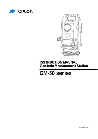
![i
HOW TO READ THIS MANUAL
Thank you for selecting the GM-50 series.
• Please read this Operator’s manual carefully, before using this product.
• GM has a function to output data to a connected host computer. Command operations from a host computer
can also be performed. For details, refer to "Communication manual" and ask your local dealer.
• The specifications and general appearance of the instrument are subject to change without prior notice and
without obligation by TOPCON CORPORATION and may differ from those appearing in this manual.
• The content of this manual is subject to change without notice.
• Some of the diagrams shown in this manual may be simplified for easier understanding.
• Always keep this manual in a convenient location and read it when necessary.
• This manual is protected by copyright and all rights are reserved by TOPCON CORPORATION.
• Except as permitted by Copyright law, this manual may not be copied, and no part of this manual may be
reproduced in any form or by any means.
• This manual may not be modified, adapted or otherwise used for the production of derivative works.
Symbols
The following conventions are used in this manual.
: Indicates precautions and important items which should be read before operations.
: Indicates the chapter title to refer to for additional information.
: Indicates supplementary explanation.
: Indicates an explanation for a particular term or operation.
[MEAS] etc. : Indicates Operation icons on the display and window dialog buttons.
{ESC} etc. : Indicates keys on the operation panel.
<Screen title> etc.: Indicates screen titles.
Notes regarding manual style
• Except where stated, “GM” means GM-50 series in this manual.
• Except where stated, instrument with display on both sides is used for illustration.
• Screens appearing in this manual are based on the setting "Dist. reso: 1 mm". When "Dist. reso: 0.1 mm" is
selected, the number of decimal places for distance and atmospheric condition input values will be increased
by one.
"33. CHANGING THE SETTINGS"
• Location of Operation icons in screens used in procedures is based on the factory setting. It is possible to
change the allocation of Operation icons.
"33. CHANGING THE SETTINGS"
• Learn basic operations in "4. PRODUCT OUTLINE" and "5. BASIC OPERATION" before you read each
measurement procedure. For selecting options and inputting figures, see "5.1 Basic Key Operation".
• Measurement procedures are based on continuous measurement. Some information about procedures when
other measurement options are selected can be found in “Note” ().
• KODAK is a registered trademark of Eastman Kodak Company.
• Bluetooth is a registered trademark of Bluetooth SIG, Inc.
• All other company and product names featured in this manual are trademarks or registered trademarks of
each respective organization.
Li-ion
S Li-ion
This is the mark of the Japan Surveying Instruments Manufacturers Association.](data:image/gif;base64,R0lGODlhAQABAIAAAAAAAP///yH5BAEAAAAALAAAAAABAAEAAAIBRAA7)