Electronic multi measuring instrument-me96 instruction manual dienhathe.vn
•
0 likes•155 views

Thiết Bị Điện Mitsubishi, Thiết Bị Điện, Điện Công Nghiệp Mitsubishi, Điện Công Nghiệp, Điện Hạ Thế Mitsubishi, Điện Hạ Thế, Điện Dân Dụng Mitsubishi, Điện Dân Dụng, Mitsubishi, Thiết Bị Đóng Cắt Mitsubishi, Thiết Bị Đóng Cắt, Thiết Bị Điện Mitsubishi, Thiết Bị Điện,

Recommended
Recommended
More Related Content
What's hot
What's hot (17)
Similar to Electronic multi measuring instrument-me96 instruction manual dienhathe.vn
Similar to Electronic multi measuring instrument-me96 instruction manual dienhathe.vn (20)
More from Dien Ha The
More from Dien Ha The (20)
Recently uploaded
Recently uploaded (20)
Electronic multi measuring instrument-me96 instruction manual dienhathe.vn
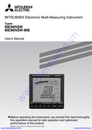
- 1. Types ME96NSR ME96NSR-MB User’s Manual Before operating the instrument, you should first read thoroughly this operation manual for safe operation and optimized performance of the product. Deliver this user’s manual to the end user. MITSUBISHI Electronic Multi-Measuring Instrument www.dienhathe.vn www.dienhathe.xyzwww.tailieukythuat.info
- 2. 2 Check the following as soon as you receive Mitsubishi Electronic Multi-Measureing Instru- ment : ● The package is in good condition. ● The product has not been damaged during transit. ● The product corresponds to your order specifications. ● This product has the following accessories. User’s Manual (Simplified) Attachment lug (with screw) Parts name 2 SpecificationsQuantity 1 A3 size Check on Your Delivery This product has the following optional plug-in module. It is possible to correspond to various I/O by installing the optional plug-in module. About the Optional Plug-in Module Sold Separately ME-4201-NS96 ME-0052-NS96 (✽2) ME-0040C-NS96 Type name of optional plug-in modules Pulse output 2 points – – Analog output 4 circuits – – I/O specifications Digital input – 5 points 4 points Digital output (✽1) 1 point 2 points – Communication – – CC-Link ✽1: The digital output of the ME-4201-NS96 is the alarm output of upper/lower limit. The digital outputs of the ME-0052-NS96 are opened or closed the contacts by the 16bit set register of the ModBus. ✽2: The ME-0052-NS96 is only combined with the type of ME96NSR-MB. In this manual, when the optional plug-in module is installed, it explains. www.dienhathe.vn www.dienhathe.xyzwww.tailieukythuat.info
- 3. 3 Contents Check on Your Delivery .......................................................................................................................................... 2 About the Optional Plug-in Module Sold Separately .............................................................................................. 2 Contents ................................................................................................................................................................... 3 Safety Precaution ..................................................................................................................................................... 4 EMC Directive Instruction ...................................................................................................................................... 6 1. Features ............................................................................................................................................................... 7 2. Display and Key Functions ................................................................................................................................. 8 3. Function Modes ................................................................................................................................................ 10 4. Set-up 4.1 Set-up Diagram ........................................................................................................................................... 12 4.2 Menu 1: Basic Set-up .................................................................................................................................. 14 4.3 Menu 2: Communication, Cancel of Digital Input Set-up .......................................................................... 17 4.4 Menu 3: Bar Graph Set-up .......................................................................................................................... 19 4.5 Menu 4: Display of Each Measurement, etc. Set-up .................................................................................. 20 4.6 Menu 5: Alarm Set-up................................................................................................................................. 22 4.7 Menu 6: Analog Output Set-up ................................................................................................................... 24 4.8 Menu 7: Pulse Output Set-up ...................................................................................................................... 26 4.9 Simplified Set-up ........................................................................................................................................ 28 5. Output Adjustment and How to Test 5.1 Analog Output Adjustment ......................................................................................................................... 32 5.2 Alarm Output Test ....................................................................................................................................... 33 5.3 Analog Output Test ..................................................................................................................................... 34 5.4 Pulse Output Test ........................................................................................................................................ 35 5.5 Digital Output Test ...................................................................................................................................... 36 6. Operation 6.1 Display Change ........................................................................................................................................... 37 6.2 Phase Change .............................................................................................................................................. 37 6.3 Bar Graph Display ...................................................................................................................................... 38 6.4 Maximum Value and Minimum Value Display ........................................................................................... 39 6.5 Cyclic Display Change ............................................................................................................................... 40 6.6 Alarm Display and How to Cancel ............................................................................................................. 41 6.7 Harmonics Display ..................................................................................................................................... 42 6.8 Expanded Counting Display ....................................................................................................................... 43 6.9 Display of Digital Input and Digital Output ............................................................................................... 44 6.10 Set Value Confirmation Mode ................................................................................................................... 44 7. Others 7.1 How to Rearrange the Display Pattern (P00) .............................................................................................. 45 7.2 Display the Type of the Optional Plug-in Module ...................................................................................... 47 7.3 Judgment Phase of Alarm Element ............................................................................................................. 47 7.4 Display Pattern Contents............................................................................................................................. 48 7.5 Maximum Scale Value ................................................................................................................................ 50 7.6 Maximum Scale Table ................................................................................................................................ 51 7.7 Measurement Characteristic ....................................................................................................................... 53 7.8 Troubleshooting .......................................................................................................................................... 54 ■ After Service ........................................................................................................................................... 54 1. Dimensions ........................................................................................................................................................ 55 2. Mounting ........................................................................................................................................................... 57 3. Wiring ................................................................................................................................................................ 58 4. Wiring Diagram ................................................................................................................................................. 60 Specifications ........................................................................................................................................................ 64 Communication Specifications .............................................................................................................................. 65 Set-up Table ........................................................................................................................................................... 66 Example of Simple Set-up ..................................................................................................................................... 67 Operation Installation Specification Example of Simple Set-up www.dienhathe.vn www.dienhathe.xyzwww.tailieukythuat.info
- 4. 4 Safety Precaution (Always read these instructions before using this equipment) For personnel and product safety, please read the contents of these operating instructions carefully before using. Please store this manual to make it accessible when required and always forward it to the end user. Indicates that incorrect handling may cause hazardous conditions. Always follow the instructions because they are important to personal safety. Otherwise, it could result in electric shock, fire, erroneous operation, and damage of the instrument. ■Normal Service Conditions CAUTION Conditions Below 600V, or 600A power lines Other power lines Length 30cm or more 60cm or more CAUTION Use the instrument in an environment that meets the normal service conditions as following points: ● Ambient temperature: -5 to 50°C, average day temperature exceeds 35°C ● Humidity: 30 to 85%RH, non condensing. ● Altitude: 1000m or less ● Pollution Degree: 2 ● Atmosphere without corrosive gas, dust, salt, oil mist. ● A place without excessive shocks or vibration. ● Do not expose to rain and water drips. ● Do not expose to direct sunlight. ● An area in where no pieces of metal and an inductive substance disperse. ● Do not expose to strong electromagnetic field and ambient noises. CAUTION ● This instrument should be installed and used by a qualified electrician. ● The instrument must not be powered and used until its definitive assembly on the cabinet’s door. ● Verify the following points; ٗ Auxiliary power supply and measuring ratings ٗ Current circuits, C1, C2 and C3 are Measurement category 1. ٗ Voltage circuits, P1, P2 and P3 are Measurement category 3. ● The instrument is to be mounted on a panel. All connections must be kept inside the cabinet. ● Tighten the terminal screws with the specified torque and use the suitable pressure connectors and suitable wire size. (see page 58) ● When wiring the instrument, be sure that it is done correctly by checking the instrument’s wiring diagrams. (see page 60 to 63) ● Be sure there are no foreign substances such as sawdust or wiring debris inside the instrument. ● Do not drop this instrument from high place. If you drop it and the display is cracked, do not touch the liquid crystal or get it in your mouth. If the liquid crystal is touched, wash it away at once. ● In order to prevent invasion of noise, do not bunch the control wires or communication cables with the main circuit or power wire, or install them close to each other. The distance between communicational signal lines, input signal lines and power lines, high voltage lines running parallel to each other are shown below. ■Installation Instructions Auxiliary power supply 100-240V AC+10-15%(50-60Hz) 8VA 100-240V DC+10-30% 5W Ratings Voltage Current Frequency 277V AC phase-neutral / 480V AC phase-phase 5A (via current transformer) 50/60Hz www.dienhathe.vn www.dienhathe.xyzwww.tailieukythuat.info
- 5. 5 ● Wipe dirt off the surface with a soft dry cloth. ● Check the following points. (at the cycle of six months to one year) ٗ Condition of the appearance ٗ Condition of the display ٗ Unusual sound, a smell, and generation of heat ٗ Condition of the wiring and the attachment ■Storage Conditions ● Ambient temperature the: -20 to 60°C, average day temperature exceeds 35°C ● Humidity range 30 to 85%RH, non condensing. ● Atmosphere without corrosive gas, dust, salt, oil mist. ● A place without excessive shocks or vibration. ● Do not expose to rain and water drips. ● Do not expose to direct sunlight. ● An area in where are pieces of metal and an inductive substance disperse. ■Disposal ● When disposing of this product, treat it as industrial waste. ● Battery is not used for this product. ■Guarantee The period of guarantee is earlier date of either 18 months from the manufacture date or 1 year from the sale date, except in the case that the failure has been caused by bad handling of the product, provided that it has been installed according to the manufacture’s instructions. ■Operation Instructions CAUTION ● When the external terminals are connected to the external equipments, the instrument and the exter- nal equipments must not be powered and used until its definitive assembly on the cabinet’s door. ● The rating of the terminal of the external equipment should satisfy the rating of the external terminal of this instrument. (See Specifications.) ■Maintenance Instructions CAUTION ● Do not touch the terminals while all the circuits connected to this instrument are alive. ● Do not disassemble or modify the instrument. ● Do not contact a chemical dust cloth to the instrument for a long time, or do not wipe it with benzene, thinner, alcohol. Safety Precaution www.dienhathe.vn www.dienhathe.xyzwww.tailieukythuat.info
- 6. 6 This section summarizes the precautions on conformance to the EMC Directive of the cabinet con- structed using this instrument. However, the method of conformance to the EMC Directive and the judgment on whether or not the cabinet con- forms to the EMC Directive has to be determined finally by the manufacturer. 1. EMC Standards The standards applicable to the EMC Directive ( No.89/336/EEC ) are listed below. (1) Radiated radio frequency emission -----------------------------------EN61000-6-4/2001 (2) Radiated radio frequency electromagnetic field immunity ------EN61000-6-2/2001 2. Installation (EMC directive) The instrument is to be mounted on panel of a cabinet. Therefore, the construction of a cabinet is important not only for safety but also for EMC. The instrument is examined by the following conditions. ● Conductive cabinet is used. ● Six faces of a cabinet have to be ensured conductivity for each other. ● A cabinet has to be connected to earth by a thick wire of low impedance. ● Holes on faces of cabinet have to be 10 cm or less in diameter. ● The terminals for protective earth and functional earth have to be connected to earth by a thick wire of low impedance. (A terminal for protective earth is important not only for safety but also for EMC.) ● All connections must be kept inside the cabinet. ● Wirings outside the cabinet have to be used with the shielded cable. The following diagram shows how to provide good contact of the shielded cable. ٗ Remove part of the outer cover. ٗ Remove part of the paint musk on the cabinet. ٗ Connect those parts with the clamp. Protective earth: Maintains the safety of the instrument and improves the noise resistance. Functional earth: Improves the noise resistance. Shield section Paint mask Shielded cable Screw Clamp fitting EMC Directive Instruction FG www.dienhathe.vn www.dienhathe.xyzwww.tailieukythuat.info
- 7. 7 This instrument measures the load status by inputting the secondary side of the VT and CT, and displays various measurement values. In addition, telemonitoring can be done by a variegated output function. ■Various Measurement Parameters ■Element simultaneous display of four measurements by large-scale bar graph and digital three-stage display. With the combination of bar graph and digital three-stage display, four measurement items can be displayed at the same time. Main measurements (A, V, W, PF) of the incoming panel can be displayed at the same time. And AAVG, A1, A2 and A3 can be displayed at the same time, also. ■Higher dimension measurement monitoring function by measurementASIC of original our company. Measuring elements are current, voltage, active power, reactive power, apparent power, power factor and frequency. In addition, it can measure harmonics and count active energy (imported, exported) and reactive energy (imported lag, imported lead, exported lag, exported lead). ■Conformity with the CE Marking standards. This instrument conform with the EMC standard (EN61326-1:2006) and the LVD standard (EN61010- 1:2001). ■Small & Flexible. Its dimension is 96×96mm of DIN size, the depth is 86mm, smaller than the previous model. And, it does not need the onerous specification of phase wire system when it is ordered because three phase 3- wire or the three phase 4-wire can be set in the set up mode. In addition, because the output option can be installed later, it is possible to hold down initial investment to a phased system expansion plan. ■Remote Input/Output Functions. It can expand the remote input/output functions to the ModBus communication. It can observe the state of five digital inputs and control two digital outputs with the electric power monitor. And, because the latch function is provided in the remote digital input and the pulse signal of 30ms or more can be maintained, it is possible to use it as an input monitor of the OCR alarm of ACB. ■Test Functions. It can make sure the check of wiring and the check of monitor program of system with the test functions of analog outputs, pulse outputs, alarm outputs and reply of communication data if there is no measurement input at the start-up of the equipment. 1. Features Refer to the followings in this manual. Average value: AVG Total RMS : Σ As for voltage, the phase to phase is described “L-L”, the phase to neutral is described “L-N”. ex) Average value of current : AAVG Three phase active power : ΣW ex) Phase 1 to phase 2 voltage: V12 Phase 1 to neutral voltage : V1N Current Current demand Voltage Active power Reactive power Apparent power Power factor Frequency Active energy Reactive energy Harmonic current Harmonic voltage Three phase 4-wire A1, A2, A3, AN, AAVG DA1, DA2, DA3, DAN, DAAVG V12, V23, V31, VLLAVG or V1N, V2N, V3N, VLNAVG ΣW, W1, W2, W3 Σvar, var1, var2, var3 ΣVA, VA1, VA2, VA3 ΣPF, PF1, PF2, PF3 HI1, HI2, HI3, HIN HV1N, HV2N, HV3N Hz Imported, Exported Imported lag, Imported lead, Exported lag, Exported lead THD, h1, h3, h5, h7, h9, h11, h13 (RMS, Distortion ratio) THD, h1, h3, h5, h7, h9, h11, h13 (RMS, Distortion ratio) Three phase 3-wire A1, A2, A3, AAVG DA1, DA2, DA3, DAAVG V12, V23, V31, VLLAVG ΣW Σvar – ΣPF HI1, HI2, HI3 HV12, HV23 A DA V W var VA PF Hz Wh varh HI HV Phase wire system www.dienhathe.vn www.dienhathe.xyzwww.tailieukythuat.info
- 8. 8 LEAD status LAG status Scale of the bar graph Outside range Alarm indicator Bar graph status Phase status Unit Metering status Harmonics Communication status Alarm status Test status Setup status Digital They show direction of Power Factor or Reactive Power on bar graph. They show the type of counting of Reactive Energy on Reactive Energy Display. They show the scales of the bar graph. Measurement value is outside range of scale of the bar graph. It shows the setting value of the upper limit or lower limit. They show the item expressed with the bar graph. They show the phase for each of the digital displays. They show the unit for each of the digital displays. When it is blinking, the instrument is counting active energy. It means that the digital displays are harmonics values. It shows that the instrument is equipped with a communication function. It blinks under the condition of a communication error. They show that the upper limit value or lower limit value was exceeded. It shows that the output of the option module is tested. It appears at Set-up mode. The measured value is displayed in a digital number. 1 2 3 4 5 6 7 8 9 10 11 12 13 14 15 14 1 2 13 12 11 10 9 8 5 4 3 4 6 7 15 ■Display Note: The above display is an example for explanation. 2. Display and Key Functions www.dienhathe.vn www.dienhathe.xyzwww.tailieukythuat.info
- 9. 9 ✽1: Each the phase cyclic and the display cyclic are stopped. ✽2: It is available only that displayed element in the displayed Wh, varh. ✽3: The last digit is fast-forwarded for 4 step per second. ✽4: The one step up digit from the last one is fast-forwarded for 4 step per second. It is available only the set of the ModBus address and the set of CC-Link station number. SET RESET MAX/MIN PHASE DISPLAY Set key Reset key +/– key Maximum/ Minimum key Phase change key Display change key ■Functions of operation key The operation key have various functions according to how they are pressed down. Meaning of code : (press), (press on over 1 second), (press on over 2 seconds), (press simultaneously) While the back light is off, if the operation key is pressed, the back light is always lit. If the operation button is pressed once again, the function in the above table appears. Note: SET – + RESET Key PHASEMAX/MIN DISPLAY Display changes. Phase changes. Mode changes to the max./min. display and the instantaneous display. An alarm condition is canceled. The item expressed with the bar graph is changed. Stop the auto cyclical change. (✽1) Harmonics number changes at harmonics display. The displays changes cyclically. The phases changes cyclically. All alarm conditions are canceled. The latching data of digital input on the display is canceled. The max./min. values on the display are reset to the instantaneous values. All of the max./min. values are reset to the present values. All of the counting values are zero reset. The display of set-up mode appears. The display of set value confirmation mode appears. The setup contents that is blinking is saved. The setup contents is changed to next content. The display of set-up menu appears. (At the final contents of the setup.) The End display appears. (At the final contents of the setup in the simplified set-up menu.) After the setup contents are saved, the display on operation mode appears if it is the End display. After the setup contents are not saved, the display on operation mode appears if it is the CANCEL display. The display of set-up menu appears. The End display appears. (In the simplified set-up menu.) The values of set-up and number of the menu are changed. (If it presses for 1 sec or more fast forward or fast return.)(✽3) The CANCEL display appears at the End display. Back to the previous contents. (The setup contents are saved.) The display of set-up menu appears. (At the start setup contents, and at the display of the option module.) The End display appears. (At the start setup contents in the simplified set-up mode.) The values of set-up and number of the menu are changed. Then it is carry up and fast forward or fast return. (✽4) Change the display of simplified set-up menu, and move to the start. (The setup contents are saved.) The display of simplified set-up mode appears. (At blinking the “End” in the set-up mode.) The type of the option module appears. (At blinking the “End” in the set-up mode.) The instrument is initialized. (At the CANCEL display.) Function Operation Mode OperationmodeSet-upmode/ SetvalueconfirmationmodeBasicSpecial The counting values of 3 digits of low lank are displayed. After pressing once again, the display returns. (✽2) 2. Display and Key Functions ● If the function of “maximum value and minimum value reset” and “Wh, varh zero reset” are done, data will be lost. Before the operation, please record data. ● If the function of “initializing of instrument” is done, the entire measurement (measurement display, alarm, analog output, pulse) stops. Notes www.dienhathe.vn www.dienhathe.xyzwww.tailieukythuat.info
- 10. 10 Alarm Output Test Analog Output Test Pulse Output Test Digital Output Test Set-up Menu 1 Set-up Menu 2 Set-up Menu 3 Set-up Menu 4 Set-up Menu 5 Set-up Menu 6 Set-up Menu 7 Set-up Menu 8 Simplified set-up Menu Set-up Menu 1 Set-up Menu 2 Set-up Menu 3 Set-up Menu 4 Set-up Menu 5 Set-up Menu 6 Set-up Menu 7 Set-up mode Set value confirmation mode Operation mode Test mode Set-up Menu 8 Instantaneous value cyclic display change Maximum value and minimum value cyclic display change Instantaneous value display Maximum value and minimum value display Instantaneous value cyclic phase change Maximum value and minimum value cyclic phase change ■Diagram of Each Mode This meter has 4 kinds of function modes. Use it at each mode according to your requirements. Note: Shaded set menus of the set value confirmation mode are only for confirming set values, and their settings cannot be changed. 3. Function Modes www.dienhathe.vn www.dienhathe.xyzwww.tailieukythuat.info
- 11. 11 ■Outline of Function Mode Operation mode Measuring and displaying in this mode. Instantaneous value display The instantaneous values of the set-up display pattern are displayed. Usually, this display is used. Maximum value and minimum value display The maximum values and minimum values are displayed. (see page 39) Instantaneous value cyclic display change Instantaneous value displays are automatically changed every 5 seconds. (see page 40) Instantaneous value cyclic phase change Instantaneous value phases are automatically changed every 5 seconds. (see page 40) Maximum value and minimum value cyclic display change Maximum value and minimum value displays are automatically changed every 5 seconds. (see page 40) Maximum value and minimum value cyclic phase change Maximum value and minimum value phases are automatically changed every 5 seconds. (see page 40) Set-up mode In this mode, all the setting items including primary voltage, primary current, and so forth can be set. Set necessary items before operation. (see pages 12 to 31) Set value confirmation mode This mode is for checking the contents of the set-up items. In this mode, the contents of the all set-up items are protected from changing accidentally. (see page 44) Test mode In this mode, the output function can be tested, when the option module is installed. A mock output can be put out even if only it supplies power to the instrument, and there is no input. This mode is independent of other modes. (see page 33 to 36) 3. Function Modes www.dienhathe.vn www.dienhathe.xyzwww.tailieukythuat.info
- 12. 12 4.1 Set-up Diagram 4. Set-up Phase wire Display pattern Using VT/ direct input Direct voltage Secondary voltage Primary voltage Secondary current Primary current Time constant for current demand Phase wire Display pattern Using VT/ direct input Direct voltage Secondary voltage Primary voltage Primary current Time constant for current demand CC-Link station number Communication method ModBus address ModBus baud rates ModBus parity ModBus stop bit CC-Link baud rates Communication module reset Communication method ModBus address ModBus baud rates ModBus parity ModBus stop bit CC-Link baud rates Communication module reset Digital input reset Operation mode Measurement display Set-up menu “End” End display Type of option display P-1 P-2 CANCEL display Example of set-up mode Set-up menu 1 Set-up menu 2 Simplifiedset-upmenu blink extinction CC-Link station number Initializing processShift automatically (Example) Example of set value confirmation mode For correct measurement, it is necessary to set the primary voltage and the primary current, etc. in the set-up mode. It can set necessary items, after it shifts from the Operation mode to set-up mode. Items are not set is the initial setting. In the case of normal use, it can use only by the set-up menu 1 (basic set-up). In the case to use the communication function, set the set-up menu 2. Refer to the next page or later for the set-up items. CAUTION 1. Make sure to set for Direct volt- age, Secondary voltage, Pri- mary voltage, Secondary cur- rent, Primary current. (Or check the set-up contents.) A correct measurement cannot be done if the set-up contents are wrong. 2. Set for the other set-up contents when it is necessary. When it is not done, it operates with the initial contents (refer to page 66). www.dienhathe.vn www.dienhathe.xyzwww.tailieukythuat.info
- 13. 13 4.1 Set-up Diagram 4. Set-up Shift from the operation mode to the set-up mode. Press them simultaneously for 2 seconds. Press them simultaneously for 1 second. Press them simultaneously for 1 second. Shift from the operation mode to the set value confirmation mode. Select the menu number to set or “End”. Get into each setting screen. Shift to the next setting item. Go back to the previous setting item. Memorize the setting contents, and go back to the operation mode. Skip remaining setting items during setting. Shift from the set-up mode to simplified set-up menu. Change the page of the simplified set-up menu. Expanded counting Harmonics Digital input/output Back light ON/OFF Current display digit Voltage display digit Active power display digit Reactive power display digit Apparent power display digit Current maximum scale Active power maximum scale Reactive power maximum scale Power factor scale Analog output 1 Analog output 2 Analog output 3 Analog output 4 Analog output limit Alarm item Alarm value Alarm delay time Action Select a set value. Shift to the End screen. Select “CANCEL”. Cancel the setting. Display the type of option unit. Initializing of instrument Key operation Press it for 2 seconds. Press it several times. Press it. Press it. Press it several times. Press it. Press it. Press it. Press it. Press it for 1 second. Press it. or or or Omitted in figure Arrow in figure + + + Set-up mode or set value confirmation mode Set-up menu 3 Set-up menu 4 Analog output 1 Adj. Analog output 2 Adj. Analog output 3 Adj. Analog output 4 Adj. Pulse output 1 Pulse width Set-up menu 5 Set-up menu 6 Set-up menu 8Set-up menu 7 Pulse output 2 ✽This figure writes all set menus. There is a menu not displayed by the presence of the setting condition and the option. Alarm cancel method + − + − SET SET SET SET SET SET SET RESET PHASE DISPLAY DISPLAY PHASE PHASE MAX/MIN + − 1 Press the key and the key simultaneously for 2 seconds to get in the set-up mode. 2 Select a set-up menu number by or key. 3 Change the contents in each set-up menu. (Refer to pages 14 to 27.) 4 After completion of set-up, select ‘End’ in the set-up menu and press the key. 5 When the End display appears, press the key once again. • How to Access the Set-up Items. + – SET RESET SET SET www.dienhathe.vn www.dienhathe.xyzwww.tailieukythuat.info
- 14. 14 4. Set-up 4.2 Basic Set-up Set-up Menu 1 Set-up menu 1 Phase wire 2 Display pattern 3 Using VT/ direct input DISPLAY SET DISPLAY SET DISPLAY SET DISPLAY SET Set the set-up menu number to “1”. (Set as shown in the right display.) Three phase 3-wire (2CT) Three phase 3-wire (3CT) Three phase 4-wire 3P3.2Ct 3P3.3Ct 3P4 : : : Initial content Three phase 3-wire : using VT Three phase 4-wire : direct input 2 Set the display pattern. (Initial content: P13) Note: As for detailed display patterns, refer to pages 48, 49. K: Display is made at this display setting. ᭝: Set by the set-up menu 4. (page 20 to 21) M: Select “P00”, and set display sequence and display position. (page 45 to 46) DA: current demand, HI: harmonic current, HV: harmonic voltage, DI: digital input, DO: digital output (DI/DO: only when option module is installed) VA: Three phase 4-wire only P01 P02 P03 P04 P05 P06 P07 P08 P09 P10 P11 P12 P13 P00 A DA V W PF var Hz varhVA Wh HI HV DI Wh Exported active energy DO Display pattern 4 Direct voltage DISPLAY SET 4 Set-up the rated voltage for scaling of the bar graph. If you set “YES” on set-up No.3, this display does not appear. 110V/63.5V 173V/100V 190V/110V 380V/220V 415V/240V 440V/254V 480V/277V 110V 220V Three phase 4-wire (phase to phase(L-L)/phase to neutral(L-N)) Three phase 3-wire (phase to phase(L-L)) + –, + –, + –, + –, + –, 1 Set the phase wire system. 3 Set-up the using VT or direct input (without VT). YES no : using VT : direct input varh Special In this set-up menu 1, set-up the basic contents as following for correct measurement . In the operation mode, after pressing the SET and the RESET simultaneously for 2 seconds or more, the following operation becomes available. An underline shows the initial value. www.dienhathe.vn www.dienhathe.xyzwww.tailieukythuat.info
- 15. 15 4. Set-up 4.2 Basic Set-up Set-up Menu 1 6 VT primary voltage 7 CT secondary current 6 Set the primary voltage value of VT in the case of using VT. If you set “no” on set-up No.3, this display does not appear. Initial value Three phase 3-wire : 10000V Three phase 4-wire : 200V 7 Set the secondary current value of CT. DISPLAY SET DISPLAY SET 5 VT secondary voltage DISPLAY SET 5 Set the secondary voltage values of VT in case of using VT. If you set “no” on set-up No.3, this display does not appear. 63.5V 100V 110V 115V 120V SET DISPLAY 8 CT primary current 8 Set the primary current value of CT. (The initial value is 5A.) DISPLAY SET Three phase 4-wire 100V 110V 220V Three phase 3-wire 5A 1A + –, + –, SET DISPLAY + –, + –, • • • • ✽ • From top digit, select the value of the flickering digit by and . The setting digit can be moved to right by the SET . The setting digit can be moved to left by the DISPLAY . The number of settable digits is 3 digits. Setting is available in the range from 60V to 750kV. (750000V) If it is set to other range than 60V to 750kV, error display (E05) appears. At the moment of the error display, press the SET , and review the set value, and set it once again. When the SET is pressed at the most lower digit, the setting item goes to the next one. + – • • • • ✽ • From top digit, select the value of the flickering digit by and . The setting digit can be moved to right by the SET . The setting digit can be moved to left by the DISPLAY . The number of settable digits is significant 2 digits. Setting is available in the range from 5A to 30kA (30000A). If it is set to other range than 5A to 30kA, error display (E05) appears. At the moment of the error display, press the SET , and review the set value, and set it once again. When the SET is pressed at the most lower digit, the setting item goes to the next one. + – www.dienhathe.vn www.dienhathe.xyzwww.tailieukythuat.info
- 16. 16 9 Time constant for current demand Set-up menu According to the set-up diagram (page 13), save the changed contents or continue to the other set-up menu. 9 Set up the time constant for calculating current demand. SET + –, + –, 0 second 10 seconds 20 seconds 30 seconds 40 seconds 50 seconds 1 minute 2 minutes 3 minutes 4 minutes 5 minutes 6 minutes 7 minutes 8 minutes 9 minutes 10 minutes 15 minutes 20 minutes 25 minutes 30 minutes Note: Even when the display pattern not display the current demand, this screen appears. If the current demand is not necessary, press the SET as it is. In the case of use only by the Set-up Menu 1 (basic set-up), go to “5. Operation” in page 37. In the case to use additional functions, go to “Set-up Menus 2 to 8” in page 17 to 32. 4. Set-up Set-up Menu 14.2 Basic Set-up If the contents in the Set-up Menu 1 are changed, the maximum value, minimum value, demand value of related measurement items will reset. (However, all of the counting values are not reset.) Note www.dienhathe.vn www.dienhathe.xyzwww.tailieukythuat.info
- 17. 17 4. Set-up Set-up menu DISPLAY SET DISPLAY SET 1 Communication method Set the set-up menu number to “2”. (Set as shown in the right display.) 1 Set the “CC-Link” or “ModBus” as the communication method. This display appears only if the type of ME96NSR-MB has the type of ME-0040C-NS96 optional plug-in module. CC 485 : : 2 ModBus address 2 Set the ModBus address number. In the case of CC-Link, this display does not appear. Settable addresses: 1 to 255 3 ModBus baud rates 3 Set the ModBus baud rate. In the case of CC-Link, this display does not appear. 2400 bps 4800 bps 9600 bps 19.2 kbps 38.4 kbps Stop bit : 1 Stop bit : 2 + –, + –, 5 ModBus stop bit 5 Set the ModBus stop bit. In the case of CC-Link, this display does not appear. + –, SETDISPLAY SETDISPLAY SETDISPLAY SETDISPLAY 4 ModBus parity 4 Set the ModBus parity. In the case of CC-Link, this display does not appear. Settable parity: non odd EVEn Settable baud rate: + –, + –, + –, CC-Link ModBus Set-up Menu 24.3 Communication, Cancel of Digital Input Set-up In the operation mode, press the SET and the RESET simultaneously for 2 seconds or more, and the following operation becomes available. www.dienhathe.vn www.dienhathe.xyzwww.tailieukythuat.info
- 18. 18 DISPLAY SET 6 CC-Link station number 6 Set the CC-Link station number. In the case of ModBus, this display does not apper. Settable addresses: 1 to 64 8 Communication module reset 8 Set the communication module reset. In the case of ModBus, this display does not apper. DISPLAY SET 7 CC-Link baud rates 7 Set the CC-Link baud rates. In the case of ModBus, this display does not apper. Settable baud rates: Set it ON. onoFF Note: When it is not set to ON, changed station number and baud rate do not become valid. 9 Digital input reset 9 Set the digital input(DI) reset method. Without digital input, this display does not apper. DISPLAY SET HoLd: Manual methodAuto: Automatic method Note: When selected the manual method(HoLd), input state is kept until the cancel operation by the hand. For the method of the cancel operation, refer to page 44. SET 0: 156k 1: 625k 2: 2.5M 3: 5M 4: 10M Set-up menu According to the set-up diagram (page 13), save the changed contents or continue to the other set-up menu. + –, + –, + –, + –, + –, 4. Set-up Set-up Menu 24.3 Communication, Cancel of Digital Input Set-up www.dienhathe.vn www.dienhathe.xyzwww.tailieukythuat.info
- 19. 19 4.4 Bar Graph Set-up Set-up Menu 3 4. Set-up Set-up menu DISPLAY SET DISPLAY SET DISPLAY SET DISPLAY SET DISPLAY SET 1 Current maximum scale 2 Active power maximum scale 3 Active power scale 4 Reactive power maximum scale The setting method is same as that of 2 maximum scale value of active power. Set-up menu SET According to the set-up diagram (page 13), save the changed contents or continue to the other set-up menu. 5 Power factor scale 5 Set the power factor scale. 00.5 + –, + –, + –, + –, + –, + –, + –, Set the set-up menu number to “3”. (Set as shown in the right display.) 1 Set the current maximum scale. The maximum scale is set in the range of about 40% to about 120% of the rated current. Note: This insturument’s rating is 100% value. The maximum scale value becomes the value in the table on page 50. 2 Set the maximum scale of Active power. The maximum scale is set in the range of about 40% to about 120% of the rated full load power. Note: This insturument’s rating is 100% value. The maximum scale value becomes the value in the table on page 50. 3 Set the single/double deflection of Active power. When the + and – are pressed, the scale value of bar graph flickers at single/double deflection. 4 Set the reactive power maximum scale. In the operation mode, press the SET and the RESET simultaneously for 2 seconds or more, and the following operation becomes available. 1. Accuray is defined to rated current. Although the maximum scale may display 120% or more of rated current and rated voltage in order to make a scale easy to read, current input is within 100% of rated current. 2. When the display pattern not to display power, reactive power, active energy and reactive energy is selected, the setting item related to them is skipped. Note www.dienhathe.vn www.dienhathe.xyzwww.tailieukythuat.info
- 20. 20 4 Set the back light auto off (Auto)/continuous on (HoLd). (Setting this is normally unnecessary.) If you set to ‘Auto off’, the back light turn off when there is no key operation for 5 minutes. When an operation key is pressed, it is lit for 5 minutes. At this moment, the display is not changed. When the operation key is pressed once again, the display is changed. Auto (Auto OFF) HoLd (Continuous ON) Set-up menu DISPLAY SET 1 Expanded counting 1 Set the combination of display for active energy and reactive energy. Combination of imported/exported and lag/lead can be selected. Combination 1 in the diagram is the standard use. Combination ! @ # $ Active energy (Wh) Reactive energy (varh) 2 Harmonics 3 Digital input/output 2 Set the harmonic measurement. on : Harmonic measurement value is displayed. off : Harmonic measurement value is not displayed. on : The state of the digital input/output is displayed. off : The state of the digital input/output is not displayed. DISPLAY SET DISPLAY SET DISPLAY SET DISPLAY SET 3 Set the display of the digital input/output state. When the ME-0052-NS96 or ME-0040C-NR96 type optional plug-in module is not installed, this menu cannot be set. + –, + –, + –, + –, + –, 4 Back light ON/OFF setting Set the set-up menu number to “4”. (Set as shown in the right display.) Imported Exported Imported lag (Exported) (lead) lag lead Imported lead (Exported) (lag) Imported lag lead Exported Display of combination ! Display of combination @ Display of combination # Display of combination $ 4. Set-up 4.5 Display of Each Measurement, etc. Set-up Set-up Menu 4 In the operation mode, press the SET and the RESET simultaneously for 2 seconds or more, and the following operation becomes available. www.dienhathe.vn www.dienhathe.xyzwww.tailieukythuat.info
- 21. 21 4. Set-up Set-up Menu 44.5 Display of Each Measurement, etc. Set-up 5 Current display digit 5 Set the current display digit. 888: 3 digits 8888: 4 digits DISPLAY SET 6 Voltage display digit 6 Set the voltage display digit. DISPLAY SET 7 Active power display digit 7 Set the active power display digit. DISPLAY SET 8 Reactive power display digit 8 Set the reactive power display digit. DISPLAY SET 9 Apparent power display digit 9 Set the apparent power display digit. SET Set-up menu According to the set-up diagram (page 13), save the changed contents or continue to the other set-up menu. + –, + –, + –, + –, + –, + –, Note: In No.t to No.o, the measurement element that doesn’t exist in the display pattern skips the setting. 888: 3 digits 8888: 4 digits 888: 3 digits 8888: 4 digits 888: 3 digits 8888: 4 digits 888: 3 digits 8888: 4 digits www.dienhathe.vn www.dienhathe.xyzwww.tailieukythuat.info
- 22. 22 Set-up menu DISPLAY SET DISPLAY SET 1 Alarm item 1 2 Alarm value 1 Set the set-up menu number to “5”. (Set as shown in the right display.) 1 Set the Alarm item to be allowed to measurement items. 2 Set the alarm value of Alarm item 1. The set-up range is as shown below. 3 Alarm item 2 to 4 3 Set the upper and lower limit alarm item 2 to 4 (AL2, AL3, AL4) in the same method. non A upper limit A lower limit Demand A upper limit Demand A lower limit V(L-L) upper limit V(L-L) lower limit W upper limit W lower limit var upper limit var lower limit PF upper limit PF lower limit Hz upper limit Hz lower limit Harmonic current total RMS value Harmonic voltage total distortion ratio non A upper limit A lower limit AN upper limit Demand A upper limit Demand A lower limit Demand AN upper limit V(L-N) upper limit V(L-N) lower limit V(L-L) upper limit V(L-L) lower limit W upper limit W lower limit var upper limit var lower limit PF upper limit PF lower limit Hz upper limit Hz lower limit Harmonic current total RMS value Harmonic current phase N RMS value Harmonic voltage total distortion ratio Display of non upper and lower limit alarm Display when A upper limit is set to upper and lower limit alarm DISPLAY SET Note 1: Even if it is a measurement item not selected by the display pattern, it is possible to select it. Note 2: The alarm of W, var, and PF is judged from the total RMS value. Note 3: The upper alarm of A and DA is judged from the phase of 1, 2, 3 and N. The lower alarm of A and DA is judged from the phase of 1, 2 and 3. (N is excluded.) Note 4: The alarm of the total distortion ratio is judged from the phase of 1, 2 and 3. (N is excluded.) DISPLAY SET + –, + –, + –, + –, Three phase 3-wire Three phase 4-wire Alarm item A, DA, AN, DAN upper limit A,DA lower limit V upper limit V lower limit W, var upper limit W, var lower limit PF upper limit PF lower limit Hz upper limit Hz lower limit Set-up range 5 to 100 to 120% 3 to 10 to 95% 25 to 110 to 135% 20 to 70 to 95% –95 to 100 to 135% –120 to 3 to 95% –0.05 to 1 to 0.05 –0.05 to –0.5 to 0.05 45 to 65Hz 45 to 65Hz 5 to 35 to 120% 0.5 to 3.5 to 20% Step 1% 1% 1% 1% 1% 1% 0.05 0.05 1Hz 1Hz 1% 0.5% Harmonic current RMS value upper limit Harmonic voltage total distortion ratio upper limit Note: An upper and lower limit alarm index by the bar graph is displayed in the step of about 5% though the digital value can be set in the above-mentioned step on A, DA, V, W and var. However, the alarm is generated with the accuracy of the digital value. DA: current demand V alarm value is set for value of primary voltage (direct voltage). A, DA, W and var is set for value of rated scale. to Example display when A upper limit is set to 100% 4. Set-up 4.6 Alarm Set-up Set-up Menu 5 This sets the upper and lower limit alarm. The upper and lower limit set value mark “ (blinking)” is displayed on the bar graph. From the display items, 4 element can be set. In the operation mode, press SET and RESET simultaneously for 2 seconds or more, and the following operation becomes available.www.dienhathe.vn www.dienhathe.xyzwww.tailieukythuat.info
- 23. 23 4. Set-up Set-up Menu 54.6 Alarm Set-up + –, + –, + –, Set-up menu According to the set-up diagram (page 13), save the changed contents or continue to the other set-up menu. 5 Alarm cancel method 4 Alarm delay time, delay time of max/min value 5 Set the alarm cancel method at occurrence of alarm. (screen, relay) Display of automatic reset method Display of manual reset method SET DISPLAY SET Method Automatic (Auto) Manual (HoLd) Cancel method When there is no alarm occurrence condition, alarm is automatically reset. 4 Set the alarm delay time. If the condition that the limit was exceeded continues more than the delay time, it will be in the alarm condition. And, if it dose not continue at this time, the max/min value is not updated. (see page 41) 0 seconds 5 seconds 10 seconds 20 seconds 30 seconds 40 seconds 50 seconds 1 minute 2 minutes 3 minutes 4 minutes 5 minutes Alarm is reset by pressing the RESET . Alarm continues until the RESET is pressed. www.dienhathe.vn www.dienhathe.xyzwww.tailieukythuat.info
- 24. 24 Set-up menu DISPLAY SET DISPLAY SET 1 Analog output CH1 measurement item 1 Set the measurement item for analog output CH1. Measurement element to be output is selected below. + –, + –, Three phase 3-wire non A1 A2 A3 AAVG:CH1 DA1 DA2 DA3 DAAVG V12 V23 V31 VLLAVG:CH2 ΣW:CH3 Σvar ΣPF:CH4 Hz HI1 HI2 HI3 HV12 HV23 Three phase 4-wire non A1 A2 A3 AN AAVG:CH1 DA1 DA2 DA3 DAN DAAVG V1N V2N V3N VLNAVG:CH2 V12 V23 V31 VLLAVG W1 W2 W3 ΣW:CH3 var1 var2 var3 Σvar VA1 VA2 VA3 ΣVA PF1 PF2 PF3 ΣPF:CH4 Hz HI1 HI2 HI3 HIN HV1N HV2N HV3N Set the set-up menu number to “6”. (Set as shown in the right display.) Note: DA: current demand HI: harmonics current total RMS value HV: harmonics voltage total distortion ratio 4. Set-up 4.7 Analog Output Set-up Set-up Menu 6 In the operation mode, press the SET and the RESET simultaneously for 2 seconds or more, and the following operation becomes available. Even if it is a measurement item from which it is not selected by the display pattern, the set up display can be displayed. When the ME-4201-NS96 type optional plug-in module is not installed, this menu cannot be set.www.dienhathe.vn www.dienhathe.xyzwww.tailieukythuat.info
- 25. 25 4. Set-up Set-up Menu 64.7 Analog Output Set-up to to DISPLAY SET 2 Analog output CH1 detailed set-up 2 Analog output detailed set-up (1) In the case when A, DA are set (6.1.1) • Current value is set to the maximum output value of analog output. It can set in the range of about 40% to about 120% of ratings. As for detailed set values, refer to page 51. (2) In the case when W, var are set • Power value and reactive power value are set to the maximum output value of analog output. (6.1.1) It can set in the range of about 20% to about 120% of ratings. As for detailed set values, refer to page 51. • In the case of W, set to the single/double deflection. (6.1.2) (initial content : single deflection) Note: As for output range, refer to page 53. + –, DISPLAY SET DISPLAY SET DISPLAY SET 3 Analog output CH2 to CH4 measurement item 4 Analog output CH2 to CH4 detailed set-up 3 Analog output CH2 to CH4 measurement item set-up Analog outputs CH2 to CH4 are set also in the same method as 1 analog output CH1 measurement item set-up. Analog outputs CH2 to CH4 are set also in the same manner as 2 analog output CH1 detailed set-up. 4 Analog output CH2 to CH4 detailed set-up Set if the undefined analog output is cut. 5 Analog output limit on : Cut the undefined analog output. oFF: Don’t cut the undefined analog output. 5 Set of the analog output limit. + –, + –, + –, Set-up menu According to the set-up diagram (page 13), save the changed contents or continue to the other set-up menu. + –, (3) In the case when PF is set The power factor value to the maximum output value of analog output CH1 is set from –0.5 to 1 to 0.5/–0 to 1 to 0 (4) In the case when Hz is set The frequency range of analog output is set. These settings can be set separately from measurement items. 60Hz 50Hz Note: When it is set to 50Hz, output is made at span 45 to 55Hz. When it is set to 60Hz, output is made at span 55 to 65Hz. 0 20 4 mA 1000W Single deflectionExample of power 1000W 20 4 12 mA 0–1000W 1000W Double deflection 20 4 12 mA 1–0.5 0.5 20 4 12 mA 10 0 to www.dienhathe.vn www.dienhathe.xyzwww.tailieukythuat.info
- 26. 26 Set-up menu DISPLAY SET 1 Pulse output item 1 1 Set the element to be output to pulse output 1. At initial, imported active energy is set to pulse output 1, accordingly, normally press the SET to go to the next setting. DISPLAY SET DISPLAY SET Example of pulse output 1 2 Pulse output item 1 pulse value 2 Set the pulse value of pulse output 1. Pulse value is selected from the table below, according to total load [kW]. Total load [kW] = ✽ Primary voltage value is calculated by phase to newtral. 1000 α × (Primary voltage) × (Primary current) α=3 (Three-phase 4-wire) α= 3 (Three-phase 3-wire) + –, + –, + –, 3 Pulse output item 2 + –, Example of pulse output 1 Example of pulse output 2 4 Pulse output item 2 pulse value + –, Set the set-up menu number to “7”. (Set as shown in the right display.) Pulse output element Imported active energy (Pulse output 1) Exported active energy Imported lag reactive energy (Pulse output 2) Imported lead reactive energy Exported lag reactive energy Exported lead reactive energy No output Display Wh – Wh varh (LAG) varh (LEAD) – varh (LAG) – varh (LEAD) non Settable elements DISPLAY SET DISPLAY SET 3 Set the element to be output to pulse output 2. Pulse output 2 is set also in the same method as q pulse output item 1 set-up. (At initial, imported lag reactive energy is set to pulse output 2.) In case of reactive energy, kW in the above table is exchanged into kvar, and kWh into kvarh. Total load [kW] 1 or higher and below 10 10 or higher and below 100 100 or higher and below 1000 1000 or higher and below 10000 10000 or higher and below 100000 100000 or higher Settable pulse value [kW/pulse] 1 10 100 1 10 100 0.1 1 10 0.1 1 10 0.01 0.1 1 0.01 0.1 1 0.001 0.01 0.1 0.001 0.01 0.1 kWh/Pulse kWh/Pulse kWh/Pulse MWh/Pulse MWh/Pulse MWh/Pulse 4 Set the pulse value of pulse output 2. Pulse output 2 is set also in the same method as w pulse output item 1 set-up. In the operation mode, press the SET and the RESET simultaneously for 2 seconds or more, and the following operation becomes available. When the ME-4201-NS96 type optional plug-in module is not installed, this menu cannot be set. 4. Set-up 4.8 Pulse Output Set-up Set-up Menu 7 www.dienhathe.vn www.dienhathe.xyzwww.tailieukythuat.info
- 27. 27 0.125s 0.500s 1.000s Note: When the pulse width is set to 0.500s, 1.000s, and pulse unit is set to multiplying factor ×1/100 time, when load is large, pulse output cannot follow, and the counting pulse may be decreased. SET Set-up menu According to the set-up diagram (page 13), save the changed contents or continue to the other set-up menu. 5 Pulse width 5 Set the pulse width of output pulse. + –, + –, 4. Set-up Set-up Menu 74.8 Pulse Output Set-up www.dienhathe.vn www.dienhathe.xyzwww.tailieukythuat.info
- 28. 28 No. q w e r Content Phase wire Display pattern Using VT/direct input Direct voltage No. t y u i Content VT secondary voltage VT primary voltage CT primary current Time constant for current demand Simplified setting page: P-1 No. o !0 !1 !2 Content Communication method ModBus address ModBus baud rates ModBus parity No. !3 !4 !5 !6 Content ModBus stop bit CC-Link station number CC-Link baud rates Communication module reset Simplified setting page: P-2 The setting contents of the main 16 items can be set by using two displays. It is set by the method of substituting the numerical value. For the setting contents, refer to the following table. 4. Set-up 4.9 Simplified Set-up + –, + –, + –, + –, Set-up menu DISPLAY DISPLAY DISPLAY SET DISPLAY SET DISPLAY SET DISPLAY SET 1 Phase wire Set the set-up menu number to “End”. (Set as shown in the right display.) Press the PHASE and the DISPLAY simultaneously for 1 second or more. 1 Set the phase wire. 1 : 3P3W 2CT 2 : 3P3W 3CT 3 : 3P4W 00 : P00 to 13 : P13 0 : direct input. 1 : using VT 2 Display pattern 2 Set the display pattern. 3 Using VT/ direct input 3 Set the using VT or direct input (without VT). + –, [3P3W] 1 : 110V 2 : 220V [3P4W] 1 : 63.5/100V 2 : 100/173V 3 : 110/190V 4 : 220/380V 5 : 240/415V 6 : 254/440V 7 : 277/480V 4 Direct voltage 4 Set the rated voltage for scaling for the bar graph. If you set “1: using VT” on set up No.3, this content cannot be set. PHASE + For 1 secend or more In the operation mode, press the SET and the RESET simultaneously for 2 seconds or more, and the following operation becomes available. By pressing PHASE key in the simplified set-up mode, the simplified setting page is changed. www.dienhathe.vn www.dienhathe.xyzwww.tailieukythuat.info
- 29. 29 4. Set-up 4.9 Simplified Set-up 5 VT secondary voltage 5 Set the secondary voltage values of VT in case of using VT. If you set “0: direct input” on set up No.e, this content cannot be set. + –, [3P3W] 1 : 100V 2 : 110V 3 : 220V [3P4W] 1 : 63.5V 2 : 100V 3 : 110V 4 : 115V 5 : 120V 6 VT primary voltage 6 Set the primary voltage values of VT in case of using VT. If you set “0: direct input” on set up No.e, this content cannot be set It is set by the top 3 digits voltage values and the exponent values (10 to the n-th power). The set-up order is the exponent values and the voltage values.+ –, Exponent values: 0 (100 = 1 time) 1 (101 = 10 times) 2 (102 = 100 times) 3 (103 = 1000 times) Voltage values: the top 3 digits (0 to 9) Example: Set-up to 10000V Exponent values: 2 Voltage values: 100 7 CT primary current 7 Set the primary current values of CT. It is set by the top 2 digits current values and the exponent values (10 to the (n-1)th power). The set-up order is the exponent values and the current values. + –, Exponent values: 0 (10-1 = 0.1 time) 1 (100 = 1 time) 2 (101 = 10 times) 3 (102 = 100 times) 4 (103 = 1000 times) Current values: the top 2 digits (0 to 9) Example: Set-up to 50A Exponent values: 1 Current values: 50 8 Time constant for current demand 8 Set the time constant for calculating current demand. + –, 00: 0s 01: 10s 02: 20s 03: 30s 04: 40s 05: 50s 06: 1min 07: 2min 08: 3min 09: 4min 10: 5min 11: 6min 12: 7min 13: 8min 14: 9min 15: 10min 16: 15min 17: 20min 18: 25min 19: 30min DISPLAY SET DISPLAY SET DISPLAY SET DISPLAY SET (Page change of set-up display) www.dienhathe.vn www.dienhathe.xyzwww.tailieukythuat.info
- 30. 30 4. Set-up 9 Communication method 9 Set the communication method. It is set only if the type of ME96NSR-MB has the CC-Link optional plug-in module. In the case of the other combination, this content cannot be set. + –, 1: CC-Link 2: ModBus !0 ModBus address !0 Set the ModBus address number. In the case of CC-Link, this content cannot be set. + –, Address: 001 to 255 DISPLAY SET !1 ModBus baud rates !1 Set the ModBus baud rate. In the case of CC-Link, this content cannot be set. + –, 1: 2400bps 2: 4800bps 3: 9600bps 4: 19.2kbps 5: 38.4kbps DISPLAY SET !2 ModBus parity !2 Set the ModBus parity. In the case of CC-Link, this content cannot be set. + –, 0: non 1: odd 2: even DISPLAY SET !3 ModBus stop bit !3 Set the ModBus stop bit. In the case of CC-Link, this content cannot be set. + –, 1: 1 2: 2 DISPLAY SET DISPLAY SET !4 CC-Link station number !4 Set the CC-Link station number. In the case of ModBus, this content cannot be set. + –, Address: 01 to 64 !5 CC-Link baud lates !5 Set the CC-Link baud rate. In the case of ModBus, this content cannot be set. + –, 1: 156kbps 2: 625kbps 3: 2.5Mbps 4: 5Mbps 5: 10Mbps DISPLAY SET DISPLAY SET Note: If it doesn’t have the communication function, contents on a simplified setting page P-2(No.o to !6) cannot be set. 4.9 Simplified Set-up www.dienhathe.vn www.dienhathe.xyzwww.tailieukythuat.info
- 31. 31 4.9 Simplified Set-up !6 Communication module reset + –, 0: OFF 1: ON Set-up menu qPhase wire 1:3P3W (2CT) 2:3P3W (3CT) 3:3P4W tVT secondary voltage [3P4W] 1:63.5V 2:100V 3:110V 4:115V 5:120V [3P3W] 1:100V 2:110V 3:220V !2ModBus parity 0:non 1:odd 2:EVEn wDisplay pattern 00:P00 11:P11 01:P01 12:P12 02:P02 13:P13 03:P03 04:P04 05:P05 06:P06 07:P07 08:P08 09:P09 10:P10 rDirect voltage [3P4W] 1:63.5V/110V 2:100V/173V 3:110V/190V 4:220V/380V 5:240V/415V 6:254V/440V 7:277V/480V [3P3W] 1:110V 2:220V eUsing VT /direct input 0:direct input 1:using VT oCommunication method 1:CC-Link 2:ModBus !1ModBus baud rates 1:2400bps 2:4800bps 3:9600bps 4:19.2kbps 5:38.4kbps !0ModBus address 001 to 255 According to the set-up diagram (page 13), save the changed contents or continue to the other set-up menu. + –, SET !3ModBus stop bit 1:1 2:2 !4CC-Link station number 01 to 64 !6Communication module reset 0:OFF 1:ON !5CC-Link Baud rates 1:156kbps 2:625kbps 3:2.5Mbps 4:5Mbps 5:10Mbps yVT primary voltage [Exponent value] 0:60 to 999V 1:1000 to 9990V 2:10000 to 99900V 3:100000 to 750000V [Voltage value] (100 digits) (10 digits) (1 digit) 0 to 9 0 to 9 0 to 9 uCT primary current [Exponent value] 0:5.0 to 9.9A 1:10 to 99A 2:100 to 990A 3:1000 to 9900A 4:10000 to 30000A [Current value] (10 digits) (1 digit) 0 to 9 0 to 9 iTime constant for current demand 00:0s 10:5min 01:10s 11:6min 02:20s 12:7min 03:30s 13:8min 04:40s 14:9min 05:50s 15:10min 06:1min 16:15min 07:2min 17:20min 08:3min 18:25min 09:4min 19:30min !6 Set the communication module reset. In the case of ModBus, this content cannot be set. Set it ON. ■Simplified Set-up contents list <Setting page: P-1> <Setting page: P-2> 4. Set-up www.dienhathe.vn www.dienhathe.xyzwww.tailieukythuat.info
- 32. 32 When the ME-4201-NS96 type optional plug-in module is installed, it is possible to adjust zero and span of analog output. (Only CH that sets the analog output can be done. ) Please adjust it only when the matches with the receiving instrument or the output have changed. In the operation mode, press the SET and the RESET simultaneously for 2 seconds or more, and the following operation becomes available. 5. Output Adjustment and How to Test 5.1 Analog Output Adjustment Set-up menu DISPLAY SET DISPLAY SET DISPLAY SET SET Set-up menu According to the set-up diagram (page 13), save the changed contents, or continue to the other set-up menu. 20mA 4 Zero adjustment ᭝mA INPUT INPUT INPUT 20mA 4 Span adjustment ᭝mA Single deflection 0 ᭝mA Double deflection 0 q Zero Adj. for CH1 w Span Adj. for CH1 CH2, CH3 and CH4 can be adjusted the same as above. q Set the zero adjustment for CH1. w Set the span adjustment for CH1. + –, + –, + –, + –, Set the set-up menu number to “8”. (Set as shown in the right display.) ±50 steps can be set. (about ±0.3mA ) ±50 steps can be set. (about ±0.3mA ) www.dienhathe.vn www.dienhathe.xyzwww.tailieukythuat.info
- 33. 33 When the ME-4201-NS96 type optional plug-in module is installed, simulated signal output to test the alarm output circuit can be put out. Operate it according to the following. The following operation becomes possible when you turn on the power supply while pressing the DISPLAY at the state of power failure. It is impossible to test without the option module. 5.2 Alarm Output Test q Test the alarm output. When the , is pressed, the display and the contact output are changed as following. + – Test menu q Alarm output test SET SET Set the test menu number to “1”. (Set as shown in the right display.) Test menu In case of test the other output, according to the 5.3 to 5.5, continue to the test. When the test is finished, turn off the power supply. + –, + –, + –, oFF (Opened) on (Closed) 5. Output Adjustment and How to Test www.dienhathe.vn www.dienhathe.xyzwww.tailieukythuat.info
- 34. 34 When the ME-4201-NS96 type optional plug-in module is installed, simulated signal output to test the analog output circuit can be put out. Operate it according to the following. The following operation becomes possible when you turn on the power supply while pressing the DISPLAY at the state of power failure. It is impossible to test without the option module. 5.3 Analog Output Test Test menu SET SET Set the test menu number to “2”. (Set as shown in the right display.) Test menu In case of test the other output, according to the 5.2 to 5.5, continue to the test. When the test is finished, turn off the power supply. q Analog output CH1 test w Analog output CH2 test + –, + –, + –, SET e Analog output CH3 test + –, SET SET r Analog output CH4 test + –, + –, q Test the analog output CH1. When the , is pressed, the display and the analog output CH1 are changed as following. + – 50%output 100%output0%output w Test the analog output CH2. When the , is pressed, the display and the analog output CH2 are changed as following. + – 50%output 100%output0%output e Test the analog output CH3. When the , is pressed, the display and the analog output CH3 are changed as following. + – 50%output 100%output0%output r Test the analog output CH4. When the , is pressed, the display and the analog output CH4 are changed as following. + – 50%output 100%output0%output 5. Output Adjustment and How to Test www.dienhathe.vn www.dienhathe.xyzwww.tailieukythuat.info
- 35. 35 When the ME-4201-NS96 type optional plug-in module is installed, simulated signal output to test the pulse output circuit can be put out. Operate it according to the following. The following operation becomes possible when you turn on the power supply while pressing the DISPLAY at the state of power failure. It is impossible to test without the optional plug-in module. 5.4 Pulse Output Test Test menu SET SET SET Set the test menu number to “3”. (Set as shown in the right display.) Test menu In case of test the other output, according to the 5.2 to 5.5, continue to the test. When the test is finished, turn off the power supply. + –, + –, q Pulse output CH1 test + –, w Pulse output CH2 test + –, q Test the pulse output CH1. When the , is pressed, the display and the pulse output are changed as following. + – oFF (Opened) on (Closed) q Test the pulse output CH2. When the , is pressed, the display and the pulse output are changed as following. + – oFF (Opened) on (Closed) 5. Output Adjustment and How to Test www.dienhathe.vn www.dienhathe.xyzwww.tailieukythuat.info
- 36. 36 When the ME-0052-NS96 type optional plug-in module is installed, simulated signal output to test the digital output circuit can be put out. Operate it according to the following. The following operation becomes possible when you turn on the power supply while pressing the DISPLAY at the state of power failure. It is impossible to test without the optional plug-in module. 5.5 Digital Output Test Test menu SET SET Set the test menu number to “4”. (Set as shown in the right display.) Test menu In case of test the other output, according to the 5.2 to 5.4, continue to the test. When the test is finished, turn off the power supply. + –, + –, q Digital output CH1 test + –, SET w Digital output CH2 test + –, Note: An initial value of each CH of this test mode is “Open”. If CH is changed or this test mode ends, the output becomes “Open” . q Test the digital output CH1. When the , is pressed, the display and the contact output are changed as following. + – oFF (Opened) on (Closed) w Test the digital output CH2. When the , is pressed, the display and the contact output are changed as following. + – oFF (Opened) on (Closed) 5. Output Adjustment and How to Test www.dienhathe.vn www.dienhathe.xyzwww.tailieukythuat.info
- 37. 37 6.1 Display Change 6.2 Phase Change 6. Operation By pressing DISPLAY , the measurement display will switch over. Example of display change (display pattern: P01) DISPLAY First display Second display Third display Fourth display Display number Note 1: When the display is changed by pressing DISPLAY , the following display is displayed just for a few seconds. Note 2: Even in the maximum and minimum value display, when the DISPLAY is pressed, the display will switched over. This shows the second display among the 4 display. DISPLAY DISPLAY DISPLAY Display items and sequences vary with display patterns (P01 to P13) and additional display. As for detailed display pattern, refer to page 48, 49. Reference By pressing PHASE , the current phase and the voltage phase will switch over. Example of display change Current average value Power (total) Voltage average value Current phase 1 Power (total) Voltage phase 1-2 Current phase 2 Power (total) Voltage phase 2-3 Current phase 3 Power (total) Voltage phase 3-1 Note 1: Even in the maximum and minimum value display, when PHASE is pressed, the phase will switch over. PHASE PHASE PHASE PHASE www.dienhathe.vn www.dienhathe.xyzwww.tailieukythuat.info
- 38. 38 6.3 Bar Graph Display AVG (or Σ) of display measurement element ΣPFΣvarΣWAAVGV (L-L) AVG Hz Example of display of upper stage element on bar graph Example of display of power factor on bar graph [Three-phase 4 wire] AVG (or Σ) of display measurement element ΣPFΣvarΣWAAVGV(L-L)AVGV (L-N) AVG Hz (ii) None of the above [Three-phase 3 wire] Upper Lower MiddleΣPFΣvarΣWAAVGV (L-L) AVG Hz [Three-phase 4 wire] Upper Lower MiddleΣPFΣvarΣWAAVGV (L-L) AVGV (L-N) AVG Hz 6. Operation Measurement item to be displayed on bar graph can be selected. By displaying others than the measurement items digitally displayed, 4 elements can be displayed at once. ● Explanation of bar graph In the bar graph, measurement elements shown by “ ” or “ ” are displayed. As for voltage, current, active power, reactive power, power factor, and frequency, they can be displayed on the bar graph even if they are not set to display pattern. ● Selection of bar graph Press + or – , to select measurement elements to be displayed on the bar graph. The display element in the bar graph changes as follows by the display pattern that has been selected. (i) When digital three-stage display are the same entire elements [Three-phase 3 wire] www.dienhathe.vn www.dienhathe.xyzwww.tailieukythuat.info
- 39. 39 6. Operation 6.4 Maximum Value and Minimum Value Display Instantaneous value display Maximum value and minimum value display MAX/MIN MAX/MIN Note 1: In the maximum value and minimum value display, bar graph is lit only between the maximum value and the minimum value. Note 2: When the screen shifts to the maximum value and minimum value display, the followings are displayed from head in the order below. A AN DA DAN V W var VA PF Hz HI HIN HV However, item that are not set for display are not displayed. Note 3: As for harmonic, only the following maximum values are displayed. Harmonic current total effective value, 1st, 3rd, 5th, 7th, 9th, 11th, 13th current effective values Harmonic voltage total distortion ratio, 1st voltage effective value, 3rd, 5th, 7th, 9th, 11th, 13th containing ratio Note 1: The maximum values and minimum values of being not displayed are not reset. Note 2: As for harmonic, all degrees are reset. RESET When RESET and + are pressed simultaneously for 2 seconds or more, all the maximum values and minimum values are reset. ● Delay time of max/min value If max/min value doesn’t continue for a long time since delay time, it doesn’t update it. (Delay time is set by set-up menu 5 “Alarm delay time, delay time of max/min value”.) Please set the delay time when you do not want to make the maximum value updated in the condition of becom- ing a value with excessive only way short time such as starting currents of the motor. Note 1: When delay time is set, the value whose value of middle stage is larger than the maximum value might be displayed until delay time passes. Note 2: A similar phenomenon might happen in the demand current, harmonics current, harmonics voltage. The maximum values and the minimum values are displayed. ● Display of maximum value and minimum value When MAX/MIN is pressed, the display is changed into the maximum value and minimum value display. And when MAX/MIN is pressed, the display changes back to the instantaneous value display. Display change example (display pattern : P01) ● Reset the maximum value and minimum value When RESET is pressed for 2 seconds or more, the displayed maximum value and minimum value can be reset. “Reset” means that maximum/minimum value turns into the save value as the instantaneous value. www.dienhathe.vn www.dienhathe.xyzwww.tailieukythuat.info
- 40. 40 6. Operation 6.5 Cyclic Display Change In cyclic display, display and phases automatically change every 5 seconds. ● Cyclic display change When DISPLAY is pressed for about 2 seconds, the cyclic display change appears. It is possible to cyclic display change it even on the maximum value and minimum value display. Display for 5 seconds Display for 5 seconds Display for 5 seconds Display for 5 seconds Press for 2 seconds. DISPLAY Note 1: Before shifting to the cyclic display change screen, the display blinking 3 times. Note 2: By pressing any other key than the SET , it goes back to manual change. Note 3: In the cyclic display change, drawing number is not displayed. ● Cyclic phase change When PHASE is pressed for about 2 seconds, the cyclic phase change appears. It is possible to cyclic phase change it even on the maximum value and minimum value display. Display for 5 seconds Display for 5 seconds Display for 5 seconds Press for 2 seconds. Note 1: Before shifting to the cyclic display change, the display blinking 3 times. Note 2: By pressing any other key than the SET , it goes back to manual change. Display for 5 seconds PHASE www.dienhathe.vn www.dienhathe.xyzwww.tailieukythuat.info
- 41. 41 6. Operation 6.6 Alarm Display and How to Cancel ● Set-up Refer to 4.6 Alarm Set-up. (see page 22) ● Alarm indicator If the item that had alarm set-up is displayed on the bar graph, the alarm indicator appears. By blinking of “ ”, upper or lower limit is shown. ● Display and Alarm output, How to cancel Alarm condition: If a measurement value exceeds an alarm value, the parts of display blink and an alarm relay contact closed. ● Alarm cancel How it cancels by ‘alarm cancel method’ is different. Alarm cancel method Measurement value > Upper limit value (or Measurement value < Lower limit value) Measurement value < Upper limit value (or Measurement value > Lower limit value) Normal display Normal display ClosedAlarm relay contact DisplayAutomatic (Auto) Manual (HoLd) Display Alarm relay contact Closed Closed Opened Opened Note 1: When the alarm condition, the digital value, the unit (A, V, W, var, VA, PF, Hz), and the phase (1, 2, 3, N, AVG, Σ, DM) of the measurement element are blinking. There is no blink when the element is not a display. Note 2: When the alarm hold condition, the unit (A, V, W, var, VA, PF, Hz), and the phase (1, 2, 3, N, AVG, Σ, DM) of the measurement element are blinking. There is no blink when the element is not a display. Note 3: Only ALARM , HI or LO blinks on the maximum value and minimum value display. Note 4: In the harmonics, only total distortion ratio and RMS value are blinking. The display of degree is not blinking. Note 5: The alarm is generated on all the following conditions. 1) The display pattern is set to “P00” 2) The setting displays only some phases of A (DA). 3) A (DA) is set to the alarm element. 4) The input of the phase not displayed exceeds the alarm setting value. ALARM , HI or LO : blink ALARM , HI or LO : blink ALARM , HI or LO : appear RESET ● Alarm delay time If the condition that the limit was exceeded continues more than the delay time, it will be in the alarm condition. The alarm output by rush current can be prevented. Automatic (Auto) Manual (HoLd) When the measurement value falls below the upper setting value or exceeds the lower setting value, alarm is automatically canceled. After the measurement value falls below the upper value or exceeds the lower setting value, alarm is maintained. When the element that generates the alarm is displayed, and the button is pressed, the alarm is canceled. When the button is pressed for two seconds or more, all elements of alarm are canceled in bulk. RESET RESET www.dienhathe.vn www.dienhathe.xyzwww.tailieukythuat.info
- 42. 42 6. Operation 6.7 Harmonics Display Harmonic RMS value and distortion ratio can be displayed. ● Measurement items Harmonic total 1st 3rd 5th 7th 9th 11th 13th Degree Distortion ratio RMS value Distortion ratio RMS value Current Voltage Note 1: Even when the RMS value of voltage harmonics is set to phase to phase voltage display, it is displayed in phase to neutral voltage. Note 2: When a fundamental harmonic is 0, the distortion ratio display 0%. ● Degree change method When + and – are pressed, harmonic degrees change. When PHASE is pressed, harmonic phases change. ● Harmonic display examples Note: Harmonic total is shown by “ALL”. Example of harmonic current total display( ) ( )Example of harmonic voltage 5th display PHASE PHASE PHASE PHASE PHASE PHASE PHASE PHASE PHASE PHASE PHASE PHASE Current total phase 1 Current 1st phase 1 Voltage total phase 1-N Voltage 1st phase 1-N Voltage 3rd phase 1-N Voltage 13th phase 1-N Current total phase N RMS Current 1st phase N RMS Current 3rd phase N RMS Current 13th phase N RMS Current total phase 2 Current total phase 3 Distortion ratio/RMS Current 1st phase 2 Current 1st phase 3 RMS Current 3rd phase 1 Current 3rd phase 2 Current 3rd phase 3 Distortion ratio/RMS Current 13th phase 1 Current 13th phase 2 Current 13th phase 3 Distortion ratio/RMS Voltage total phase 2-N Voltage total phase 3-N Distortion ratio/RMS Voltage 1st phase 2-N Voltage 1st phase 3-N RMS Voltage 3rd phase 2-N Voltage 3rd phase 3-N Distortion ratio/RMS Voltage 13th phase 2-N Voltage 13th phase 3-N Distortion ratio/RMS Harmonic current (phase N) Next display Harmonic current , Previous display Harmonic voltage PHASE PHASE PHASE PHASE PHASE PHASE PHASE PHASE PHASE PHASE PHASE PHASE DISPLAYDISPLAYDISPLAY DISPLAY + – ,+ – ,+ – ,+ – ,+ – ,+ – ,+ – ,+ – ,+ – www.dienhathe.vn www.dienhathe.xyzwww.tailieukythuat.info
- 43. 43 Measured value display and enlarged 3 digital figures display of active energy and reactive energy can be displayed. ● Active energy and reactive energy display Active energy and reactive energy are displayed on the lower stage. ● Enlarged 3 digital figures When + and – are pressed simultaneously for 2 seconds, values of active energy and reactive energy are enlarged by 3 figures. 6. Operation 6.8 Expanded Counting Display ● Wh and varh zero reset When SET , RESET and PHASE are pressed simultaneously for 2 seconds, the measured values of active energy (Wh) and reactive energy (varh) are reset. (This is effective only in the instantaneous value display.) Note 1: All of active energy (Wh) and reactive energy (varh) not displayed are reset too. Pressing simultaneously for 2 seconds + –, Note 1: This function is made only on active energy and reactive energy displayed. ● Example for display Exported active energy Exported lag reactive energyImported lead reactive energy Exported lead reactive energy ● 2 quadrants/4 quadrants counting (Reactive energy) In the reactive energy counting, the taking quadrant is 2 methods as follows. <4 quadrants counting> It is counting (Imported lag), (Exported lead), (Imported lead) and (Exported lag) respectively as division of one. In general, it is counted by this method. How- ever, at the boundary of each division, there is a dead region. It is suitable for the counting of equipment with the private electric generator. +var -var -W +W Exported lag Exported lead Imported lead Imported lag Exported lag Exported lead Imported lead Imported lag <2 quadrants counting> (Imported lag) and (Exported lead) are counted as divi- sion of one. (Imported lead) and (Exported lag) are counted as division of one. The dead region is made only nearby var=0 (power factor = 1). Therefore, because the dead region is not made nearby power factor = 0. It is suitable for the counting of equip- ment without the private electric generator and the reac- tive power of the capacitor load at the power factor = 0, generally. +var -var -W +W Exported lag Exported lead Imported lead Imported lag Exported lag Exported lead Imported lead Imported lag In the set of the expanded counting of the set-up menu 4.1, • 2 quadrants counting is selected in the combination ! and @. • 4 quadrants counting is selected in the combination # and $. Display type is as shown in the right table according to total load power. In the case of reactive power amount, kW in the above table is exchanged into kvar, and kWh into kvarh. Total load (kW) 1 to 10 10 to 100 100 to 1000 1000 to 10000 10000 to 100000 100000 or higher Digital display 8888.88 88888.8 888888 8888.88 88888.8 888888 Unit (k/M) k M Total load [kW] = 1000 α × (Primary voltage value) × (Primary current value) α = 3 Three-phase 4-wire type (Primary voltage value: phase to neutral) α = 3 Three-phase 3-wire type (Primary voltage value: phase to phase) www.dienhathe.vn www.dienhathe.xyzwww.tailieukythuat.info
- 44. 44 6.9 Display of Digital Input and Digital Output Display the digital input and digital output state. When the ME-0052-NS96 or ME-0040C-NS96 type optional plug-in module is not installed, this operation cannot be done. ● The display of the digital input and the digital output ● The reset method of the digital input The reset method of the digital input has the “Auto reset method” and the “Latch method”. When it is set the latch method, the input status is continued until the latch canceling operation. For example, when the alarm contact is input, if the alarm is stopped, you cannot miss the alarm happened because it is continued the happened status in this instrument. ● How to cancel the latch qIn the operation mode, by pressing DISPLAY , it is displayed the digital input (d.in) display. wAt the display of the digital input, the latch is canceled by pressing RESET for 2 seconds or more. Note: To display the digital input, it is needed to set “display of the digital input/output” to “on”. The initial content is set to “on”. 6.10 Set Value Confirmation Mode When you want to confirm the set value, you use the set value confirmation mode. In this mode, the contents of the set-up items cannot be set, which prevents changing other set values by mistake in operation. ● Change into set value confirmation mode In the operation mode, press SET for 2 seconds to get into the set value confirmation mode. ● Set value confirmation As same as in the set-up diagram (page 12), select the set-up menu number you want to confirm, and press the SET . By + and – select the set value. The way to get back to the operation mode is also same as in the set-up diagram. But it cannot confirm the simplified set-up menu in the set value confirmation mode. 6. Operation (Example of digital input display) (Example of digital output display) (Set-up mode) (Set value confirmation mode) blink extinction www.dienhathe.vn www.dienhathe.xyzwww.tailieukythuat.info
- 45. 45 7.1 How to Rearrange the Display Pattern (P00) 7. Others Even if there is no display pattern that you like in the display patterns P01 to P13, individual set-up is available by the display pattern P00. This set-up is made in the set-up menu 1. Explanation begins with the set “P00” in 2 display pattern of the setting menu 1 (page 14). (Others are omitted here, so refer to the setting menu 1.) ■ The number of settable display is up to 4 display. And the number of measurement elements to be dis- played is up to 12 items. ■ Explanation is made with the example of the following display pattern. ■ Setting method Screen 4-1 Upper stage: measurement item 1 Middle stage: measurement item 2 Lower stage: measurement item 3 DISPLAY DISPLAY DISPLAY Screen 4-2 Upper stage: measurement item 4 Middle stage: measurement item 5 Lower stage: measurement item 6 Screen 4-3 Upper stage: measurement item 7 Middle stage: measurement item 8 Lower stage: measurement item 9 Screen 4-4 Upper stage: measurement item 10 Middle stage: measurement item 11 Lower stage: measurement item 12 Screen 2-1 Upper stage: A Middle stage: V Lower stage: Wh Screen 2-2 Upper stage: PF Middle stage: W Lower stage: no display DISPLAYDISPLAY DISPLAY 2 Display pattern 2 Set the display pattern. 1) Select “P00”. By or select “P00” and press . 2) Set the upper stage of the display 4-1 to A. By or select “A” and press . 3) Set the middle stage of the display 4-1 to V. By or select “V” and press . 4) Set the lower stage of the display 4-1 to Wh. By or select “Wh” and press . Note: Set the stage where is flickering. (This is same to the following explanations.) + – SET + – SET + – SET + – SET DISPLAY SET DISPLAY SET DISPLAY SET DISPLAY SET www.dienhathe.vn www.dienhathe.xyzwww.tailieukythuat.info
- 46. 46 7. Others 7.1 How to Rearrange the Display Pattern (P00) 3 Primary voltage SET Back to the upper stage of the display 4-1. DISPLAY SET DISPLAY SET DISPLAY SET SET (Here after same as the set-up menu 1) DISPLAY DISPLAY 5) Set the display of the display 4-2. By or select “YES” and press . When not to display the display 2, select “no” and press . 6) Set the upper stage of the display 4-2 to PF. By or select “PF” and press . + – SET + – SET SET 7) Set the middle stage of the display 4-2 to W. By or select “W” and press .+ – SET 8) Set the lower stage of the display 4-2 to no display. By or set the unit code of the lower stage to no display and press . + – SET 9) Set the display 4-3 to no display. By or select “no” and press .+ – SET Note: When the display 4-3 is set to no display, the display 4-4 is also set to no display automatically. Back to the upper stage of the display 4-1. 1. The following measurement item cannot be set by the display pattern P00. Set them separately in the set-up menu 4 (page 20). Exported active energy, exported reactive energy, capacitive reactive en- ergy, inductive reactive energy, harmonic current, harmonic voltage 2. Phase cannot be designated by current, voltage. Press PHASE in the operation mode to change phase. 3. Active energy, and reactive energy cannot be displayed at the upper stage and the middle stage. Note www.dienhathe.vn www.dienhathe.xyzwww.tailieukythuat.info
- 47. 47 7. Others 7.2 Display the Type of the Optional Plug-in Module It is possible to display the type of the optional plug-in module when the optional plug-in module is applied. In the operation mode, after pressing the SET and the RESET simultaneously for 2 seconds or more, the following operation becomes available. Note: Even in the set value confirmation mode, the type of the option module can be displayed. The procedure is the same as the above-mentioned. 7.3 Judgment Phase of Alarm Element The phase from which the upper limit and lower limit alarm are judged is different according to the measurement element. Refer to the table below. A upper limit A lower limit AN upper limit (*2) Demand A upper limit Demand A lower limit Demand AN upper limit (*2) V(L-N) upper limit V(L-N) lower limit V(L-L) upper limit V(L-L) lower limit W upper limit W lower limit var upper limit var lower limit PF upper limit PF lower limit Hz upper limit Hz lower limit Harmonic current total RMS value Harmonic current phase N RMS value (*2) Harmonic voltage total distortion ratio *1: The apparent power is not included in the alarm element. *2: Phase N is a alarm element to be independent. Alarm item (*1) Phase wire 3P3W/3P4W 3P3W/3P4W 3P4W 3P3W/3P4W 3P3W/3P4W 3P4W 3P4W 3P4W 3P3W/3P4W 3P3W/3P4W 3P3W/3P4W 3P3W/3P4W 3P3W/3P4W 3P3W/3P4W 3P3W/3P4W 3P3W/3P4W 3P3W/3P4W 3P3W/3P4W 3P3W 3P4W 3P4W 3P3W 3P4W Phase 1 Phases Phase 2 Phase 3 Phase N Phase 1-2 Phase 2-3 Phase 3-1 AVG/Σ Set-up menu Set the set-up menu number to “End”. (Set as shown in the right display.) + –, Display the type of the optional plug-in module Display the type of the optional plug-in module. + –, non : None of the option 4201 : ME-4201-NS96 0052 : ME-0052-NS96 0040C: ME-0040C-NS96 According to the set-up diagram (page 13), end the display of the type of the optional plug-in module or continue to the other set-up menu.Set-up menu + –, PHASE MAX/MIN 1 second or more DISPLAY SET www.dienhathe.vn www.dienhathe.xyzwww.tailieukythuat.info
- 48. 48 7. Others When the display elements are set in the set-up menu 1 and the set-up menu 4, by pressing DISPLAY , the display transits from No.1 in the order shown in the table below. [Three phase 4-wire] Wh: Imported active energy, varh: Imported lag reactive energy Note: When an additional screen is added, a screen number is added. ✽: Individual set-up (see page 46) P01 P02 P03 P04 P05 P06 P07 P08 P09 P10 P11 P12 P13 P00 Upper stage Middle stage Lower stage Upper stage Middle stage Lower stage Upper stage Middle stage Lower stage Upper stage Middle stage Lower stage Upper stage Middle stage Lower stage Upper stage Middle stage Lower stage Upper stage Middle stage Lower stage Upper stage Middle stage Lower stage Upper stage Middle stage Lower stage Upper stage Middle stage Lower stage Upper stage Middle stage Lower stage Upper stage Middle stage Lower stage Upper stage Middle stage Lower stage Upper stage Middle stage Lower stage A W V A V Wh A PF V A V Wh PF W var A1 A2 A3 A V W A V Wh A DA V A DA V A DA Wh A DA Wh A1 A2 A3 ✽ ✽ ✽ A W PF A W Wh A PF W A W Wh Hz W var V1N V2N V3N A1 A2 A3 A W Wh A1 A2 A3 A DA W A V Wh A W Wh V1N V2N V3N ✽ ✽ ✽ A PF V A PF Wh A PF var A var varh VA W var A – V V1N V2N V3N A1 A2 A3 DA1 DA2 DA3 A1 A2 A3 DA1 DA2 DA3 A V Wh W1 W2 W3 ✽ ✽ ✽ A – AN A – AN A PF VA A VA Wh A – AN A – AN V1N V2N V3N V1N V2N V3N DA1 DA2 DA3 V1N V2N V3N DA V Wh var1 var2 var3 ✽ ✽ ✽ A PF Hz A PF Wh A – AN A – AN V1N V2N V3N A – AN W V Wh VA1 VA2 VA3 A – AN A Hz Wh DA – DAN A – AN DA – DAN A – AN PF1 PF2 PF3 A – AN DA – DAN DA – DAN V Hz Wh V Hz varh A – AN – – Exported lead reactive energy – – Exported lead reactive energy – – Exported lead reactive energy – – Exported lag reactive energy – – Exported lag reactive energy – – Exported lag reactive energy – – Imported lead reactive energy – – Imported lead reactive energy – – Imported lead reactive energy – – Exported active energy – – Exported active energy – – Exported active energy – – Exported active energy – – Exported active energy – – Exported active energy – – Exported active energy Display pattern Digital display NO.1 NO.2 NO.3 NO.4 NO.5 NO.6 NO.7 NO.8 NO.9 Exported lead reactive energy Exported lag reactive energy Imported lead reactive energy Exported active energy Harmonic phase N current Degree – RMS value Degree Ratio RMS value di DI No. State do DO No. State ditto Degree Ratio RMS value ditto dittoditto dittoditto dittoditto dittoditto dittoditto dittoditto dittoditto dittoditto dittoditto dittoditto dittoditto dittoditto Harmonic current Additional display NO.10 NO.11 NO.12 NO.13 NO.14 NO.15 Harmonic voltage NO.16 Digital input state NO.17 Digital output state NO.18 7.4 Display Pattern Contents www.dienhathe.vn www.dienhathe.xyzwww.tailieukythuat.info
- 49. 49 7.4 Display Pattern Contents 7. Others Degree Ratio RMS value di DI No. State do DO No. State Degree Ratio RMS value ditto ditto ditto ditto ditto ditto ditto ditto ditto ditto ditto ditto ditto ditto ditto ditto ditto ditto ditto ditto ditto ditto ditto ditto ditto ditto Wh: Imported active energy, varh: Imported lag reactive energy, ΣW: Total active power, Σvar: Total active power, ΣPF: Total power factor Note: When an additional screen is added, a screen number is added. ✽: Individual set-up (see page 46) P01 P02 P03 P04 P05 P06 P07 P08 P09 P10 P11 P12 P13 P00 A ΣW V A V Wh A ΣPF V A V Wh ΣPF ΣW Σvar A1 A2 A3 A V W A V Wh A DA V A DA V A DA Wh A DA Wh A1 A2 A3 ✽ ✽ ✽ A ΣW ΣPF A ΣW Wh A ΣPF ΣW A ΣW Wh Hz ΣW Σvar V12 V23 V31 A1 A2 A3 A ΣW Wh A1 A2 A3 A DA ΣW A V Wh A ΣW Wh V12 V23 V31 ✽ ✽ ✽ A ΣPF V A ΣPF Wh A ΣPF Σvar A Σvar varh A – V V12 V23 V31 A1 A2 A3 DA1 DA2 DA3 A1 A2 A3 DA1 DA2 DA3 A V Wh ΣW Σvar ΣPF ✽ ✽ ✽ A ΣPF Hz A ΣPF Wh V12 V23 V31 V12 V23 V31 DA1 DA2 DA3 V12 V23 V31 DA V Wh V Hz Wh ✽ ✽ ✽ A Hz Wh V12 V23 V31 ΣW V Wh V Hz varh NO.1 NO.2 NO.3 NO.4 NO.5 NO.6 NO.7 NO.8 NO.9 NO.10 NO.11 NO.12 NO.13 NO.14 Upper stage Middle stage Lower stage Upper stage Middle stage Lower stage Upper stage Middle stage Lower stage Upper stage Middle stage Lower stage Upper stage Middle stage Lower stage Upper stage Middle stage Lower stage Upper stage Middle stage Lower stage Upper stage Middle stage Lower stage Upper stage Middle stage Lower stage Upper stage Middle stage Lower stage Upper stage Middle stage Lower stage Upper stage Middle stage Lower stage Upper stage Middle stage Lower stage Upper stage Middle stage Lower stage Display pattern Digital display Harmonic current Additional display Harmonic voltage Digital input state Digital output state – – Exported lead reactive energy – – Exported lead reactive energy – – Exported lead reactive energy – – Exported lag reactive energy – – Exported lag reactive energy – – Exported lag reactive energy – – Imported lead reactive energy – – Imported lead reactive energy – – Imported lead reactive energy – – Exported active energy – – Exported active energy – – Exported active energy – – Exported active energy – – Exported active energy – – Exported active energy – – Exported active energy Exported lead reactive energy Exported lag reactive energy Imported lead reactive energy Exported active energy [Three phase 3-wire] www.dienhathe.vn www.dienhathe.xyzwww.tailieukythuat.info
- 50. 50 7. Others 7.5 Maximum Scale Value Settable primary voltage, primary current, and standard maximum scale value are shown in the tables below. ● Maximum scale value of each item [Three phase 4-wire] [Three phase 3-wire] ■Maximum scale value of power and reactive power (representative example) * The upper bound of the scale is 8000M. W var W var W var W var W var W var W var W var W var W var 4000 4000 6000 6000 8000 8000 10 k 10 k 12 k 12 k 16 k 16 k 20 k 20 k 24 k 24 k 30 k 30 k 32 k 32 k 10.00 15.00 20.00 25.00 30.00 40.0 50.0 60.0 75.0 80.0 Phase wire system direct 110V/190V 8000 8000 12 k 12 k 16 k 16 k 20 k 20 k 24 k 24 k 32 k 32 k 40 k 40 k 48 k 48 k 60 k 60 k 64 k 64 k direct 254V/440V 240V/415V Primary voltage value Primary current value (A) Three phase 4-wire Phase wire system direct 110V/190V direct 254V/440V 240V/415V Primary voltage value Primary current value (A) Three phase 4-wire Phase wire system direct 110V/190V direct 254V/440V 240V/415V Primary voltage value Primary current value (A) Three phase 4-wire W var W var W var W var W var W var W var W var W var W var 40 k 40 k 48 k 48 k 60 k 60 k 80 k 80 k 100 k 100 k 120 k 120 k 160 k 160 k 200 k 200 k 240 k 240 k 300 k 300 k 100.0 120.0 150.0 200.0 250.0 300.0 400 500 600 750 80 k 80 k 100 k 100 k 120 k 120 k 160 k 160 k 200 k 200 k 240 k 240 k 320 k 320 k 400 k 400 k 480 k 480 k 600 k 600 k W var W var W var W var W var W var W var W var W var 320 k 320 k 400 k 400 k 480 k 480 k 600 k 600 k 800 k 800 k 1000 k 1000 k 1200 k 1200 k 1600 k 1600 k 2000 k 2000 k 800 1000 1200 1500 2000 2500 3000 4000 5000 640 k 640 k 800 k 800 k 1000 k 1000 k 1200 k 1200 k 1600 k 1600 k 2000 k 2000 k 2400 k 2400 k 3200 k 3200 k 4000 k 4000 k ✽1 At the direct voltage setting, VT ratio = 1. Specific power value is according to the following. ✽2 For convenience of the scale, it is rounded the good number. Measurement element Maximum scale value In the case of direct voltage setting In the case of VT connected to secondary side Voltage Phase to neutral voltage 100V 150V 300V 400V Primary current value VT ratio × CT ratio × specific power (100%) kW VT ratio × CT ratio × specific power (100%) kvar VT ratio × CT ratio × specific power (100%) VA LEAD0.5 to 1 to LAG0.5 45 to 55Hz (at 50Hz) 55 to 65Hz (at 60Hz) Phase to phase voltage 150V 300V 600V 640V Current Active power Reactive power Apparent power Power factor Frequency (Phase voltage/ line voltage) 63.5V/110V 100V/173V 110V/190V 220V/380V 240V/415V 254V/440V 277V/480V Phase wire system Rated voltage Three phase 4-wire With or without VT At direct input (phase voltage) Using VT (Secondary voltage) At direct input Using VT (Secondary voltage) Three phase 3-wire 63.5V 100V, 110V 220V, 240V 254V, 277V 63.5V 100V, 110V 115V, 120V 110V 220V 100V, 110V 220V Specific power value 1kW 2kW 4kW 1kW 2kW 1kW 2kW 1kW 2kW Specific power value 1kvar 2kvar 4kvar 1kvar 2kvar 1kvar 2kvar 1kvar 2kvar ✽1 ✽2 ✽1 ✽1 Measurement element Maximum scale value In the case of direct voltage setting In the case of VT connected to secondary side Voltage Phase to phase voltage 150V 300V Same as the three phase 4-wire Current Active power Reactive power Power factor Frequency Line voltage 110V 220V VT ratio × 150V VT ratio × 300V (Secondary voltage) 100V, 110V 220V Primary voltage × Primary voltage 150 110 150 110 ✽2 × 3 × ● Specific power value for scale calculation www.dienhathe.vn www.dienhathe.xyzwww.tailieukythuat.info
- 51. 51 7. Others 7.6 Maximum Scale Table The maximum scale of A, W, and var can be selected in the range from about 40% to about 120% of ratings, from scale conditions, the values of the table below are applied. This is same to measured values to correspond to the maximum output of analog output. 1 2 3 4 5 6 7 8 9 10 11 12 13 14 15 16 17 18 19 20 21 22 23 24 25 26 27 28 29 30 31 32 33 34 35 36 37 38 39 40 41 42 43 44 45 46 47 48 49 50 51 52 53 54 55 56 57 58 59 60 61 62 63 64 65 66 67 68 69 70 71 72 73 74 75 76 77 78 79 80 81 82 83 84 85 86 87 88 89 90 91 92 93 94 95 96 97 98 99 100 101 1A 1.2A 1.5A 1.6A 1.8A 2A 2.2A 2.4A 2.5A 3A 3.2A 3.6A 4A 4.5A 4.8A 5A 6A 6.4A 7.2A 7.5A 8A 9A 10A 12A 15A 16A 18A 20A 22A 24A 25A 30A 32A 36A 40A 45A 48A 50A 60A 64A 72A 75A 80A 90A 100A 120A 150A 160A 180A 200A 220A 240A 250A 300A 320A 360A 400A 450A 480A 500A 600A 640A 720A 750A 800A 900A 1000A 1kA 1200A 1500A 1600A 1800A 2000A 2200A 2400A 2500A 3000A 3200A 3600A 4000A 4500A 4800A 5000A 6000A 6400A 7200A 7500A 8000A 1.2kA 1.5kA 1.6kA 1.8kA 2kA 2.2kA 2.4kA 2.5kA 3kA 3.2kA 3.6kA 4kA 4.5kA 4.8kA 5kA 6kA 6.4kA 7.2kA 7.5kA 8kA 9kA 10kA 12kA 15kA 16kA 18kA 20kA 22kA 24kA 25kA 30kA 32kA 36kA 40kA kA unitA unit kA unitA unitSTEP 1 2 3 4 5 6 7 8 9 10 11 12 13 14 15 16 17 18 19 20 21 22 23 24 25 26 27 28 29 30 31 32 33 34 35 36 37 38 39 40 41 42 43 44 45 46 47 48 49 50 51 52 53 54 55 56 57 58 59 60 61 62 63 64 65 66 67 68 180W 200W 220W 240W 250W 300W 320W 360W 400W 450W 480W 500W 600W 640W 720W 750W 800W 900W 1000W 1200W 1500W 1600W 1800W 2000W 2200W 2400W 2500W 3000W 3200W 3600W 4000W 4500W 4800W 5000W 6000W 6400W 7200W 7500W 8000W W unit 1kW 1.2kW 1.5kW 1.6kW 1.8kW 2kW 2.2kW 2.4kW 2.5kW 3kW 3.2kW 3.6kW 4kW 4.5kW 4.8kW 5kW 6kW 6.4kW 7.2kW 7.5kW 8kW 9kW 10kW 12kW 15kW 16kW 18kW 20kW 22kW 24kW 25kW 30kW 32kW 36kW 40kW 45kW 48kW 50kW 60kW 64kW 72kW 75kW 80kW 90kW 100kW 120kW 150kW 160kW 180kW 200kW kW unit MW unitSTEPSTEP Current maximum scale value (1/2) Active power maximum scale value (1/2)Current maximum scale value (2/2) Example) At the VT ratio: W = VT ratio × CT ratio × Specific power value = 60 × 20 × 1.0kW = 1200kW (Specific power value: refer to page 50) , CT ratio: 100/5A, 110 3 6600 3͙ ͙ [Settable range] A : From -10 steps to +3 steps of ratings. W, var : From -18 steps to +3 steps of ratings. Example: With rating 100A, from 40A to 160A. www.dienhathe.vn www.dienhathe.xyzwww.tailieukythuat.info