SlideShare a Scribd company logo
1 of 37
INDUSTRIAL TRAINING REPORT
On
“TELEPHONE EXCHANGE & SCADA”
Submitted for partial fulfillment
of
B. Tech.
in
ELECTRONICS AND COMMUNICATION
ENGINEERING
SUBMITTED TO: SUBMITTED BY:
Mr. Himanshu Nagpal Sujeet Nirmal
Asstt. Prof. ECE Department Roll No
ECE 4th Year
Ajay Kumar Garg Engineering College, Ghaziabad
27th Km Stone, Delhi-Hapur Bypass Road, Adhyatmik Nagar, Ghaziabad-201009
Dr. A. P. J. Abdul Kalam Technical University, Lucknow
AUGUST 2019
iii
Preface
Summer Trainings / Industrial Trainings are very important for engineering
students. This training provides the opportunity to be familiar with the
industrial / company environment. During this training they can show and
can enhance their practical skills and gain practical knowledge and
experience forfuture. This is bestway through which the students can learn
the latest technologies being used in the companies.
I SUJEET NIRMAL (ROLL NO) have undergone through Summer
Training on “TELEPHONE EXCHANGE, ETS, MSS, SCADA” from
“DieselLocomotive Works (DLW), VARANASI”. This training helped
me a lot in learning the technologies of this particular field.
Industrial Training was very challenging but as I proceeded things got
easier. Practical Summer / Industrial Training was an interesting learning
experience for me.
iii
Acknowledgement
I want to express my sincere gratitude and thanks to Gp.Capt.Dr. P.K.
Chopra (H.O.D., ECE Department and Training & Placement Cell),
Ajay Kumar Garg Engineering College, Ghaziabad for granting me
permission formy industrial training in the field of “Telephone Exchange,
ETS, MSS, SCADA”
I express my sincere thanks to Mr. Ashok Kumar for his cooperative
attitude and consistenceguidance, due to which I was able to complete my
training successfully.
Finally, I pay my thankful regard and gratitude to the team members and
technicians of “Diesel Locomotive Works (DLW)” and Ajay Kumar
Garg Engineering College, Ghaziabad for their valuable help, support
and guidance.
Sujeet Nirmal
Roll No
4th
Year EC-3
iv
ABSTRACT
The industrial training report of DLW (DIESEL
LOCOMOTIVE WORKS) is various trade. i.e. Electronics and
communication, Electrical, Mechanical, Electrical & Electronics and many
engineering holders are participated. The content of my industrial topic
Telephone Exchange, Maintenance Service Shop, Engine Testing Shop and
Supervisory Control and Data Acquisition. we are discus about how to
communicate the signal from transmitter to receiver. The second is ETS
(Engine Testing Shop), I learn about testing of engine. After completed the
Engine Testing Shop going to discuss about Maintenance Service Shop. Then
the last of my section is SCADA, in this shop I learn the controlling of whole
industrial and data through software. This report is written on the basis of
practical knowledge of acquired by me during the period of practical training
taken at, Diesel Locomotive Works Varanasi. This report is presented in very
simple & understanding language and it is comprising of four sections namely
Telephone Exchange, Maintenance Service Shop, Supervisory Control and
Data Acquisition and Engine Testing Shop.
v
AJAY KUMAR GARG ENGINEERING COLLEGE
27th
km Stone,Delhi-HapurBypassRoad,AdhyatmikNagar,Ghaziabad-201009
Phones:0120-2762841 to 2762851 Fax: o120-2761844, 2761845, 2762170
Email: akgecor@akgec.org Website : www.akgec.org
TRAINING CERTIFICATE
This is here to certify that Sujeet Nirmal student of
Ajay Kumar Garg Engineering College, B. Tech 4th year Electronics &
Communication branch, has undergone Industrial Training in Diesel
Locomotive Work (DLW), Varanasi from 13-jun-2019 to 10-july-2019.
Dr. P.K. Chopra Gp.Capt.Dr.P.K. Chopra
Prof. & HOD VSM(Retd.)
ECE Department Professor & HOD-T&P
vi
vii
WEEKLY DAIRY
Week -1
TELEPHONE EXCHANGE
Introduction, Types of Exchange, Telephone Exchange in DLW, Standard Tones
Signaling and Fault.
Week -2
MAINTENANCE SERVICE SHOP
Introduction, Electronics Lab, Meter, Shop, Battery Shop.
Week -3
SUPERVISORY CONTROL & DATAACQUISITION
Introduction, Field Instrumentation, Programmable Logic Controllers, Communication
Network, Types of SCADA System, Control System Used in DLW.
Week -4
ENGINE TESTING SHOP
Engine Test Operation Sequence, Types of Tests, Procedure of Engine Testing, After
Test Run
TABLE OF CONTENTS
Preface ii
Acknowledge iii
Abstract iv
Training certificate v
Industrial training Certificate vi
CHAPTER 1: INTRODUCTION TO DLW 1-7
1.1 Background 1
1.2 Brief history 2
1.3 Product of DLW 2-3
1.4 Salient Feature 3
1.5 Design Office 4
1.6 Material Control Office 4
1.7 Store Department 4-5
1.8 Inspection Department 5
1.9 Account Department 5
1.10 Production Department 5
1.10.1 Block Division 5
1.10.2 Engine Division 5
1.10.3 Loco Division 5-6
1.10.4 Service Division 6
1.11 Personal Department 6
1.12 Research & Development 6
1.13 Recent milestone 6
1.14 Future Plans 7
CHAPTER 2: TELEPHONE EXCHANGE 8-12
2.1 Introduction 8
2.2 Types of Exchange 8
2.2.1 Local Exchange 8
2.2.2 Transit Exchange 8
2.3 Telephone Exchange in DLW 9
2.4 Internal Distribution Frame 10
2.5 Main Distribution Frame 10-11
2.6 Distribution Box 11
2.7 Types of standard Tones 12
2.8 Signaling 12
2.9 Fault 12
CHAPTER 3: MAINTENANCE SERVICE SHOP 13-15
3.1 Introduction 13
3.2 Electronics Lab 14
3.3 Battery Shop 14-15
3.4 Meter Shop 15
CHAPTER 4: SUPERVISORY CONTROL & DATA
ACQUISITION 16-22
4.1 Introduction 16-17
4.2 Major Components of SCADA 17-19
4.2.1 Field Instrumentation 17-18
4.2.2 Programmable Logic Controllers 18
4.2.3 Communication Network 18
4.2.4 I/O Server 19
4.2.5 Historian 19
4.3 Types of SCADA System 19-21
4.3.1 Early SCADA System 19
4.3.2 Distributed SCADA System 20
4.3.3 Network SCADA System 20
4.3.4 Internet of Things 20-21
4.4 Control System Used in DLW 21
4.5 Functions 22
CHAPTER 5: ENGINE TESTING SHOP 23-25
5.1 Engine Test Operation Sequence 23
5.2 Types of Tests 23-24
5.2.1 Water Test 23
5.2.2 Load Test 24
5.2.3 Run Down Test 24
5.3 Procedure of Engine Testing 24-25
5.3.1 At Final Load Test 25
5.3.2 Starting of Diesel Engine 25
5.4 After Test Run 25
CHAPTER 6: CONCLUSION 26
References 27
1
CHAPTER 1
INTRODUCTION TO DLW
1.1 Background
Diesel Locomotive Works (DLW) is production unit under the ministry
of railways. This was setup in collaboration with American locomotive
company (ALCO) USA in 1961 and the first locomotive was rolled out in 1964.
This unit produces diesel electronic locomotives and DG sets for Indian
railways and other customers in India and Abroad.
Subsequently a contract for transfer of technology of 4000 HP Microprocessor
Controlled AC/AC Freight (GT 46 MAC) / passenger (GT 46 PAC)
locomotives and family of 710 engines has been signed with electro motive
division of general motors of USA for manufacture in DLW. The production
of these locomotives has now started and thus DLW is the only manufacturers
of Diesel Electric Locomotives with both ALCO and General motors'
technologies in the world.
FIG 1.1 Loco Engine
2
1.2 Brief History
Set up in 1961 as a green-field project in technical collaboration with
ALCO/USA to Manufacture Diesel Electric Locomotives. First locomotive rolled out
and dedicated to nation in January, 1964. Transfer-of-Technology agreement signed
with General Motors/ USA in October, 95 to manufacture state-of-the-art high traction
AC-AC diesel locomotives.
A flagship company of Indian Railways offering complete range of
flanking products in its area of operation. State-of-the art Design and
Manufacturing facility to manufacture more than 150 locomotives per annum
with wide range of related products viz. components and sub- assemblies.
Unbeatable trail-blazing track record in providing cost-effective, eco-friendly
and reliable solutions to ever-increasing transportation needs for over three
decades. Fully geared to meet specific transportation needs by putting Price
Value-Technology equation perfectly right.
A large base of delighted customers among many countries viz. Sri
Lanka, Malaysia, Vietnam, Bangladesh, Tanzania to name a few, bearing
testimony to product leadership in its category.
1.3 Products of DLW
DLW is an integrated plant and its manufacturing facilities are flexible in
nature. These can be utilized for manufacture of different design of locomotives of
various gauges suiting customer requirements and other products. The product range
available is as under:
 WDG4 4000 HP AC/AC Freight Traffic Locomotive
 WDP4 4000 HPAC/AC Broad-Gauge High-Speed
Locomotive
 WDG3D 3400HPAC/AC Broad Gauge Mixed
Traffic Micro-Processor ControlledLocomotive.
 WDM3C 3300HPAC/DC Broad Gauge Mixed
Traffic Locomotive.
 WDM3A 3100HPAC/DC Broad Gauge Mixed
Traffic Locomotive.
3
 WDP3A 3100 HP AC/DC Broad-Gauge
High-Speed Passenger Locomotive.
 WDG3A 3100HPAC/DC BroadGauge Freight Locomotive.
 WDM2 2600HPAC/DC Broad Gauge Mixed
Traffic Locomotive.
 WDP1 2300 HP AC/DC Broad Gauge Intercity
Express Locomotive.
 WDM7 2150HPDC/DC Broad Gauge Mixed
Traffic Locomotive.
 WDM6 1350HPDC/DC Broad Gauge Mixed
Traffic Locomotive.
 YDM4 1350 HP AC/DC & DC/DC Broad
Gauge Mixed Traffic Locomotive.
 EXPORT LOCO 2300 HP AC/DC Meter Gauge/Cape gauge Mixed
Traffic Locomotive.
 Diesel Generating Sets 800 KW to 2500 KW
 Spare Parts for engines, locomotives and generating sets.
1.4 Salient Features: -
Annual production capacity 125 Locomotives
Annual turn-over (Rs) 5000 million
Total number of staff 7223
Workshop land 89 Hectares
Township area 211 Hectares
Covered area in shops 86300m2
Covered area of other service buildings 73700m2
Electrical power requirement 3468 KVA
(Average maximum demand)
4
1.5 Design Office: -
Prepare diag. of each part and sent to Material Control & inform timely in any
change in any parts to relative department.
FIG 1.2 3D Modal of Diesel Locomotive
1.6 Material control office: -
Prepared material list (ml) which consists diag. & qty. of each part and sent
to store departments for purchase.
FIG 1.3 Fork Lift Truck
1.7 Store Department: -
After receiving of ML, Store Departments scrutiny the ML, take Funds
5
& vetting from Account department & then issue tenders, Open Tenders &
Purchase Order issued. After Receiving of Material inspection has done by
Inspection Department.
1.8 Inspection Department: -
After Receiving of Material inspection has done by Inspection dept. If material
is OK then Receipt Note issued by Store Dept. and sent to Acct. Department for
payment to firm. If material is not OK Then inform to firm to collect the rejected
material.
1.9 Account Department: -
Check all the purchase, given concurrence for purchase, vett the
ML/Requisition & payment to firms.
1.10 Production Shop
Production shops are divided in three divisions-
1. Block Divisions
2. Engine Divisions
3. Loco Divisions
1.10.1 Block Division
1. Heavy Weld Shop
2. Heavy Machine Shop
1.10.2 Engine Division
1. Engine Erection Shop
2. Engine Testing Shop
3. Light Machine Shop
4. Sub Assembly Shop
5. Rotor Shop
6. Heat Treatment Shop
1.10.3 Loco division
1. Loco Frame Shop
2. Pipe Shop
3. Truck Machine Shop
4. Traction Assembly Shop
5. Sheet Metal Shop
6
6. Loco Assembly Shop
7. Loco Paint Shop
8. Loco Test Shop
1.10.4 Service Shop
1. Maintenance Areas
2. Tool Room
3. Central Transport Shop
1.11 Personal Department
Prepare payment of Staff, Leave Record, Personal Record of every employee,
Housing allotment, welfare of staff etc.
1.12 Research & development
 R & D - a Customer centric Activity Committed to Innovation and
Continuous Improvement;
 Highly skilled Manpower capable of handling complete R&D activities;
 A sophisticated design center with modern CAD/ CAE workstations
equipped with Unigraphics andAnsys;
 Back-up support from RDSO, a centralized R&D organization at
corporate level;
 Several milestones in the past - an enviable pedigree viz.
 original ALCO design made 7% more fuel efficient;
1.13 Recent milestone: -
Transfer of technology (TOT) -- An added feather in the cap: -
 Agreement with General Motors of USA for technology transfer to manufacture
high horse-power GT46MAC 4000HP AC/AC locomotive in India;
 Only country outside North-Americatohave this bleeding edge technology Many
export/repeats orders complied successfully in recent past and many more in the
pipeline; Supplied more than 400 locomotives to various non- railway customers;
Emerging as a leading manufacturer of ALCO/ GM locomotives for developing
countries.
7
1.14 FuturePlans:-
Assimilation of GM technologyto manufacturetheir latest710
series of diesel electric locomotives.
 To emergeas a globally competitivelocomotivemanufacturer.
 To develop as an export hub for ALCO/GM locos for Asianmarket.
 To followan export led growthstrategy throughcontinuous
improvement.
8
CHAPTER 2
TELEPHONE EXCHANGE
2.1 Introduction:
A telephone exchange is a telecommunications system used in the
public switched telephone network or in large enterprises. An exchange
consists of electronic components and in older systems also human operators
that interconnect (switch) telephone subscriber lines or virtual circuits of
digital systems to establish telephone calls between subscribers. In the public
telecommunication networks a telephone exchange is located in a central
office (CO), typically a building used to house the inside plant equipment of
potentially several telephone exchanges, each serving a certain geographical
exchange area. Central office locations are often identified in North America
as wire centers, designating a facility from which a telephone obtains dial
tone. For business and billing purposes, telephony carriers also define rate
centers, which in larger cities may be clusters of central offices, to define
specified geographical locations for determining distance measurements. In
the United States and Canada, the Bell System established in the 1940s a
uniform system of identifying each telephone exchange with a three-digit
exchange code, or central office code, that was used as a prefix to subscriber
telephone numbers. All exchanges within a larger region, typically
aggregated by state, were assigned a common area code. With the
development of international and transoceanic telephone trunks, especially
driven by direct customer dialing, similar efforts of systematic organization
of the telephone networks occurred in many countries in the mid-20th
century.
9
2.2 TYPES OF EXCHANGE: -
2.2.1 Local Exchanges:
Local exchanges service the subscribers within a particular area e.g. a
district of a city or a locality. They switch incoming traffic to and outgoing
traffic from the connected subscriber.
The number of subscribers connected to an EWSD exchange can be as low as
a few hundred or as high as 250000.
2.2.2 Transit Exchanges:
At node points in the telephone network transit exchanges connect
together trunks to and from other exchanges up to 60,000 incoming outgoing
or both ay trunks can be connected to EWSD transit or long-distance
exchanges
2.3 TELEPHONE EXCHANGE IN DLW: -
 Provides telephone connections to the D.L.W. administrative blocks and
D.L.W. colony area.
 This exchange is also provided by the rack type Main Distribution Board
(MDF).
 This has capacity to mount the fuse mounting with fuses and test jacks.
 This exchange is designed to perform satisfactorily for a line loop
resistance of 100 ohms for each subscriber.
 The local loop is the physical loop or circuit that connects from the
demarcation point of the customer premises to the edge of the
telecommunication service provider’s network.
 The exchange works on the D.C. supply of 50 volts obtained from the
battery set which is connected in parallel to the charger which is operating
on 230 volts A.C.
 The voltage required when two subscriber talks are 12 volts.
10
2.4 Internal Distribution Frame (IDF):
In IDF the framing of jumper is done. The cables which are coming out
of exchange are terminated in IDF. In IDF the numbers are connected in series
wire and thus it makes easier to find out the number in the IDF whenever some
complication arises. In Railway Telephone exchange there are two type of
IDF-
a) Crown type installed by the Tata Company
b) Block type installed just beside the MDF
Fig 1.2 IDF
2.5 Main Distribution Frame (MDF)
The exchange is also provided in the Rack type of Tag Block, which is called
MDF. In MDF we mount the fuse hold tag at the back of the Block and at the front of
the Jumper. There are 40 Blocks in a single frame where 20 are of B side making the
number B1-B20 and other 20 are on the F side making with F1-F20. In MDF the
numbers are distributed here and then according to distribution of the cables the record
of the numbers is maintained. Installation of the Tag Block in the MDF makes it easier
to find the fault between MDF and IDF.
11
FIG 1.3 MDF
2.6 Distribution Box(DB)
It is a box type board in which cable pads are distributed according to the
number which are to be provided near the distribution. DB are installed after a certain
interval of the distance making a proper distribution of cable which is easier with the
consumers.
FIG 1.4 ID
12
2.7 TYPES OF STANDARD TONES: -
 Busy Tone (BT)-Engage tone or busy tone I tone which dialer hear
due to engage of call. 400Hz applied for 0.75sec and disconnected
for 0.75sec.
 Number Unobtainable (NU)-400Hz applied continuously 2.5sec on and 0.5sec off.
 Ringing Tone- It is the ring which we hear on calling.133Hz interrupted at the same
frequency at the ringing current.
 Dial Tone- It is the continuous tone which we hear on incoming call
at dialer’s end. 33Hz applied continuously.
2.8 Signaling
The sending of a signal from the transmitting end of a telecommunication circuit
to inform that user at the receiving end that a message is to be sent.
There are three types of signaling used in India-
 Ring Down (RD) signaling.
 Loop Disconnect (LD) signaling.
 Open Dialing (OD) signaling.
2.9 Fault: -
 Line Contact- It means that the drop wire is connected either with a
pole or a tree if it is broken down, a husky voice is obtained when we
ring.
 Line Earth- It means that drop wire breaks on its own when it touches a
pole or a tree. A soft humming sound comes when we dial a number.
 Line Disc- The wire has been broken down.
13
CHAPTER 3
MAINTENANCE SERVICE SHOP
3.1 Introduction:
Maintenance, repair, and overhaul involve fixing any sort of mechanical,
plumbing or electrical device should it become out of order or broken (known as repair,
unscheduled, or casualty maintenance). It also includes performing routine actions
which keep the device in working order (known as scheduled maintenance) or prevent
trouble from arising (preventive maintenance). MRO may be defined as, "All actions
which have the objective of retaining or restoring an item in or to a state in which it can
perform its required function. The actions include the combination of all technical and
corresponding administrative, managerial, and supervision actions.
FIG 3.1 Maintenance Shop of DLW
MSS is the unit in which Maintenance & repair the device that include:
1. Electronics lab
2. Battery shop
3. Meter shop
14
3.2 Electronics Lab:
There is a full-fledged Electronic Lab to cater to maintenance need
of highly sophisticated CNC machines and component / subassembly level
trouble shooting of PCBs, Servo Drives, and Microprocessor based
controllers and electronic units. This Lab also supports other Zonal Railways
in repair of PCBs.
IMPORTANT MACHINES: -
(i) Reverse Engineering System-It helps tracing PCB tracks between components in
given circuit board whose detail is not pro- vided by the OEM.
(ii) Automatic Test Equipment-With its library having more than 30,000 components
details, it helps in-circuit testing of digital and analog devices mounted on latest PCBs.
FIG 3.2 View of Electronics Lab
3.3 Battery Shop:
An electric battery is a device consisting of two or more
electrochemical cells that convert stored chemical energy into electrical
energy. Each cell has a positive terminal, or cathode, and a negative terminal,
or anode. The terminal marked positive is at a higher electrical potential
energy than is the terminal marked negative. The terminal marked positive
is the source of electrons that when connected to an external circuit will flow
and deliver energy to an external de- vice. When a battery is connected to an
external circuit, Electrolytes are able to move as ions within, allowing the
chemical reactions to be completed at the separate terminals and so deliver
energy to the external circuit. It is the movement of those ions within the
battery which allows current to flow out of the battery to perform work.
15
Although the term battery technically means a device with multiple cells,
single cells are also popularly called batteries.
FIG 3.3 Internal Part of Battery
Chemical action during discharge
Pbo2 + H2 + H2SO4= PBSO4 + 2H2O (at + Ve plate) ------ (i)
Pb + SO4 = PbSO4 (at – Ve plate) --------------- (ii)
Chemical action during charging
PbSO4 + H2 = Pb + H2SO4(at – Ve plate) ------------- (iii)
PbSO4 + SO4 + 2H2O = PbO2 +2H2O (at + Ve plate) ------- (iv)
3.4 Meter Shop:
Meter (in locomotive) is a device that measure’s the amount of loco
speed, air pressure, Fuel, diesel pressure, power of electricity and meter-
calibration etc.
FIG 3.4 View of MeterLab
16
CHAPTER 4
SUPERVISORY CONTROL AND DATA ACQUISITION
4.1 Introduction:
SCADA is a system for remote monitoring and control that operates
with coded signals over communication channels “using typically one
communication channel per remote station”. It is an industrial computer-
based control system employed to gather and analyze the real-time data to
keep, track, monitor and control industrial equipment in different types of
industries.
SCADA in power system can be defined as the power distribution
application which is typically based on the software package. The electrical
distribution system consists of several substations; these substations will have
multiple number of sensors, controllers and operator- interface points.
FIG 4.1 SCADA System
17
from a SCADA Host software platform. This provides process control locally so that
these devices turn on and off at the right time, supporting your control strategy and a
remote method of capturing data and events (alarms) for monitoring these processes.
SCADA Host platforms also provide functions for graphical displays, alarming,
trending and historical storage of data.
Historically, SCADA products have been produced that are generic with a
‘one shoe fits all’ approach to various markets. As SCADA has matured to provide
specific solutions to specific SCADA markets it has provided solutions for wide area
network SCADA systems that rely on tenuous communication links.
4.2 MAJOR COMPONENTS OF SCADA: -
▪ Field instrumentation
▪ Programmable Logic Controllers/Remote Terminal Unit
▪ Communication network
▪ SCADA host software
FIG 4.2 Components of SCADA
4.2.1 Field instrumentation:
Instrumentation is a key component of safe and optimized control system.
Traditionally operator controlled the devices manually, now a day’s instruments
would have been fitted with feedback sensors such as limit switches, providing
connectivity from these devices into a local
P.L.C.s and R.T.U., to relay data to the SCADA host software.
Sensors and End Devices:
Sensors detect and transmit readings of important parameters to P.L.C.s. End
devices include equipments from valves to large machinery
18
like pump, supply and industrial chillers are controlled by the PLCs to start, stop and
function as required.
4.2.2 Programmable Logic Controllers:
PLCs are electronic brains that scan thousands of rungs or lines of custom code
to execute predetermined logic based on the inputs from the readings of the sensors in
order to control the outputs which are the end devices of the plant. These normally
happens autonomously without requiring input from operator. These are sometimes
called Process Automation Controllers (PAC) or may have close cousins called Remote
Terminal Units (RTU).
FIG 4.3 PLCs
PLCs are used instead of RTUs because of the advantages of PLCs like flexibility,
configuration, versatile and affordability compared to RTUs.
4.2.3Communication Network:
Generally, the combination of radio and direct wired connections is used for
SCADA systems, but in case of large systems like power stations and railways
SONET/SDH are frequently used. Among the very compact SCADA protocols used in
SCADA systems – a few communication protocols, which are standardized and
recognized by SCADA vendors – send information only when the supervisory station
polls the RTUs.
19
4.2.4 I/O Server:
I/O server are computers that communicate to PLCs via industrial Ethernet to
obtain the sensor values as well as other representative data of the status of the processes
in the plant or facility and further distributes them to the operator stations and historian.
4.2.5 HISTROIAN:
The historian is normally a server with a large hard disk capacity to log reading
of the sensors as well as other plant data, alarms and event logs. For smaller systems,
the I/O servers, operator stations and historian can be the same desktop computer.
4.3 TYPES OF SCADA SYSTEM: -
There are different types of SCADA systems that can be considered as SCADA
architectures of four different generations:
▪ First Generation: Monolithic or Early SCADA systems
▪ Second Generation: Distributed SCADA systems
▪ Third Generation: Network SCADA systems
▪ Fourth Generation: Internet of things technology SCADA systems
4.3.1 Early SCADA System:
All the remote terminal unit sites would connect to a back-up
mainframe system for achieving the first-generation SCADA system
redundancy, which was used in case of failure of the primary mainframe
system. The functions of the monolithic SCADA systems in the early first
generation were limited to monitoring sensors in the system and flagging any
operations in of surpassing programmed alarm levels.
FIG 4.4 Early SCADA System
20
4.3.2 Distributed SCADA System:
In the second generation, the sharing of control functions is distributed
across the multiple systems connected to each other using Local Area Network
(LAN). Hence, these were termed as distributed SCADA systems. These
individual stations were used to share real-time information and command
processing for performing control tasks to trip the alarm levels of possible
problems.
FIG 4.5 Distributed SCADA System
4.3.3 Network SCADA System:
The current SCADA systems are generally networked and communicate using
Wide Area Network (WAN) Systems over data lines or phone. These systems use
Ethernet or Fiber Optic Connections for transmitting data between the nodes frequently.
These third generation SCADA systems use Programmable Logic Controllers (PLC)
for monitoring and adjusting the routine flagging operators only in case of major
decisions requirement.
FIG 4.6 Network SCADA System
4.3.4 Internet of Things:
In fourth generation, the infrastructure cost of the SCADA systems is
reduced by adopting the internet of things technology with the commercially
21
available cloud computing. The maintenance and integration are also very easy
for the fourth generation compared to the earlier SCADA systems.
FIG 4.7 Internet of Things
4.4 Control System Used in DLW: -
FIG 4.8 Control System
22
4.5 Functions: -
 SUPERVISION OF THE COMPLETE SUBSTATIONS-Graphical
display of measurement values, positions of breakers, alarm
management, trending management, disturbance.
 COMMAND-Command of all motorized devices including MV
breakers and DC breakers.
 PARAMETERIZATION- Parameter setting of all protection relays.
 CONTROL- Possibility to define special control sequences.
23
CHAPTER 5
ENGINE TESTING SHOP
When all the perform are done then finally engine come in ETS, for the first inspection
report and after this it will be agreed for the performance.
5.1 Engine Test Operation Sequence
1. Base inspection under screen and fitting over screen
2. Water circulation.
3. Lube oil filling and check deflection crank shaft.
4. Lube oil circulation.
5. Pre run on no load 3 to 5 times of duration 10 to 30 min each 400 rpm.
6. Intermediate runs 12 runs of 30 min duration each from 400 to 1000 rpm.
7. Check over speed trip of recheck 3 times.
8. Check bake in nozzles and set tapped clearance.
9. Inspection before fist hour performance.
10. First hour performance on full load.
11. Base inspection.
12. Second hour performance on full load.
13. Attend defects of first hour performance.
14. Final base inspection.
15. Check engine deficiencies.
16. Engine clearance
5.2 Types of Tests: -
5.2.1 Water Test- Water acts as a coolant for moving part of the engine because
constant movement or rotation causes various parts to heat up and water working as
coolant cooled down the concerned part.
24
5.2.2 Load Test- For load testing electrical load is provided to the engine.
If there is any abnormal sound then the engine is again tested for
lubrication so that any flaw which is there can be removed.
FIG 5.1 Engine testing
5.2.3 Run Down Test:
It is done to check the air of the turbo charger or in other words this test is done
to ensure that good amour of air being supplied to the cylinder by super charger.
5.3 Procedure of Engine Testing: -
The following instruction should be mode before engine testing
1. Cleaning of test bed
2. Lifting of engine by overhead crane capacity 30 tans
3. Cleaning of mounting pad lowering of engine on the test bed
4. Diagonally tightening of mounting pad bolts Generator end 2’’ two nos Free
end 1 1/2’’ two nos
5. Completion of all the auxiliary’s connections as under:
5.1 Water system
5.2 LO system
5.3 FO system
5.4 AIR system
5.6 Governor oil system
25
6. Filling of water (chromate water)
7. Connection of brake in filter and filling of LO up to full marked on deep slick
8. Checking of crank shaft deflection maxim allowance 0.0008’’
9. Connection of all the thermo couples
10. LO circulation
11. Filling of full oil
12. Application of indictor cock
5.3.1 At Final load Test:
1. Fuel oil piping of leak
2. LO pump and piping for leak
3. Exhaust manifold for leak
4. Air manifold for leak 02/02 Fuel Injection Pump & Nozzle Section-this section
will carry out the repairing and testing of pump of nozzles.
5. Water piping and pumps for leak
5.3.2 Starting of Diesel Engine:
For starting of engine, the main traction generator in runs as a DC series motor using
power from storage batteries 60 volts.
5.4 After Test Run:
1. Fuel pump secured
2. Check piston and liner securing
Note: - The crank case inspection to be made after run test as piston, liners and all
vital parts keep ending clean and tree of al repair leak checks all level and hold it at full
mark.
26
CHAPTER 6
CONCLUSION
As DLW focuses not on quantity, but on quality & satisfaction of its customers. It has
always been in top of public sector companies. Last year DLW won second consecutive time
“BEST PRODUCTION UNIT SHIELD OF2017-18” of Indians Railways.
As vision of DLW is: -
“To be a world class manufacturer of reliable, cost-effective state of art
Diesel / Electric locomotives.”
Mission of DLW is: -
We shall achieve our vision through
 Focus on quality for sustained and continuous improvement in reliability & perform ance
on the product leading to customer satisfaction.
 Developing core competence with due emphasis on innovation, human resource
development team work.
 Achieving environmental excellence by prevention of pollution, reduction of emission
energy conservation and prevention of natural resources.
27
REFERENCES
1. https://en.wikipedia.org/wiki/Indian_Railways
2. https://en.wikipedia.org/wiki/Ministry_of_Railways_(India)
https://en.wikipedia.org/wiki/Rail_transport
3. https://en.wikipedia.org/wiki/Fiber-optic_communication
4. http://www.indianrail.gov.in/enquiry/StaticPages/StaticEnquiry.jsp?StaticP
age=international_Tourist.html&locale=en
5. http://www.indianrailways.gov.in/railwayboard/view_section_new.jsp?lan
g=0&id=0,1
6. https://www.elprocus.com/basic-elements-of-fiber-optic-communication-
system-and-its-working/

More Related Content

What's hot

Dlw trainig report by Sumit Tiwari
Dlw trainig report by Sumit TiwariDlw trainig report by Sumit Tiwari
Dlw trainig report by Sumit TiwariSumitTiwari76
 
diesel locomotive works training report by somesh dwivedi
diesel locomotive works training report by somesh dwivedidiesel locomotive works training report by somesh dwivedi
diesel locomotive works training report by somesh dwivedisomesh dwivedi
 
INDUSTRIAL TRAINING(PPT) DLW,Varanasi
INDUSTRIAL TRAINING(PPT) DLW,VaranasiINDUSTRIAL TRAINING(PPT) DLW,Varanasi
INDUSTRIAL TRAINING(PPT) DLW,Varanasiak3793
 
Industrial training report on dlw varanasi for Main Receiving Substation, Tra...
Industrial training report on dlw varanasi for Main Receiving Substation, Tra...Industrial training report on dlw varanasi for Main Receiving Substation, Tra...
Industrial training report on dlw varanasi for Main Receiving Substation, Tra...Devendra Kumar
 
DLW Varanasi Training report
DLW Varanasi Training reportDLW Varanasi Training report
DLW Varanasi Training reportGyanendra Prakash
 
Ppt of training dlw varanasi
Ppt of training dlw varanasiPpt of training dlw varanasi
Ppt of training dlw varanasiRam Bahadur
 
Diesel locomotive works - Truck Machine Shop
Diesel locomotive works - Truck Machine ShopDiesel locomotive works - Truck Machine Shop
Diesel locomotive works - Truck Machine ShopGaurav Mishra
 
4 weeks at internship - DLW VARANASI (U.P.) By Parvind Gupta
4 weeks at internship - DLW VARANASI (U.P.) By Parvind Gupta4 weeks at internship - DLW VARANASI (U.P.) By Parvind Gupta
4 weeks at internship - DLW VARANASI (U.P.) By Parvind GuptaParvind Gupta
 
DLW varanasi summer training report
DLW varanasi summer training reportDLW varanasi summer training report
DLW varanasi summer training reportshubham chaurasiya
 
Summer Training Report,DIESEL LOCOMOTIVE WORKS,VARANASI(DLW)
Summer Training Report,DIESEL LOCOMOTIVE WORKS,VARANASI(DLW)Summer Training Report,DIESEL LOCOMOTIVE WORKS,VARANASI(DLW)
Summer Training Report,DIESEL LOCOMOTIVE WORKS,VARANASI(DLW)Vivek Yadav
 
Diesel locomotive works, varanasi
Diesel locomotive works, varanasiDiesel locomotive works, varanasi
Diesel locomotive works, varanasiShubham​ Yadav
 
Summer Training Report, DLW Varanasi
Summer Training Report, DLW VaranasiSummer Training Report, DLW Varanasi
Summer Training Report, DLW VaranasiSHAILESH SHUKLA
 
TAS MRS LAS COLONY.pdf
TAS MRS LAS COLONY.pdfTAS MRS LAS COLONY.pdf
TAS MRS LAS COLONY.pdfpriyanshupal26
 

What's hot (20)

DLW training PPT
DLW   training  PPTDLW   training  PPT
DLW training PPT
 
Dlw trainig report by Sumit Tiwari
Dlw trainig report by Sumit TiwariDlw trainig report by Sumit Tiwari
Dlw trainig report by Sumit Tiwari
 
diesel locomotive works training report by somesh dwivedi
diesel locomotive works training report by somesh dwivedidiesel locomotive works training report by somesh dwivedi
diesel locomotive works training report by somesh dwivedi
 
INDUSTRIAL TRAINING(PPT) DLW,Varanasi
INDUSTRIAL TRAINING(PPT) DLW,VaranasiINDUSTRIAL TRAINING(PPT) DLW,Varanasi
INDUSTRIAL TRAINING(PPT) DLW,Varanasi
 
Industrial training report on dlw varanasi for Main Receiving Substation, Tra...
Industrial training report on dlw varanasi for Main Receiving Substation, Tra...Industrial training report on dlw varanasi for Main Receiving Substation, Tra...
Industrial training report on dlw varanasi for Main Receiving Substation, Tra...
 
DLW Varanasi Training report
DLW Varanasi Training reportDLW Varanasi Training report
DLW Varanasi Training report
 
DLW Electrical Engineering industrial training slides
DLW Electrical Engineering industrial training slidesDLW Electrical Engineering industrial training slides
DLW Electrical Engineering industrial training slides
 
Ppt of training dlw varanasi
Ppt of training dlw varanasiPpt of training dlw varanasi
Ppt of training dlw varanasi
 
Dlw training
Dlw trainingDlw training
Dlw training
 
Dlw SUMMER TRAINING
Dlw SUMMER TRAININGDlw SUMMER TRAINING
Dlw SUMMER TRAINING
 
Diesel locomotive works - Truck Machine Shop
Diesel locomotive works - Truck Machine ShopDiesel locomotive works - Truck Machine Shop
Diesel locomotive works - Truck Machine Shop
 
BLW SUMMER TRAINING REPORT
BLW SUMMER TRAINING REPORTBLW SUMMER TRAINING REPORT
BLW SUMMER TRAINING REPORT
 
4 weeks at internship - DLW VARANASI (U.P.) By Parvind Gupta
4 weeks at internship - DLW VARANASI (U.P.) By Parvind Gupta4 weeks at internship - DLW VARANASI (U.P.) By Parvind Gupta
4 weeks at internship - DLW VARANASI (U.P.) By Parvind Gupta
 
DLW varanasi summer training report
DLW varanasi summer training reportDLW varanasi summer training report
DLW varanasi summer training report
 
Summer Training Report,DIESEL LOCOMOTIVE WORKS,VARANASI(DLW)
Summer Training Report,DIESEL LOCOMOTIVE WORKS,VARANASI(DLW)Summer Training Report,DIESEL LOCOMOTIVE WORKS,VARANASI(DLW)
Summer Training Report,DIESEL LOCOMOTIVE WORKS,VARANASI(DLW)
 
Dlw report
Dlw  report Dlw  report
Dlw report
 
Diesel locomotive works, varanasi
Diesel locomotive works, varanasiDiesel locomotive works, varanasi
Diesel locomotive works, varanasi
 
Summer Training Report, DLW Varanasi
Summer Training Report, DLW VaranasiSummer Training Report, DLW Varanasi
Summer Training Report, DLW Varanasi
 
TAS MRS LAS COLONY.pdf
TAS MRS LAS COLONY.pdfTAS MRS LAS COLONY.pdf
TAS MRS LAS COLONY.pdf
 
Dlw locomotive workshop
Dlw locomotive workshopDlw locomotive workshop
Dlw locomotive workshop
 

Similar to DLW Summer Training for ECE

DLW, Varanasi Summer Training Report- CIVIL Branch
DLW, Varanasi Summer Training Report- CIVIL BranchDLW, Varanasi Summer Training Report- CIVIL Branch
DLW, Varanasi Summer Training Report- CIVIL BranchRahul Gupta
 
Abhinav Kumar Mechanical Engineering Vocational Training Diesel Locomotive Wo...
Abhinav Kumar Mechanical Engineering Vocational Training Diesel Locomotive Wo...Abhinav Kumar Mechanical Engineering Vocational Training Diesel Locomotive Wo...
Abhinav Kumar Mechanical Engineering Vocational Training Diesel Locomotive Wo...ABHINAV KUMAR
 
Anish report
Anish reportAnish report
Anish reportrboy001
 
Report on dlw varanasi
Report on  dlw varanasiReport on  dlw varanasi
Report on dlw varanasiSanjay Yadav
 
6 weeks vocational traning report about dlw varanasi
6 weeks vocational traning report about dlw varanasi6 weeks vocational traning report about dlw varanasi
6 weeks vocational traning report about dlw varanasiABHISHEK PRIYADARSHI
 
DLW Summer training report
DLW Summer  training  reportDLW Summer  training  report
DLW Summer training reportEshver chandra
 
Blw summer training report Mechanical LAS LFS HWS EEE CTS TR
Blw summer training report Mechanical LAS LFS HWS EEE CTS TRBlw summer training report Mechanical LAS LFS HWS EEE CTS TR
Blw summer training report Mechanical LAS LFS HWS EEE CTS TRAjitDubey22
 
Dlw report for electronic communication engineering
Dlw report for electronic communication engineeringDlw report for electronic communication engineering
Dlw report for electronic communication engineeringVaibhav Kumar
 
Summer traning-dlw-report
Summer traning-dlw-reportSummer traning-dlw-report
Summer traning-dlw-reportSidra Khan
 
Km234 car hydraulic jack using internal car battery
Km234 car hydraulic jack using internal car batteryKm234 car hydraulic jack using internal car battery
Km234 car hydraulic jack using internal car battery1000kv technologies
 
Industrial Training Report-II-DIMO
Industrial Training Report-II-DIMOIndustrial Training Report-II-DIMO
Industrial Training Report-II-DIMOThushan Sivalingam
 
DIESEL LOCOMOTIVE WORKS VARANASI, Summer Training Report
DIESEL LOCOMOTIVE WORKS VARANASI, Summer Training ReportDIESEL LOCOMOTIVE WORKS VARANASI, Summer Training Report
DIESEL LOCOMOTIVE WORKS VARANASI, Summer Training ReportRahul Kumar
 
Resume- Electrical Engineer-project descripition
Resume- Electrical Engineer-project descripitionResume- Electrical Engineer-project descripition
Resume- Electrical Engineer-project descripitionvineeth ravi
 
PLC (programmable logic controllers) & CNC (COMPUTER NUMERIC CONTROL) Interns...
PLC (programmable logic controllers) & CNC (COMPUTER NUMERIC CONTROL) Interns...PLC (programmable logic controllers) & CNC (COMPUTER NUMERIC CONTROL) Interns...
PLC (programmable logic controllers) & CNC (COMPUTER NUMERIC CONTROL) Interns...Aman Gupta
 
Dlw summer training report 2018(2)
Dlw summer training report 2018(2)Dlw summer training report 2018(2)
Dlw summer training report 2018(2)SaurabhGupta912
 

Similar to DLW Summer Training for ECE (20)

DLW, Varanasi Summer Training Report- CIVIL Branch
DLW, Varanasi Summer Training Report- CIVIL BranchDLW, Varanasi Summer Training Report- CIVIL Branch
DLW, Varanasi Summer Training Report- CIVIL Branch
 
DLW training report
DLW  training reportDLW  training report
DLW training report
 
Abhinav Kumar Mechanical Engineering Vocational Training Diesel Locomotive Wo...
Abhinav Kumar Mechanical Engineering Vocational Training Diesel Locomotive Wo...Abhinav Kumar Mechanical Engineering Vocational Training Diesel Locomotive Wo...
Abhinav Kumar Mechanical Engineering Vocational Training Diesel Locomotive Wo...
 
Anish report
Anish reportAnish report
Anish report
 
Report on dlw varanasi
Report on  dlw varanasiReport on  dlw varanasi
Report on dlw varanasi
 
6 weeks vocational traning report about dlw varanasi
6 weeks vocational traning report about dlw varanasi6 weeks vocational traning report about dlw varanasi
6 weeks vocational traning report about dlw varanasi
 
DLW Electrical Engineering industrial training Report
DLW Electrical Engineering industrial training Report DLW Electrical Engineering industrial training Report
DLW Electrical Engineering industrial training Report
 
DLW Summer training report
DLW Summer  training  reportDLW Summer  training  report
DLW Summer training report
 
Blw summer training report Mechanical LAS LFS HWS EEE CTS TR
Blw summer training report Mechanical LAS LFS HWS EEE CTS TRBlw summer training report Mechanical LAS LFS HWS EEE CTS TR
Blw summer training report Mechanical LAS LFS HWS EEE CTS TR
 
Dlw report for electronic communication engineering
Dlw report for electronic communication engineeringDlw report for electronic communication engineering
Dlw report for electronic communication engineering
 
Summer traning-dlw-report
Summer traning-dlw-reportSummer traning-dlw-report
Summer traning-dlw-report
 
Km234 car hydraulic jack using internal car battery
Km234 car hydraulic jack using internal car batteryKm234 car hydraulic jack using internal car battery
Km234 car hydraulic jack using internal car battery
 
Industrial Training Report-II-DIMO
Industrial Training Report-II-DIMOIndustrial Training Report-II-DIMO
Industrial Training Report-II-DIMO
 
khaled cv
khaled cvkhaled cv
khaled cv
 
DIESEL LOCOMOTIVE WORKS VARANASI, Summer Training Report
DIESEL LOCOMOTIVE WORKS VARANASI, Summer Training ReportDIESEL LOCOMOTIVE WORKS VARANASI, Summer Training Report
DIESEL LOCOMOTIVE WORKS VARANASI, Summer Training Report
 
Resume- Electrical Engineer-project descripition
Resume- Electrical Engineer-project descripitionResume- Electrical Engineer-project descripition
Resume- Electrical Engineer-project descripition
 
Moh cv
Moh cvMoh cv
Moh cv
 
PLC (programmable logic controllers) & CNC (COMPUTER NUMERIC CONTROL) Interns...
PLC (programmable logic controllers) & CNC (COMPUTER NUMERIC CONTROL) Interns...PLC (programmable logic controllers) & CNC (COMPUTER NUMERIC CONTROL) Interns...
PLC (programmable logic controllers) & CNC (COMPUTER NUMERIC CONTROL) Interns...
 
Dlw summer training report 2018(2)
Dlw summer training report 2018(2)Dlw summer training report 2018(2)
Dlw summer training report 2018(2)
 
Ahmed_C.V
Ahmed_C.VAhmed_C.V
Ahmed_C.V
 

Recently uploaded

GEAR TRAIN- BASIC CONCEPTS AND WORKING PRINCIPLE
GEAR TRAIN- BASIC CONCEPTS AND WORKING PRINCIPLEGEAR TRAIN- BASIC CONCEPTS AND WORKING PRINCIPLE
GEAR TRAIN- BASIC CONCEPTS AND WORKING PRINCIPLEselvakumar948
 
Computer Networks Basics of Network Devices
Computer Networks  Basics of Network DevicesComputer Networks  Basics of Network Devices
Computer Networks Basics of Network DevicesChandrakantDivate1
 
Engineering Drawing focus on projection of planes
Engineering Drawing focus on projection of planesEngineering Drawing focus on projection of planes
Engineering Drawing focus on projection of planesRAJNEESHKUMAR341697
 
AIRCANVAS[1].pdf mini project for btech students
AIRCANVAS[1].pdf mini project for btech studentsAIRCANVAS[1].pdf mini project for btech students
AIRCANVAS[1].pdf mini project for btech studentsvanyagupta248
 
Thermal Engineering-R & A / C - unit - V
Thermal Engineering-R & A / C - unit - VThermal Engineering-R & A / C - unit - V
Thermal Engineering-R & A / C - unit - VDineshKumar4165
 
Employee leave management system project.
Employee leave management system project.Employee leave management system project.
Employee leave management system project.Kamal Acharya
 
Hostel management system project report..pdf
Hostel management system project report..pdfHostel management system project report..pdf
Hostel management system project report..pdfKamal Acharya
 
Verification of thevenin's theorem for BEEE Lab (1).pptx
Verification of thevenin's theorem for BEEE Lab (1).pptxVerification of thevenin's theorem for BEEE Lab (1).pptx
Verification of thevenin's theorem for BEEE Lab (1).pptxchumtiyababu
 
Unit 4_Part 1 CSE2001 Exception Handling and Function Template and Class Temp...
Unit 4_Part 1 CSE2001 Exception Handling and Function Template and Class Temp...Unit 4_Part 1 CSE2001 Exception Handling and Function Template and Class Temp...
Unit 4_Part 1 CSE2001 Exception Handling and Function Template and Class Temp...drmkjayanthikannan
 
S1S2 B.Arch MGU - HOA1&2 Module 3 -Temple Architecture of Kerala.pptx
S1S2 B.Arch MGU - HOA1&2 Module 3 -Temple Architecture of Kerala.pptxS1S2 B.Arch MGU - HOA1&2 Module 3 -Temple Architecture of Kerala.pptx
S1S2 B.Arch MGU - HOA1&2 Module 3 -Temple Architecture of Kerala.pptxSCMS School of Architecture
 
XXXXXXXXXXXXXXXXXXXXXXXXXXXXXXXXXXXXXXXXXXXXXXXXXXXX
XXXXXXXXXXXXXXXXXXXXXXXXXXXXXXXXXXXXXXXXXXXXXXXXXXXXXXXXXXXXXXXXXXXXXXXXXXXXXXXXXXXXXXXXXXXXXXXXXXXXXXXX
XXXXXXXXXXXXXXXXXXXXXXXXXXXXXXXXXXXXXXXXXXXXXXXXXXXXssuser89054b
 
A Study of Urban Area Plan for Pabna Municipality
A Study of Urban Area Plan for Pabna MunicipalityA Study of Urban Area Plan for Pabna Municipality
A Study of Urban Area Plan for Pabna MunicipalityMorshed Ahmed Rahath
 
"Lesotho Leaps Forward: A Chronicle of Transformative Developments"
"Lesotho Leaps Forward: A Chronicle of Transformative Developments""Lesotho Leaps Forward: A Chronicle of Transformative Developments"
"Lesotho Leaps Forward: A Chronicle of Transformative Developments"mphochane1998
 
Unleashing the Power of the SORA AI lastest leap
Unleashing the Power of the SORA AI lastest leapUnleashing the Power of the SORA AI lastest leap
Unleashing the Power of the SORA AI lastest leapRishantSharmaFr
 
kiln thermal load.pptx kiln tgermal load
kiln thermal load.pptx kiln tgermal loadkiln thermal load.pptx kiln tgermal load
kiln thermal load.pptx kiln tgermal loadhamedmustafa094
 
COST-EFFETIVE and Energy Efficient BUILDINGS ptx
COST-EFFETIVE  and Energy Efficient BUILDINGS ptxCOST-EFFETIVE  and Energy Efficient BUILDINGS ptx
COST-EFFETIVE and Energy Efficient BUILDINGS ptxJIT KUMAR GUPTA
 
data_management_and _data_science_cheat_sheet.pdf
data_management_and _data_science_cheat_sheet.pdfdata_management_and _data_science_cheat_sheet.pdf
data_management_and _data_science_cheat_sheet.pdfJiananWang21
 
Double Revolving field theory-how the rotor develops torque
Double Revolving field theory-how the rotor develops torqueDouble Revolving field theory-how the rotor develops torque
Double Revolving field theory-how the rotor develops torqueBhangaleSonal
 
Computer Lecture 01.pptxIntroduction to Computers
Computer Lecture 01.pptxIntroduction to ComputersComputer Lecture 01.pptxIntroduction to Computers
Computer Lecture 01.pptxIntroduction to ComputersMairaAshraf6
 

Recently uploaded (20)

GEAR TRAIN- BASIC CONCEPTS AND WORKING PRINCIPLE
GEAR TRAIN- BASIC CONCEPTS AND WORKING PRINCIPLEGEAR TRAIN- BASIC CONCEPTS AND WORKING PRINCIPLE
GEAR TRAIN- BASIC CONCEPTS AND WORKING PRINCIPLE
 
Computer Networks Basics of Network Devices
Computer Networks  Basics of Network DevicesComputer Networks  Basics of Network Devices
Computer Networks Basics of Network Devices
 
Engineering Drawing focus on projection of planes
Engineering Drawing focus on projection of planesEngineering Drawing focus on projection of planes
Engineering Drawing focus on projection of planes
 
AIRCANVAS[1].pdf mini project for btech students
AIRCANVAS[1].pdf mini project for btech studentsAIRCANVAS[1].pdf mini project for btech students
AIRCANVAS[1].pdf mini project for btech students
 
Thermal Engineering-R & A / C - unit - V
Thermal Engineering-R & A / C - unit - VThermal Engineering-R & A / C - unit - V
Thermal Engineering-R & A / C - unit - V
 
Employee leave management system project.
Employee leave management system project.Employee leave management system project.
Employee leave management system project.
 
Hostel management system project report..pdf
Hostel management system project report..pdfHostel management system project report..pdf
Hostel management system project report..pdf
 
Verification of thevenin's theorem for BEEE Lab (1).pptx
Verification of thevenin's theorem for BEEE Lab (1).pptxVerification of thevenin's theorem for BEEE Lab (1).pptx
Verification of thevenin's theorem for BEEE Lab (1).pptx
 
Unit 4_Part 1 CSE2001 Exception Handling and Function Template and Class Temp...
Unit 4_Part 1 CSE2001 Exception Handling and Function Template and Class Temp...Unit 4_Part 1 CSE2001 Exception Handling and Function Template and Class Temp...
Unit 4_Part 1 CSE2001 Exception Handling and Function Template and Class Temp...
 
S1S2 B.Arch MGU - HOA1&2 Module 3 -Temple Architecture of Kerala.pptx
S1S2 B.Arch MGU - HOA1&2 Module 3 -Temple Architecture of Kerala.pptxS1S2 B.Arch MGU - HOA1&2 Module 3 -Temple Architecture of Kerala.pptx
S1S2 B.Arch MGU - HOA1&2 Module 3 -Temple Architecture of Kerala.pptx
 
XXXXXXXXXXXXXXXXXXXXXXXXXXXXXXXXXXXXXXXXXXXXXXXXXXXX
XXXXXXXXXXXXXXXXXXXXXXXXXXXXXXXXXXXXXXXXXXXXXXXXXXXXXXXXXXXXXXXXXXXXXXXXXXXXXXXXXXXXXXXXXXXXXXXXXXXXXXXX
XXXXXXXXXXXXXXXXXXXXXXXXXXXXXXXXXXXXXXXXXXXXXXXXXXXX
 
A Study of Urban Area Plan for Pabna Municipality
A Study of Urban Area Plan for Pabna MunicipalityA Study of Urban Area Plan for Pabna Municipality
A Study of Urban Area Plan for Pabna Municipality
 
"Lesotho Leaps Forward: A Chronicle of Transformative Developments"
"Lesotho Leaps Forward: A Chronicle of Transformative Developments""Lesotho Leaps Forward: A Chronicle of Transformative Developments"
"Lesotho Leaps Forward: A Chronicle of Transformative Developments"
 
Unleashing the Power of the SORA AI lastest leap
Unleashing the Power of the SORA AI lastest leapUnleashing the Power of the SORA AI lastest leap
Unleashing the Power of the SORA AI lastest leap
 
kiln thermal load.pptx kiln tgermal load
kiln thermal load.pptx kiln tgermal loadkiln thermal load.pptx kiln tgermal load
kiln thermal load.pptx kiln tgermal load
 
COST-EFFETIVE and Energy Efficient BUILDINGS ptx
COST-EFFETIVE  and Energy Efficient BUILDINGS ptxCOST-EFFETIVE  and Energy Efficient BUILDINGS ptx
COST-EFFETIVE and Energy Efficient BUILDINGS ptx
 
data_management_and _data_science_cheat_sheet.pdf
data_management_and _data_science_cheat_sheet.pdfdata_management_and _data_science_cheat_sheet.pdf
data_management_and _data_science_cheat_sheet.pdf
 
Call Girls in South Ex (delhi) call me [🔝9953056974🔝] escort service 24X7
Call Girls in South Ex (delhi) call me [🔝9953056974🔝] escort service 24X7Call Girls in South Ex (delhi) call me [🔝9953056974🔝] escort service 24X7
Call Girls in South Ex (delhi) call me [🔝9953056974🔝] escort service 24X7
 
Double Revolving field theory-how the rotor develops torque
Double Revolving field theory-how the rotor develops torqueDouble Revolving field theory-how the rotor develops torque
Double Revolving field theory-how the rotor develops torque
 
Computer Lecture 01.pptxIntroduction to Computers
Computer Lecture 01.pptxIntroduction to ComputersComputer Lecture 01.pptxIntroduction to Computers
Computer Lecture 01.pptxIntroduction to Computers
 

DLW Summer Training for ECE

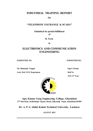
  • 1. INDUSTRIAL TRAINING REPORT On “TELEPHONE EXCHANGE & SCADA” Submitted for partial fulfillment of B. Tech. in ELECTRONICS AND COMMUNICATION ENGINEERING SUBMITTED TO: SUBMITTED BY: Mr. Himanshu Nagpal Sujeet Nirmal Asstt. Prof. ECE Department Roll No ECE 4th Year Ajay Kumar Garg Engineering College, Ghaziabad 27th Km Stone, Delhi-Hapur Bypass Road, Adhyatmik Nagar, Ghaziabad-201009 Dr. A. P. J. Abdul Kalam Technical University, Lucknow AUGUST 2019
  • 2. iii Preface Summer Trainings / Industrial Trainings are very important for engineering students. This training provides the opportunity to be familiar with the industrial / company environment. During this training they can show and can enhance their practical skills and gain practical knowledge and experience forfuture. This is bestway through which the students can learn the latest technologies being used in the companies. I SUJEET NIRMAL (ROLL NO) have undergone through Summer Training on “TELEPHONE EXCHANGE, ETS, MSS, SCADA” from “DieselLocomotive Works (DLW), VARANASI”. This training helped me a lot in learning the technologies of this particular field. Industrial Training was very challenging but as I proceeded things got easier. Practical Summer / Industrial Training was an interesting learning experience for me.
  • 3. iii Acknowledgement I want to express my sincere gratitude and thanks to Gp.Capt.Dr. P.K. Chopra (H.O.D., ECE Department and Training & Placement Cell), Ajay Kumar Garg Engineering College, Ghaziabad for granting me permission formy industrial training in the field of “Telephone Exchange, ETS, MSS, SCADA” I express my sincere thanks to Mr. Ashok Kumar for his cooperative attitude and consistenceguidance, due to which I was able to complete my training successfully. Finally, I pay my thankful regard and gratitude to the team members and technicians of “Diesel Locomotive Works (DLW)” and Ajay Kumar Garg Engineering College, Ghaziabad for their valuable help, support and guidance. Sujeet Nirmal Roll No 4th Year EC-3
  • 4. iv ABSTRACT The industrial training report of DLW (DIESEL LOCOMOTIVE WORKS) is various trade. i.e. Electronics and communication, Electrical, Mechanical, Electrical & Electronics and many engineering holders are participated. The content of my industrial topic Telephone Exchange, Maintenance Service Shop, Engine Testing Shop and Supervisory Control and Data Acquisition. we are discus about how to communicate the signal from transmitter to receiver. The second is ETS (Engine Testing Shop), I learn about testing of engine. After completed the Engine Testing Shop going to discuss about Maintenance Service Shop. Then the last of my section is SCADA, in this shop I learn the controlling of whole industrial and data through software. This report is written on the basis of practical knowledge of acquired by me during the period of practical training taken at, Diesel Locomotive Works Varanasi. This report is presented in very simple & understanding language and it is comprising of four sections namely Telephone Exchange, Maintenance Service Shop, Supervisory Control and Data Acquisition and Engine Testing Shop.
  • 5. v AJAY KUMAR GARG ENGINEERING COLLEGE 27th km Stone,Delhi-HapurBypassRoad,AdhyatmikNagar,Ghaziabad-201009 Phones:0120-2762841 to 2762851 Fax: o120-2761844, 2761845, 2762170 Email: akgecor@akgec.org Website : www.akgec.org TRAINING CERTIFICATE This is here to certify that Sujeet Nirmal student of Ajay Kumar Garg Engineering College, B. Tech 4th year Electronics & Communication branch, has undergone Industrial Training in Diesel Locomotive Work (DLW), Varanasi from 13-jun-2019 to 10-july-2019. Dr. P.K. Chopra Gp.Capt.Dr.P.K. Chopra Prof. & HOD VSM(Retd.) ECE Department Professor & HOD-T&P
  • 6. vi
  • 7. vii WEEKLY DAIRY Week -1 TELEPHONE EXCHANGE Introduction, Types of Exchange, Telephone Exchange in DLW, Standard Tones Signaling and Fault. Week -2 MAINTENANCE SERVICE SHOP Introduction, Electronics Lab, Meter, Shop, Battery Shop. Week -3 SUPERVISORY CONTROL & DATAACQUISITION Introduction, Field Instrumentation, Programmable Logic Controllers, Communication Network, Types of SCADA System, Control System Used in DLW. Week -4 ENGINE TESTING SHOP Engine Test Operation Sequence, Types of Tests, Procedure of Engine Testing, After Test Run
  • 8. TABLE OF CONTENTS Preface ii Acknowledge iii Abstract iv Training certificate v Industrial training Certificate vi CHAPTER 1: INTRODUCTION TO DLW 1-7 1.1 Background 1 1.2 Brief history 2 1.3 Product of DLW 2-3 1.4 Salient Feature 3 1.5 Design Office 4 1.6 Material Control Office 4 1.7 Store Department 4-5 1.8 Inspection Department 5 1.9 Account Department 5 1.10 Production Department 5 1.10.1 Block Division 5 1.10.2 Engine Division 5 1.10.3 Loco Division 5-6 1.10.4 Service Division 6 1.11 Personal Department 6 1.12 Research & Development 6 1.13 Recent milestone 6 1.14 Future Plans 7
  • 9. CHAPTER 2: TELEPHONE EXCHANGE 8-12 2.1 Introduction 8 2.2 Types of Exchange 8 2.2.1 Local Exchange 8 2.2.2 Transit Exchange 8 2.3 Telephone Exchange in DLW 9 2.4 Internal Distribution Frame 10 2.5 Main Distribution Frame 10-11 2.6 Distribution Box 11 2.7 Types of standard Tones 12 2.8 Signaling 12 2.9 Fault 12 CHAPTER 3: MAINTENANCE SERVICE SHOP 13-15 3.1 Introduction 13 3.2 Electronics Lab 14 3.3 Battery Shop 14-15 3.4 Meter Shop 15 CHAPTER 4: SUPERVISORY CONTROL & DATA ACQUISITION 16-22 4.1 Introduction 16-17 4.2 Major Components of SCADA 17-19 4.2.1 Field Instrumentation 17-18 4.2.2 Programmable Logic Controllers 18 4.2.3 Communication Network 18 4.2.4 I/O Server 19 4.2.5 Historian 19 4.3 Types of SCADA System 19-21 4.3.1 Early SCADA System 19 4.3.2 Distributed SCADA System 20
  • 10. 4.3.3 Network SCADA System 20 4.3.4 Internet of Things 20-21 4.4 Control System Used in DLW 21 4.5 Functions 22 CHAPTER 5: ENGINE TESTING SHOP 23-25 5.1 Engine Test Operation Sequence 23 5.2 Types of Tests 23-24 5.2.1 Water Test 23 5.2.2 Load Test 24 5.2.3 Run Down Test 24 5.3 Procedure of Engine Testing 24-25 5.3.1 At Final Load Test 25 5.3.2 Starting of Diesel Engine 25 5.4 After Test Run 25 CHAPTER 6: CONCLUSION 26 References 27
  • 11. 1 CHAPTER 1 INTRODUCTION TO DLW 1.1 Background Diesel Locomotive Works (DLW) is production unit under the ministry of railways. This was setup in collaboration with American locomotive company (ALCO) USA in 1961 and the first locomotive was rolled out in 1964. This unit produces diesel electronic locomotives and DG sets for Indian railways and other customers in India and Abroad. Subsequently a contract for transfer of technology of 4000 HP Microprocessor Controlled AC/AC Freight (GT 46 MAC) / passenger (GT 46 PAC) locomotives and family of 710 engines has been signed with electro motive division of general motors of USA for manufacture in DLW. The production of these locomotives has now started and thus DLW is the only manufacturers of Diesel Electric Locomotives with both ALCO and General motors' technologies in the world. FIG 1.1 Loco Engine
  • 12. 2 1.2 Brief History Set up in 1961 as a green-field project in technical collaboration with ALCO/USA to Manufacture Diesel Electric Locomotives. First locomotive rolled out and dedicated to nation in January, 1964. Transfer-of-Technology agreement signed with General Motors/ USA in October, 95 to manufacture state-of-the-art high traction AC-AC diesel locomotives. A flagship company of Indian Railways offering complete range of flanking products in its area of operation. State-of-the art Design and Manufacturing facility to manufacture more than 150 locomotives per annum with wide range of related products viz. components and sub- assemblies. Unbeatable trail-blazing track record in providing cost-effective, eco-friendly and reliable solutions to ever-increasing transportation needs for over three decades. Fully geared to meet specific transportation needs by putting Price Value-Technology equation perfectly right. A large base of delighted customers among many countries viz. Sri Lanka, Malaysia, Vietnam, Bangladesh, Tanzania to name a few, bearing testimony to product leadership in its category. 1.3 Products of DLW DLW is an integrated plant and its manufacturing facilities are flexible in nature. These can be utilized for manufacture of different design of locomotives of various gauges suiting customer requirements and other products. The product range available is as under:  WDG4 4000 HP AC/AC Freight Traffic Locomotive  WDP4 4000 HPAC/AC Broad-Gauge High-Speed Locomotive  WDG3D 3400HPAC/AC Broad Gauge Mixed Traffic Micro-Processor ControlledLocomotive.  WDM3C 3300HPAC/DC Broad Gauge Mixed Traffic Locomotive.  WDM3A 3100HPAC/DC Broad Gauge Mixed Traffic Locomotive.
  • 13. 3  WDP3A 3100 HP AC/DC Broad-Gauge High-Speed Passenger Locomotive.  WDG3A 3100HPAC/DC BroadGauge Freight Locomotive.  WDM2 2600HPAC/DC Broad Gauge Mixed Traffic Locomotive.  WDP1 2300 HP AC/DC Broad Gauge Intercity Express Locomotive.  WDM7 2150HPDC/DC Broad Gauge Mixed Traffic Locomotive.  WDM6 1350HPDC/DC Broad Gauge Mixed Traffic Locomotive.  YDM4 1350 HP AC/DC & DC/DC Broad Gauge Mixed Traffic Locomotive.  EXPORT LOCO 2300 HP AC/DC Meter Gauge/Cape gauge Mixed Traffic Locomotive.  Diesel Generating Sets 800 KW to 2500 KW  Spare Parts for engines, locomotives and generating sets. 1.4 Salient Features: - Annual production capacity 125 Locomotives Annual turn-over (Rs) 5000 million Total number of staff 7223 Workshop land 89 Hectares Township area 211 Hectares Covered area in shops 86300m2 Covered area of other service buildings 73700m2 Electrical power requirement 3468 KVA (Average maximum demand)
  • 14. 4 1.5 Design Office: - Prepare diag. of each part and sent to Material Control & inform timely in any change in any parts to relative department. FIG 1.2 3D Modal of Diesel Locomotive 1.6 Material control office: - Prepared material list (ml) which consists diag. & qty. of each part and sent to store departments for purchase. FIG 1.3 Fork Lift Truck 1.7 Store Department: - After receiving of ML, Store Departments scrutiny the ML, take Funds
  • 15. 5 & vetting from Account department & then issue tenders, Open Tenders & Purchase Order issued. After Receiving of Material inspection has done by Inspection Department. 1.8 Inspection Department: - After Receiving of Material inspection has done by Inspection dept. If material is OK then Receipt Note issued by Store Dept. and sent to Acct. Department for payment to firm. If material is not OK Then inform to firm to collect the rejected material. 1.9 Account Department: - Check all the purchase, given concurrence for purchase, vett the ML/Requisition & payment to firms. 1.10 Production Shop Production shops are divided in three divisions- 1. Block Divisions 2. Engine Divisions 3. Loco Divisions 1.10.1 Block Division 1. Heavy Weld Shop 2. Heavy Machine Shop 1.10.2 Engine Division 1. Engine Erection Shop 2. Engine Testing Shop 3. Light Machine Shop 4. Sub Assembly Shop 5. Rotor Shop 6. Heat Treatment Shop 1.10.3 Loco division 1. Loco Frame Shop 2. Pipe Shop 3. Truck Machine Shop 4. Traction Assembly Shop 5. Sheet Metal Shop
  • 16. 6 6. Loco Assembly Shop 7. Loco Paint Shop 8. Loco Test Shop 1.10.4 Service Shop 1. Maintenance Areas 2. Tool Room 3. Central Transport Shop 1.11 Personal Department Prepare payment of Staff, Leave Record, Personal Record of every employee, Housing allotment, welfare of staff etc. 1.12 Research & development  R & D - a Customer centric Activity Committed to Innovation and Continuous Improvement;  Highly skilled Manpower capable of handling complete R&D activities;  A sophisticated design center with modern CAD/ CAE workstations equipped with Unigraphics andAnsys;  Back-up support from RDSO, a centralized R&D organization at corporate level;  Several milestones in the past - an enviable pedigree viz.  original ALCO design made 7% more fuel efficient; 1.13 Recent milestone: - Transfer of technology (TOT) -- An added feather in the cap: -  Agreement with General Motors of USA for technology transfer to manufacture high horse-power GT46MAC 4000HP AC/AC locomotive in India;  Only country outside North-Americatohave this bleeding edge technology Many export/repeats orders complied successfully in recent past and many more in the pipeline; Supplied more than 400 locomotives to various non- railway customers; Emerging as a leading manufacturer of ALCO/ GM locomotives for developing countries.
  • 17. 7 1.14 FuturePlans:- Assimilation of GM technologyto manufacturetheir latest710 series of diesel electric locomotives.  To emergeas a globally competitivelocomotivemanufacturer.  To develop as an export hub for ALCO/GM locos for Asianmarket.  To followan export led growthstrategy throughcontinuous improvement.
  • 18. 8 CHAPTER 2 TELEPHONE EXCHANGE 2.1 Introduction: A telephone exchange is a telecommunications system used in the public switched telephone network or in large enterprises. An exchange consists of electronic components and in older systems also human operators that interconnect (switch) telephone subscriber lines or virtual circuits of digital systems to establish telephone calls between subscribers. In the public telecommunication networks a telephone exchange is located in a central office (CO), typically a building used to house the inside plant equipment of potentially several telephone exchanges, each serving a certain geographical exchange area. Central office locations are often identified in North America as wire centers, designating a facility from which a telephone obtains dial tone. For business and billing purposes, telephony carriers also define rate centers, which in larger cities may be clusters of central offices, to define specified geographical locations for determining distance measurements. In the United States and Canada, the Bell System established in the 1940s a uniform system of identifying each telephone exchange with a three-digit exchange code, or central office code, that was used as a prefix to subscriber telephone numbers. All exchanges within a larger region, typically aggregated by state, were assigned a common area code. With the development of international and transoceanic telephone trunks, especially driven by direct customer dialing, similar efforts of systematic organization of the telephone networks occurred in many countries in the mid-20th century.
  • 19. 9 2.2 TYPES OF EXCHANGE: - 2.2.1 Local Exchanges: Local exchanges service the subscribers within a particular area e.g. a district of a city or a locality. They switch incoming traffic to and outgoing traffic from the connected subscriber. The number of subscribers connected to an EWSD exchange can be as low as a few hundred or as high as 250000. 2.2.2 Transit Exchanges: At node points in the telephone network transit exchanges connect together trunks to and from other exchanges up to 60,000 incoming outgoing or both ay trunks can be connected to EWSD transit or long-distance exchanges 2.3 TELEPHONE EXCHANGE IN DLW: -  Provides telephone connections to the D.L.W. administrative blocks and D.L.W. colony area.  This exchange is also provided by the rack type Main Distribution Board (MDF).  This has capacity to mount the fuse mounting with fuses and test jacks.  This exchange is designed to perform satisfactorily for a line loop resistance of 100 ohms for each subscriber.  The local loop is the physical loop or circuit that connects from the demarcation point of the customer premises to the edge of the telecommunication service provider’s network.  The exchange works on the D.C. supply of 50 volts obtained from the battery set which is connected in parallel to the charger which is operating on 230 volts A.C.  The voltage required when two subscriber talks are 12 volts.
  • 20. 10 2.4 Internal Distribution Frame (IDF): In IDF the framing of jumper is done. The cables which are coming out of exchange are terminated in IDF. In IDF the numbers are connected in series wire and thus it makes easier to find out the number in the IDF whenever some complication arises. In Railway Telephone exchange there are two type of IDF- a) Crown type installed by the Tata Company b) Block type installed just beside the MDF Fig 1.2 IDF 2.5 Main Distribution Frame (MDF) The exchange is also provided in the Rack type of Tag Block, which is called MDF. In MDF we mount the fuse hold tag at the back of the Block and at the front of the Jumper. There are 40 Blocks in a single frame where 20 are of B side making the number B1-B20 and other 20 are on the F side making with F1-F20. In MDF the numbers are distributed here and then according to distribution of the cables the record of the numbers is maintained. Installation of the Tag Block in the MDF makes it easier to find the fault between MDF and IDF.
  • 21. 11 FIG 1.3 MDF 2.6 Distribution Box(DB) It is a box type board in which cable pads are distributed according to the number which are to be provided near the distribution. DB are installed after a certain interval of the distance making a proper distribution of cable which is easier with the consumers. FIG 1.4 ID
  • 22. 12 2.7 TYPES OF STANDARD TONES: -  Busy Tone (BT)-Engage tone or busy tone I tone which dialer hear due to engage of call. 400Hz applied for 0.75sec and disconnected for 0.75sec.  Number Unobtainable (NU)-400Hz applied continuously 2.5sec on and 0.5sec off.  Ringing Tone- It is the ring which we hear on calling.133Hz interrupted at the same frequency at the ringing current.  Dial Tone- It is the continuous tone which we hear on incoming call at dialer’s end. 33Hz applied continuously. 2.8 Signaling The sending of a signal from the transmitting end of a telecommunication circuit to inform that user at the receiving end that a message is to be sent. There are three types of signaling used in India-  Ring Down (RD) signaling.  Loop Disconnect (LD) signaling.  Open Dialing (OD) signaling. 2.9 Fault: -  Line Contact- It means that the drop wire is connected either with a pole or a tree if it is broken down, a husky voice is obtained when we ring.  Line Earth- It means that drop wire breaks on its own when it touches a pole or a tree. A soft humming sound comes when we dial a number.  Line Disc- The wire has been broken down.
  • 23. 13 CHAPTER 3 MAINTENANCE SERVICE SHOP 3.1 Introduction: Maintenance, repair, and overhaul involve fixing any sort of mechanical, plumbing or electrical device should it become out of order or broken (known as repair, unscheduled, or casualty maintenance). It also includes performing routine actions which keep the device in working order (known as scheduled maintenance) or prevent trouble from arising (preventive maintenance). MRO may be defined as, "All actions which have the objective of retaining or restoring an item in or to a state in which it can perform its required function. The actions include the combination of all technical and corresponding administrative, managerial, and supervision actions. FIG 3.1 Maintenance Shop of DLW MSS is the unit in which Maintenance & repair the device that include: 1. Electronics lab 2. Battery shop 3. Meter shop
  • 24. 14 3.2 Electronics Lab: There is a full-fledged Electronic Lab to cater to maintenance need of highly sophisticated CNC machines and component / subassembly level trouble shooting of PCBs, Servo Drives, and Microprocessor based controllers and electronic units. This Lab also supports other Zonal Railways in repair of PCBs. IMPORTANT MACHINES: - (i) Reverse Engineering System-It helps tracing PCB tracks between components in given circuit board whose detail is not pro- vided by the OEM. (ii) Automatic Test Equipment-With its library having more than 30,000 components details, it helps in-circuit testing of digital and analog devices mounted on latest PCBs. FIG 3.2 View of Electronics Lab 3.3 Battery Shop: An electric battery is a device consisting of two or more electrochemical cells that convert stored chemical energy into electrical energy. Each cell has a positive terminal, or cathode, and a negative terminal, or anode. The terminal marked positive is at a higher electrical potential energy than is the terminal marked negative. The terminal marked positive is the source of electrons that when connected to an external circuit will flow and deliver energy to an external de- vice. When a battery is connected to an external circuit, Electrolytes are able to move as ions within, allowing the chemical reactions to be completed at the separate terminals and so deliver energy to the external circuit. It is the movement of those ions within the battery which allows current to flow out of the battery to perform work.
  • 25. 15 Although the term battery technically means a device with multiple cells, single cells are also popularly called batteries. FIG 3.3 Internal Part of Battery Chemical action during discharge Pbo2 + H2 + H2SO4= PBSO4 + 2H2O (at + Ve plate) ------ (i) Pb + SO4 = PbSO4 (at – Ve plate) --------------- (ii) Chemical action during charging PbSO4 + H2 = Pb + H2SO4(at – Ve plate) ------------- (iii) PbSO4 + SO4 + 2H2O = PbO2 +2H2O (at + Ve plate) ------- (iv) 3.4 Meter Shop: Meter (in locomotive) is a device that measure’s the amount of loco speed, air pressure, Fuel, diesel pressure, power of electricity and meter- calibration etc. FIG 3.4 View of MeterLab
  • 26. 16 CHAPTER 4 SUPERVISORY CONTROL AND DATA ACQUISITION 4.1 Introduction: SCADA is a system for remote monitoring and control that operates with coded signals over communication channels “using typically one communication channel per remote station”. It is an industrial computer- based control system employed to gather and analyze the real-time data to keep, track, monitor and control industrial equipment in different types of industries. SCADA in power system can be defined as the power distribution application which is typically based on the software package. The electrical distribution system consists of several substations; these substations will have multiple number of sensors, controllers and operator- interface points. FIG 4.1 SCADA System
  • 27. 17 from a SCADA Host software platform. This provides process control locally so that these devices turn on and off at the right time, supporting your control strategy and a remote method of capturing data and events (alarms) for monitoring these processes. SCADA Host platforms also provide functions for graphical displays, alarming, trending and historical storage of data. Historically, SCADA products have been produced that are generic with a ‘one shoe fits all’ approach to various markets. As SCADA has matured to provide specific solutions to specific SCADA markets it has provided solutions for wide area network SCADA systems that rely on tenuous communication links. 4.2 MAJOR COMPONENTS OF SCADA: - ▪ Field instrumentation ▪ Programmable Logic Controllers/Remote Terminal Unit ▪ Communication network ▪ SCADA host software FIG 4.2 Components of SCADA 4.2.1 Field instrumentation: Instrumentation is a key component of safe and optimized control system. Traditionally operator controlled the devices manually, now a day’s instruments would have been fitted with feedback sensors such as limit switches, providing connectivity from these devices into a local P.L.C.s and R.T.U., to relay data to the SCADA host software. Sensors and End Devices: Sensors detect and transmit readings of important parameters to P.L.C.s. End devices include equipments from valves to large machinery
  • 28. 18 like pump, supply and industrial chillers are controlled by the PLCs to start, stop and function as required. 4.2.2 Programmable Logic Controllers: PLCs are electronic brains that scan thousands of rungs or lines of custom code to execute predetermined logic based on the inputs from the readings of the sensors in order to control the outputs which are the end devices of the plant. These normally happens autonomously without requiring input from operator. These are sometimes called Process Automation Controllers (PAC) or may have close cousins called Remote Terminal Units (RTU). FIG 4.3 PLCs PLCs are used instead of RTUs because of the advantages of PLCs like flexibility, configuration, versatile and affordability compared to RTUs. 4.2.3Communication Network: Generally, the combination of radio and direct wired connections is used for SCADA systems, but in case of large systems like power stations and railways SONET/SDH are frequently used. Among the very compact SCADA protocols used in SCADA systems – a few communication protocols, which are standardized and recognized by SCADA vendors – send information only when the supervisory station polls the RTUs.
  • 29. 19 4.2.4 I/O Server: I/O server are computers that communicate to PLCs via industrial Ethernet to obtain the sensor values as well as other representative data of the status of the processes in the plant or facility and further distributes them to the operator stations and historian. 4.2.5 HISTROIAN: The historian is normally a server with a large hard disk capacity to log reading of the sensors as well as other plant data, alarms and event logs. For smaller systems, the I/O servers, operator stations and historian can be the same desktop computer. 4.3 TYPES OF SCADA SYSTEM: - There are different types of SCADA systems that can be considered as SCADA architectures of four different generations: ▪ First Generation: Monolithic or Early SCADA systems ▪ Second Generation: Distributed SCADA systems ▪ Third Generation: Network SCADA systems ▪ Fourth Generation: Internet of things technology SCADA systems 4.3.1 Early SCADA System: All the remote terminal unit sites would connect to a back-up mainframe system for achieving the first-generation SCADA system redundancy, which was used in case of failure of the primary mainframe system. The functions of the monolithic SCADA systems in the early first generation were limited to monitoring sensors in the system and flagging any operations in of surpassing programmed alarm levels. FIG 4.4 Early SCADA System
  • 30. 20 4.3.2 Distributed SCADA System: In the second generation, the sharing of control functions is distributed across the multiple systems connected to each other using Local Area Network (LAN). Hence, these were termed as distributed SCADA systems. These individual stations were used to share real-time information and command processing for performing control tasks to trip the alarm levels of possible problems. FIG 4.5 Distributed SCADA System 4.3.3 Network SCADA System: The current SCADA systems are generally networked and communicate using Wide Area Network (WAN) Systems over data lines or phone. These systems use Ethernet or Fiber Optic Connections for transmitting data between the nodes frequently. These third generation SCADA systems use Programmable Logic Controllers (PLC) for monitoring and adjusting the routine flagging operators only in case of major decisions requirement. FIG 4.6 Network SCADA System 4.3.4 Internet of Things: In fourth generation, the infrastructure cost of the SCADA systems is reduced by adopting the internet of things technology with the commercially
  • 31. 21 available cloud computing. The maintenance and integration are also very easy for the fourth generation compared to the earlier SCADA systems. FIG 4.7 Internet of Things 4.4 Control System Used in DLW: - FIG 4.8 Control System
  • 32. 22 4.5 Functions: -  SUPERVISION OF THE COMPLETE SUBSTATIONS-Graphical display of measurement values, positions of breakers, alarm management, trending management, disturbance.  COMMAND-Command of all motorized devices including MV breakers and DC breakers.  PARAMETERIZATION- Parameter setting of all protection relays.  CONTROL- Possibility to define special control sequences.
  • 33. 23 CHAPTER 5 ENGINE TESTING SHOP When all the perform are done then finally engine come in ETS, for the first inspection report and after this it will be agreed for the performance. 5.1 Engine Test Operation Sequence 1. Base inspection under screen and fitting over screen 2. Water circulation. 3. Lube oil filling and check deflection crank shaft. 4. Lube oil circulation. 5. Pre run on no load 3 to 5 times of duration 10 to 30 min each 400 rpm. 6. Intermediate runs 12 runs of 30 min duration each from 400 to 1000 rpm. 7. Check over speed trip of recheck 3 times. 8. Check bake in nozzles and set tapped clearance. 9. Inspection before fist hour performance. 10. First hour performance on full load. 11. Base inspection. 12. Second hour performance on full load. 13. Attend defects of first hour performance. 14. Final base inspection. 15. Check engine deficiencies. 16. Engine clearance 5.2 Types of Tests: - 5.2.1 Water Test- Water acts as a coolant for moving part of the engine because constant movement or rotation causes various parts to heat up and water working as coolant cooled down the concerned part.
  • 34. 24 5.2.2 Load Test- For load testing electrical load is provided to the engine. If there is any abnormal sound then the engine is again tested for lubrication so that any flaw which is there can be removed. FIG 5.1 Engine testing 5.2.3 Run Down Test: It is done to check the air of the turbo charger or in other words this test is done to ensure that good amour of air being supplied to the cylinder by super charger. 5.3 Procedure of Engine Testing: - The following instruction should be mode before engine testing 1. Cleaning of test bed 2. Lifting of engine by overhead crane capacity 30 tans 3. Cleaning of mounting pad lowering of engine on the test bed 4. Diagonally tightening of mounting pad bolts Generator end 2’’ two nos Free end 1 1/2’’ two nos 5. Completion of all the auxiliary’s connections as under: 5.1 Water system 5.2 LO system 5.3 FO system 5.4 AIR system 5.6 Governor oil system
  • 35. 25 6. Filling of water (chromate water) 7. Connection of brake in filter and filling of LO up to full marked on deep slick 8. Checking of crank shaft deflection maxim allowance 0.0008’’ 9. Connection of all the thermo couples 10. LO circulation 11. Filling of full oil 12. Application of indictor cock 5.3.1 At Final load Test: 1. Fuel oil piping of leak 2. LO pump and piping for leak 3. Exhaust manifold for leak 4. Air manifold for leak 02/02 Fuel Injection Pump & Nozzle Section-this section will carry out the repairing and testing of pump of nozzles. 5. Water piping and pumps for leak 5.3.2 Starting of Diesel Engine: For starting of engine, the main traction generator in runs as a DC series motor using power from storage batteries 60 volts. 5.4 After Test Run: 1. Fuel pump secured 2. Check piston and liner securing Note: - The crank case inspection to be made after run test as piston, liners and all vital parts keep ending clean and tree of al repair leak checks all level and hold it at full mark.
  • 36. 26 CHAPTER 6 CONCLUSION As DLW focuses not on quantity, but on quality & satisfaction of its customers. It has always been in top of public sector companies. Last year DLW won second consecutive time “BEST PRODUCTION UNIT SHIELD OF2017-18” of Indians Railways. As vision of DLW is: - “To be a world class manufacturer of reliable, cost-effective state of art Diesel / Electric locomotives.” Mission of DLW is: - We shall achieve our vision through  Focus on quality for sustained and continuous improvement in reliability & perform ance on the product leading to customer satisfaction.  Developing core competence with due emphasis on innovation, human resource development team work.  Achieving environmental excellence by prevention of pollution, reduction of emission energy conservation and prevention of natural resources.
  • 37. 27 REFERENCES 1. https://en.wikipedia.org/wiki/Indian_Railways 2. https://en.wikipedia.org/wiki/Ministry_of_Railways_(India) https://en.wikipedia.org/wiki/Rail_transport 3. https://en.wikipedia.org/wiki/Fiber-optic_communication 4. http://www.indianrail.gov.in/enquiry/StaticPages/StaticEnquiry.jsp?StaticP age=international_Tourist.html&locale=en 5. http://www.indianrailways.gov.in/railwayboard/view_section_new.jsp?lan g=0&id=0,1 6. https://www.elprocus.com/basic-elements-of-fiber-optic-communication- system-and-its-working/