BLW SUMMER TRAINING REPORT
•
3 likes•3,501 views

Summer training project report at dlw after completation of 4 weeks training.

Recommended
More Related Content
What's hot
What's hot (20)
Similar to BLW SUMMER TRAINING REPORT
Similar to BLW SUMMER TRAINING REPORT (20)
Recently uploaded
Recently uploaded (20)
BLW SUMMER TRAINING REPORT
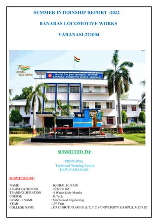
- 1. SUMMER INTERNSHIP REPORT -2022 BANARAS LOCOMOTIVE WORKS VARANASI-221004 SUBMITTED TO: PRINCIPAL Technical Training Centre BLW/VARANASI SUBMITTED BY: NAME : IQUBAL HUSAIN REGISTRATION NO. : 2022071265 TRANING DURATION : 4 Weeks (July Month) COURSE : B.Tech. BRANCH NAME : Mechanical Engineering YEAR : 2nd Year COLLEGE NAME : SIR CHHOTU RAM I E & T, C C S UNIVERSITY CAMPUS, MEERUT
- 2. ACKNOWLEDGEMENT Summer training has an important role in exposing the real life situation in an industry. It was a great experience for me to work on training at BANARAS LOCOMOTIVE WORKSHOP through which I could learn to work in a professional environment. I would sincerely like to thank the employees and the officers of BLW, VARANASI for their help and support during the vocational training. Despite their busy schedules, they took time out for us and explained to us the various aspects of the working of the plant from the production shops. I would sincerely like to thank all the concerned engineers and senior officials who were instrumental in arranging the vocational training at BLW Varanasi, and without whose help and guidance the training could not have materialize. I express my deep sense of gratitude to Mr. Ramjanm Chaubey Sir (Principal TTC), BLW for given me such a great opportunity. IQUBAL HUSAIN M.E. 2nd Year SCRIET (CCSU, MEERUT)
- 3. CONTENTS [1] ACKNOWLEDGEMENT........................................................ [2] INTRODUCTION TO BLW………………………………… [3] MAINTAINANCE SERVICE SHOP (MSS)……………….. [4] SHEET METAL SHOP (SMS) …………………………….. [5] HEAT TREATMENT SHOP (HTS)………………………… [6] HEAVY MACHINE SHOP (HMS) …….…………………… [7] CONCLUSION………………………………………………. [8] BIBLIOGRAPHY...…………………………………………...
- 4. INTRODUCTION TO BLW The Banaras Locomotive Works (BLW) (formerly Diesel Locomotive Works (DLW)) in Varanasi, India, is a production unit of Indian Railways. DLW stopped manufacturing diesel locomotives in March 2019 and was renamed BLW in Oct 2020. Banaras Locomotive Works Type Indian Railways production unit Industry Electric locomotive Predecessor Diesel Locomotive Works Founded August 1961; 61 years ago Headquarters Varanasi, Uttar Pradesh India Area served India & South East Asian Countries Key people Anjali Goyal (General Manager) Products WAP 7 WAG 9 WAG 11 Owner Indian Railways Website blw.indianrailways.gov.in Banaras Locomotive Works i.e. BLW was formerly known as Diesel Locomotive Works (DLW). It is a locomotive production unit of Indian Railways. "DLW" stopped manufacturing diesel locomotives in March 2019 and its name was changed to Banaras Locomotive Works (BLW) in October 2020. The foundation stone of DLW (Diesel Locomotive Works) was laid on 23 April 1956 by the first President of India Late Rajendra Prasad and on August 1961 Banaras Locomotive Works was established as "DLW". Three years later, on 3 January 1964, DLW released its Broad Gauge Locomotive (WDM-2) by (Late)
- 5. Shri Lal Bahadur Shastri. It has produced several variants based on the GM EMD designs of the 1990s, with the original ALCO design from the 1960s. Banaras Locomotive Works has consistently won the "Best Production Unit Shield 2015-16, 2016-17, 2017-18" of Indian Railways. In March 2018, it successfully created history by converting two old ALCO Diesel Loco WDG3A into Electric Loco WAGC-3 (WAG-10). This happened for the first time in the world. Before discontinuing diesel loco production, DLW was the largest diesel- electric locomotive manufacturer in India. Altogether BLW has manufactured 8298 Diesel and 1050* Electric Rail Locomotives. In March 2019, it developed the country's first bi-mode locomotive, WDAP- 5. Today, Banaras Locomotive Works produces mostly electric locomotives WAP-7, WAG-9, WAG-11.
- 6. Due to the hard work and efficiency of the workers of this factory, orders are being received for making engines from many countries. In addition to Indian Railways, BLW regularly exports locomotives to countries such as Sri Lanka, Nepal, Bangladesh, Mali, Senegal, Tanzania, Angola, Mozambique and Vietnam and some users within India such as ports, large power and steel plants and private railways. Offers its services to.
- 7. PRODUCTS OF BLW 1. Indian locomotive class WAP-7 Type and origin Power type Electric Builder Chittaranjan Locomotive Works, Banaras Locomotive Works, Patiala Locomotive Works Build date 1999 - present Total produced 1423 as of July 2022 Specifications Gauge 5 ft 6 in (1,676 mm) Bogies Co-Co, Fabricated Flexi coil Mark IV bogies; bogie wheelbase 1,850 mm (72+7⁄8 in) + 1,850 mm (72+7⁄8 in) Wheel diameter 1,092 mm (43 in) new, 1,016 mm (40 in) worn Wheelbase 15,700 mm (51 ft 6+1⁄8 in) Length: • Over beams 20,562 mm (67 ft 5+1⁄2 in) Width 3,152 mm (10 ft 4+1⁄8 in) Height: • Pantograph 4,255 mm (13 ft 11+1⁄2 in) Axle load WAP 7 20.5 t (20.2 long tons; 22.6 short tons) WAP 7HS 18.08 t (17.79 long tons; 19.93 short tons) Loco weight 123 t (121 long tons; 136 short tons) Power supply 3-phase 2180 V 50 Hz Electric system/s 25 kV 50 Hz AC Overhead
- 8. Current pickup(s) Pantograph Traction motors 6FRA 6068 3-phase squirrel-cage induction motors 850 kW (1,140 hp), 2180 V, 1283/2484 rpm, 270/310A; Weight-2,100 kg (4,600 lb), forced-air ventilation, axle-hung, nose-suspended; Torque 6,330–7,140 N⋅m (4,670– 5,270 lbf⋅ft) ~88% efficiency. Transmission Electric Gear ratio WAP 7 72:20 WAP 7HS 70:22 Loco brake Air and regenerative Train brakes Air
- 9. The Indian locomotive class WAP-7 is a class of 25 kV AC electric locomotives that was developed in 1999 by Chittaranjan Locomotive Works (CLW) for Indian Railways. The model name stands for broad gauge (W), AC Current (A), Passenger traffic (P) engine, 7th generation (7). They entered service in 2000. A total of 1423 WAP-7 have been built, with more units being built at CLW, Banaras Locomotive Works (BLW) and Patiala Locomotive Works (PLW). The WAP-7 is one of the most successful locomotives of Indian Railways serving passenger trains for over 22 years. It is a passenger variant of the WAG- 9 freight locomotive with a modified gear ratio to pull lighter loads at higher speeds. With an output of 6,350 hp (4,740 kW), it is the most powerful passenger locomotive in the Indian Railways fleet, and the most numerous passenger locomotive in India, with a total of 1423 locomotives built as of April 2022. The WAP-7 is capable of hauling 24 coach trains at speeds 110–140 km/h (68– 87 mph) 2. Indian locomotive class WAG-9 WAG-9 Type and origin Power type Electric Builder Chittaranjan Locomotive Works, Electric Locomotive Works (Bhusawal), Bharat Heavy Electricals Limited, Banaras Locomotive Works, Patiala Locomotive Works Build date 1995 - present Total produced 3284 as of July 2022 Specifications Configuration: • UIC Co′Co′ Gauge 5 ft 6 in (1,676 mm)
- 10. Bogies Adtranz Fabricated Flexicoil IV Wheel diameter New:1,092 mm (3 ft 7 in), Half worn:1,054 mm (3 ft 5+1⁄2 in) Full worn:1,016 mm (3 ft 4 in) Wheelbase 15.7 m (51 ft 6 in) Length 20.562 m (67 ft 5+1 ⁄2 in) Width 3.152 m (10 ft 4+1⁄8 in) Height 4.525 m (14 ft 10+1⁄8 in) Axle load WAG-9 : 20.5 tonnes (20.2 long tons; 22.6 short tons) WAG-9H/Hi/9i : 22.0 tonnes (21.7 long tons; 24.3 short tons) Loco weight WAG-9 : 123 tonnes (121 long tons; 136 short tons) WAG- 9H/9Hi/9i : 132 tonnes (130 long tons; 146 short tons) Electric system/s 25 kV 50 Hz AC Overhead Current pickup(s) dual pantographs Traction motors WAG- 9/9H/9i : Adtranz 6FRA6068 MU working 2 Loco brake Air and Regenerative Train brakes Air Safety systems Slip/slide control, Main overload relay, Over voltage relay, No volt protection, Vigilance Control Device, Fire Detection Equipment, Fire Extinguishers and Earth fault relay
- 11. The Indian locomotive class WAG-9 is a class of 25 kV AC electric locomotives that was developed in 1995 by ABB Group (ABB) for Indian Railways. The model name stands for broad gauge (W), AC Current (A), Goods traffic (G), 9th generation (9) locomotive. They entered service in 1996. A total of 3284 WAG-9 have been built at Chittaranjan Locomotive Works (CLW), with more units being built at Banaras Locomotive Works (BLW), Bharat Heavy Electricals Limited (BHEL) and Patiala Locomotive Works (PLW). It was the most powerful freight locomotive of its fleet until the formal introduction of the WAG-12. The WAG-9 is one of the most successful locomotives of Indian Railways serving freight trains for over 26 years. A passenger variant of the WAG-9 was developed namely the WAP-7 locomotive by modifying the gear ratio to pull lighter loads at higher speeds. Nowadays, It is a common locomotive used in freight trains.
- 12. MAINTAINANCE SERVICE SHOP (MSS) Maintenance shop is the combination of many shops. The shops which comes under the maintenance shop are a) Assembly Shop b) Machining Shop Many engine parts manufactured from various other shops are machined and assembled in the maintenance shop. They include: 1. ASSEMBLY SHOP a) Camshaft Assembly b) Crankshaft Assembly c) Governor Assembly d) Radiator Fan Assembly e) Lubrication Oil Pump and Water Pump Assembly f) Lube Oil Filter and Cooler g) Water Cooled Air Compressor for EMD Locomotives h) Fuel Pump Support Assembly i) OST Assembly 2. MACHINING SHOP a) The frontal engine surfaces b) Machining of assemblies after welding operations c) Machining of the various engine parts smooth operation d) Machining of the inside holes and grooves
- 13. PRINCIPAL OF MAINTENCE (A) Breakdown Maintenance Break down of machine can occur due to the following two reasons: - a) Due to unpredictable failure of component which cannot be prevented. b) Due to gradual wear and tear of the parts of the machine which can be prevented by regular inspection known as preventive maintenance. (B) Preventive maintenance a) Also termed as “planned maintenance” or “systematic maintenance”. b) An extremely important function for the reduction of the maintenance cost and to keep the good operational condition of equipment. Objective of preventive maintenance a) To obtain maximum availability of the plant by avoiding break down and by reducing shut down period to a maximum. b) To keep the machine in proper condition so as to maintain the quality of the product. c) To ensure the safety of the workers. d) To keep the plant at the maximum production efficiency. e) To achieve the above objectives with most economical combination.
- 14. SHEET METAL SHOP (SMS) Machines Used in SMS: 1. CNC Shearing Machine 2. CNC Hydraulic Turret Press Punch Machine 3. Layer Cutting Machine 4. CNC Bending Machine 5. Angle Shear Machine 6. Oil Furnace 7. Axial Drilling Machine 8. MIG Welding wing CO2 9. Punching Machine 10. Band Saw Machine Operations: 1. Driver Cab 2. Hood Over Engine -Engine Hood -Cooling Hood -DB Hood
- 15. 1. Fully-Automatic CNC Shearing Machine Automation Grade Fully-automatic Brand HUBOW Max Shear Width 2000-3000 mm Material to be Sheared Stainless Steel, Carbon Steel Automatic Grade Automatic Working principle shearing machine ⑴ Shearing machine is widely used for direct shearing of various metal materials according to different needs. It is mainly used in steel manufacturing, shipbuilding, automobile, container manufacturing, switchgear, machinery manufacturing, and light industry. ⑵ The shearing machine is driven by the hydraulic system to press the pressing material to press the steel plate, and the left and right cylinders drive the tool holder to move up and down. The upper blade on the tool holder is fixed to the lower blade of the lower blade seat and adopts reasonable blade clearance and various thicknesses. The sheet metal is subjected to shearing forces to cause the sheet to break apart at the desired size.
- 16. 2 . CNC Bending Machine The CNC bending machine uses the equipped mold to bend the cold metal sheet into various geometric cross-sectional shapes. It is a sheet forming machine designed for cold-rolled sheet metal processing, and is widely used in sheet bending processing in industries such as automobiles, aircraft manufacturing, light industry, shipbuilding, containers, elevators, and railway vehicles. Features of CNC Bending Machine: 1. Direct angle programming with angle compensation function. 2. The grating ruler real-time detection feedback correction, full closed-loop control, back gauge and slider dead gauge positioning accuracy is ±0.02mm. 3. The upper mold adopts a quick clamping device, and the lower mold adopts a wedge deformation compensation mechanism. 4. With multi-step programming function, it can realize multiple automatic operation, complete one-time processing of multi-step parts, and improve production efficiency. 5. The imported hydraulic system with stable performance and compact structure can be selected according to user requirements, and the back gauge can be driven by ball screw and timing belt.
- 17. Operating procedures of CNC Bending Machine 1. Strictly abide by the safety operating procedures and wear labor protection equipment as required. 2. Before starting, carefully check whether the motor, switch, circuit and grounding are normal and firm, and check that the control parts and buttons of the equipment are stuck in the correct position. 3. Check the overlap and firmness of the upper and lower molds; check whether each positioning device meets the requirements of being processed. 4. When the upper slide plate and each positioning axis are not at the origin, run the return to origin program. 5. After the equipment is started, run dry for 1-2 minutes, and move on the slide for 2-3 times at full stroke. If abnormal sound or malfunction is found, stop immediately, remove the malfunction, and work after everything is normal. 6. When working, one person should command uniformly, so that the operators and the feeding and suppressing personnel should cooperate closely to ensure that the cooperating personnel are in a safe position before they can send out the bending signal. 7. When the sheet is bent, it must be compacted to prevent the sheet from lifting up and hurting people during bending. 8. The power supply must be cut off when adjusting the sheet metal die, and the operation should be stopped. 3. CNC Hydraulic Turret Press Punch Machine
- 19. CNC turret punch servo system is an automatic control system that controls the position and speeds of the moving parts of the machine tool, also known as follow-up system, drag system or servo mechanism. In CNC machine tools, the servo system receives the feed generated by the computer interpolation software. The pulse or feed displacement is transformed and amplified into the displacement of the moving part. The servo system can be divided into position servo (the position of the table and the position and starting angle of the main shaft) and speed servo (the speed of the rotation of the table motor). The composition and working principle of the servo system The CNC turret punch servo system consists of a speed loop and a position loop. As shown in the figure, this is a double closed-loop system. The inner loop is the speed loop and the outer loop is the position loop. Speed control is an important part of the servo system, and the speed loop consists of a speed control unit, a servo motor and a speed detection device. The speed control unit is used to control the speed of the motor and is the core of the speed control system. It is an independent unit, composed of speed regulator, current regulator and power drive amplifier. The detection devices used for speed feedback in the speed loop are tachogenerators, pulse encoders, etc. The position loop is composed of the position control module, speed control unit, position detection and feedback control in the CNC device. The position control is mainly to control the motion coordinate axis of the machine tool. The coordinate axis control is the required position control. It not only has strict requirements on the control of the movement speed and position accuracy of a single uranium, but also requires that each moving uranium has a Good dynamic coordination can ensure processing efficiency, processing accuracy and surface roughness. 【Analysis of the advantages and disadvantages of CNC turret punch press】 CNC turret punching machines have many advantages. They are: strong adaptability to parts and can process parts surfaces of complex shapes; high productivity; high machining accuracy and stable machining quality; shortened production preparation time, facilitated modern management; reduced labor for workers strength. (1) Compared with ordinary machine tools, CNC turret punching machines can improve production efficiency by 3 to 5 times, and use CNC machining center machine tools to achieve productivity of 5-10 times; (2) CNC turret punching machine can obtain higher machining accuracy than the machine tool itself; (3) Complex shape parts can be processed without special fixtures; (4) One machine can be used for multiple purposes, reducing labor intensity and saving plant area:
- 20. (5) It is conducive to the development of computer control and management, and is conducive to the development of comprehensive automation of machining; (6) The initial investment and maintenance technology of CNC turret punch presses are relatively high, and the quality of management and operators is also high. The CNC turret punching machine better solves the problems of complex shape, high precision, small production batch, short production cycle and frequent product replacement. It is a flexible and high-efficiency automatic machine tool. CAI (DNC), flexible manufacturing system (FMS), computer integrated manufacturing system (CIMS, computer integrated manufacturing) and other important devices for flexible processing and the basis of the temperament manufacturing system. CNC turret punching also has disadvantages. They are: expensive and large initial investment in equipment; high technical requirements for users and maintenance personnel due to the integration of mechanical, electrical, hydraulic and computer technologies; manual programming workload when processing complex-shaped parts. Band Saw Machine
- 21. HEAT TREATMENT SHOP (HTS) Different heat treatment operations like- Quenching, Normalising, Case Hardening, Stress Relieving, Induction Hardening are employed.Low steel or Class-II jobs are first carburised, i.e., the carbon content is increased on the surface before any heat treatment. The carburizing temperature is 920-930⁰C. Stress Relieving is a process of heating up to a lower critical temperature and holding there for a definite time before slow cooling. It’s purpose is to remove internal stresses. Example: a) Eng. Block - 640⁰C/10hrs. b) Cam Shaft - 450⁰C/4hrs. Induction Hardening is a process of surface hardening. It works on the principal of mutual induction; hardening by high frequency AC-current. The conditions are: a) Voltage – 410-450V b) Temperature - 840⁰C c) Quenching Pressure – 14-30psi d) Quenching Water Temperature – 20-30⁰C Heat treatment process is defined as: An operation or combination of operations Heating and Colling of a metal /alloy in solid state To obtain desirable Conditions, e.g., that of relieve stresses Properties e.g. -Better machinability - Improve ductility -Homogeneous structure.
- 22. PURPOSE a) Cause relief of internal stresses developed during cold working, forging etc. b) Harden and strengthen metal c) Improve machinability d) Change grain size e) Improve ductility and toughness f) Increase,heat,wear, and corrosion resistance of material STAGES OF HEAT TREATMENT a) Stage l—Heating the metal slowly to ensure a uniform temperature. b) Stage 2—Soaking (holding) the metal at a given temperature for a given time and cooling the metal to room temperature. c) Stage 3—Cooling the metal to room temperature. Stages of Heat Treatment
- 23. 2.1.1.Heat Treatment Process: a) Annealing (815 °C) b) Normalizing (815 °C) c) Hardening (815 °C) d) Tempering (200 °C – 300 °C) Fig.2.2. Heat Treatment (Phase Diagram) 2.1.2. STEEL COMPOSITION
- 24. Fig.2.3. Different Structures of Steel 2.1.3. ANNEALING PROCESS a) Annealing is the opposite of hardening b) Relieve internal stresses, soften them, make them more ductile, and refine their grain structures. c) Cooling method depend on the metal. For command use are furnace cooled. 2.1.4. NORMALIZING a) Metal is heated to a higher temperature and then removed from the furnace for air cooling. b) Remove the internal stresses induced by heat treating, welding, casting, forging, forming, or machining. c) low-carbon steels do not require normalizing (no harmful effects result). 2.1.5. HARDENING a) In practice, 0.80 % C is required for maximum hardness. b) When you increase the carbon content beyond 0.80 per cent, there is no increase in hardness, but there is an increase in wear resistance. c) This increase in wear resistance is due to the formation of a substance called hard cementite. 2.1.6. TEMPERING a) The minimum temperature time for tempering should be 1 hour. If the part is more than 1 inch thick, increase the time by 1 hour for each additional inch of thickness. b) Tempering relieves quenching stresses and reduces hardness and brittleness. PIT FURNACE
- 25. CARBURIZING FURNACE INDUCTION HARDENING MACHINE
- 26. Induction hardening is a method of quickly and selectively hardening the surface of a metal part. A copper coil carrying a significant level of alternating current is placed near (not touching) the part. Heat is generated at, and near the surface by eddy current and hysteresis losses. Quench, usually water-based with an addition such as a polymer, is directed at the part or it is submerged. This transforms the structure to martensite, which is much harder than the prior structure. A popular, modern type of induction hardening equipment is called a scanner. The part is held between centres, rotated, and passed through a progressive coil which provides both heat and quench. The quench is directed below the coil, so any given area of the part is rapidly cooled immediately following heating. Power level, dwell time, scan (feed) rate and other process variables are precisely controlled by a computer. Benefits of Induction Hardening Increased Wear Resistance There is a direct correlation between hardness and wear resistance. The wear resistance of a part increases significantly with induction hardening, assuming the initial state of the material was either annealed, or treated to a softer condition. Increased Strength & Fatigue Life due to the Soft Core & Residual Compressive Stress at the Surface The compressive stress (usually considered a positive attribute) is a result of the hardened structure near the surface occupying slightly more volume than the core and prior structure. Parts may be Tempered after Induction Hardening to Adjust Hardness Level, as desired As with any process producing a martensitic structure, tempering will lower hardness while decreasing brittleness. Deep Case with Tough Core Typical case depth is .030” - .120” which is deeper on average than processes such as carburizing, carbonitriding, and various forms of nitriding performed at sub-critical temperatures. For certain projects such as axels, or parts which are still useful even after much material has worn away, case depth may be up to ½ inch or greater.
- 27. HEAVY MACHINE SHOP (HMS) This shop carries out the machining of Cylinder BLOCK (M.G. & B.G.) main base, saddler Main bearing caps, Splines, Turbo Super Charger. Lube Oil, Fuel Oil & Water header bearing housing OPERATION: Planning. Milling, Drilling. Tapping. Boring Honing, Serration, milling etc. Types of Machine provided in the shop are: 1. Double Housing planned machine (32", 24", & 16") 2. Radial drilling machine. 3. Radial drilling machine Traveling type. 4. Boring Machine 5. Angular Boring Machine 6. Tracer Planner machine. 7. Hill Acme king structural milling machine. TOOLS USE: 1. O.K. Tool (Rough & Finish) 2. CC Milling cutter (4", 9", & 10") 3 Boring Tipped Tool (Rough & Finish) 4. Honing Stone (For hand honing) MEASURING INSTRUMENT 1. Dial Bar gauge 2. Micron meter (out side and depth)
- 28. 3. Vernier Height gauge. 4. Vernier calipers 5. Mandrill or optical shad rill machine EX-CELLO ANGULAR BORING MACHINE:- Motor R.P.M. in constant, Spindle, speed is control by clutch system. H.M.T. ANGULAR BORING MACHINE:- Spindle speed is directly controlled through motor. (Coated carbide is used in H.M.T. angular Boring machine). Cylinder Block made of fabricated class II material except main bearing cop as it made class IV material. The machining of cylinder Block is complicated and challenging job. It required great skill and knowledge. After duly fabricated, stress relieved and shot blasted the block is subjected to layout to ensure availability of adequate machining allowance, where necessary and to provide guide linear for subsequent machining the weight of the block is 6:02 Tons approx. (Fabricated Material) After completion of all operations as per drawings the black subjected to inspection in addition to stage inspection dimension live radial distance between center of Crank bore and com bore, distance between center of com bore and liner seat etc. are checked at this stage the weight of the black is 05.02 tons apporx. 01 ton of material removed by the machining and then blank is block send for assembly. Two tools are used for boring both tools are fixed in slot of boring bar. Due to spindle rotation boring is done. Tool movement and machine action is governed by G Code and M Code respectively Absolute mode and incremental modes are used for tool movement. Single point cutting tool (two) is first fitted in devise block then in boring bar
- 29. ANGULAR BORING MACHINE HORIZONTAL BORING MACHINE
- 30. Main dimension of cylinder Block 1. Diameter of com bore = 4.750 to 4.7515" (B.G. & M.G.) 2. Diameter of blank bore = 9.0355 to 9.0370" (M.G. & B.G.) 3. Diameter of liner bore=10.750 to 10.752" (Upper) (B.G. of M.G.) = 10.621 to 10.623 (Lower) 4. Diameter of thirst Collar = 10sigma 5. Thickness of thrust bearing = 4,247" to 4.249" 6. Thickness of the plate free end = .." =gen. End = 1omega 7. Radial distance between the centers of crank of Cam bore 10 499 to 19.501" 8. Distance of liner seat from center of crank Bore 32.480" to 32.485" 9. Total length of the M.G. black =106.370" =106.380 10. Total length of main Bush B.G. = 172.380" B.G=172.370 11. Total length of main Bush M.G. = 117.130" = 117.120" 12 Total length of BG. Black =161.625 =161.630
- 31. TWO WAY ANGULAR BORING MACHINE BEHRINGER BAND SAW
- 32. DOUBLE HOUSING PLANNED MACHINE ⚫It is the standard model & most widely used. ⚫ Very heavy and robust. ⚫ Has a bed and two vertical housings are fixed. ⚫ Table moves along the guide ways of the bed. ⚫Housing supports cross rail & tool heads. ⚫ Cross rail carries two tool heads. ⚫Tool head carries tools.
- 33. RADIAL DRILLING MACHINE ⚫ Intended for drilling medium to large and heavy work piece. ⚫ m/c consists of a heavy, round, vertical column mounted on a large base. ⚫ Column supports a radial arm which can be raised and lowered to accommodate work pieces of different heights. ⚫ Arm may be swung around to any position over the work bed. ⚫ Drill head containing mechanism for rotating and feeding the drill is mounted on a radial arm and can be moved horizontally on the guide ways and clamped at any desired position. ⚫ The work may be mounted on the table or on the floor.
- 34. CONCLUSION The Mechanical maintenance is responsible for the running of BLW. It ensures that the all the machinery and equipment are running at their top performance level without being affected by failure and break down. Working with the engineers of the Mechanical maintenance department, I have gained such an amount of knowledge which would not have been possible in a classroom in a similar period of time. Also the practical experience have gained here in BLW, VARANASI gave me knowledge of to what extent my theoretical knowledge learnt in my college in applicable in the field. Although the theoretical knowledge forms the base of practical knowledge required on the field The field job also requires some different set of skills which I learnt about during my training. My skills in Mechanical engineering has definitely been taken to a much higher level than it was when I first joined the training programme of 4 weeks back and I truly consider myself highly fortunate to get this opportunity.
- 35. Bibliography 1 .SlideShare.net 2. www.wikipedia.com 3. https://blw.indianrailways.gov.in 4. https://www.hmtwatches.in