
Recommended
More Related Content
What's hot
What's hot (19)
Similar to Camd lab manual
Similar to Camd lab manual (20)
Recently uploaded
Recently uploaded (20)
Camd lab manual
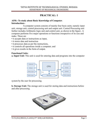
- 1. TATVA INSTITUTE OF TECHNOLOGICAL STUDIES, MODASA DEPARTMENT OF MECHANICAL ENGINEERING T.I.T.S/D.E/MECH./C.A.M.D/3RD SEM/LAB MANUAL Page 1 PRACTICAL: 1 AIM:- To study about Basic Knowledge of Computer. Introduction:- A computer system consists of mainly four basic units; namely input unit, storage unit, central processing unit and output unit. Central Processing unit further includes Arithmetic logic unit and control unit, as shown in the figure:. A computer performs five major operations or functions irrespective of its size and make. These are • it accepts data or instructions as input, • it stores data and instruction • it processes data as per the instructions, • it controls all operations inside a computer, and • it gives results in the form of output. Functional Units: a. Input Unit: This unit is used for entering data and programs into the computer system by the user for processing. b. Storage Unit: The storage unit is used for storing data and instructions before and after processing.
- 2. TATVA INSTITUTE OF TECHNOLOGICAL STUDIES, MODASA DEPARTMENT OF MECHANICAL ENGINEERING T.I.T.S/D.E/MECH./C.A.M.D/3RD SEM/LAB MANUAL Page 2 c. Output Unit: The output unit is used for storing the result as output produced by the computer after processing. d. Processing: The task of performing operations like arithmetic and logical operations is called processing. The Central Processing Unit (CPU) takes data and instructions from the storage unit and makes all sorts of calculations based on the instructions given and the type of data provided. It is then sent back to the storage unit. CPU includes Arithmetic logic unit (ALU) and control unit (CU).
- 3. TATVA INSTITUTE OF TECHNOLOGICAL STUDIES, MODASA DEPARTMENT OF MECHANICAL ENGINEERING T.I.T.S/D.E/MECH./C.A.M.D/3RD SEM/LAB MANUAL Page 3 • Arithmetic Logic Unit: All calculations and comparisons, based on the instructions provided, are carried out within the ALU. It performs arithmetic functions like addition, subtraction, multiplication, division and also logical operations like greater than, less than and equal to etc. • Control Unit: Controlling of all operations like input, processing and output are performed by control unit. It takes care of step by step processing of all operations in side the computer.
- 4. TATVA INSTITUTE OF TECHNOLOGICAL STUDIES, MODASA DEPARTMENT OF MECHANICAL ENGINEERING T.I.T.S/D.E/MECH./C.A.M.D/3RD SEM/LAB MANUAL Page 4 Memory Computer‟s memory can be classified into two types; primary memory and secondary memory a. Primary Memory can be further classified as RAM and ROM. RAM • RAM or Random Access Memory is the unit in a computer system. It is the place in a computer where the operating system, application programs and the data in current use are kept temporarily so that they can be accessed by the computer‟s processor. It is said to be „volatile‟ since its contents are accessible only as long as the computer is on. The contents of RAM are no more available once the computer is turned off. ROM or Read Only Memory is a special type of memory which can only be read and contents of which are not lost even when the computer is switched off. It typically contains manufacturer‟s instructions. Among other things, ROM also stores an initial program called the „bootstrap loader‟ whose function is to start the operation of computer system once the power is turned on. b. Secondary Memory. RAM is volatile memory having a limited storage capacity. Secondary/auxiliary memory is storage other than the RAM. These include devices that are peripheral and are connected and controlled by the computer to enable permanent storage of programs and data.
- 5. TATVA INSTITUTE OF TECHNOLOGICAL STUDIES, MODASA DEPARTMENT OF MECHANICAL ENGINEERING T.I.T.S/D.E/MECH./C.A.M.D/3RD SEM/LAB MANUAL Page 5 CD ROM Secondary storage devices are of two types; magnetic and optical. Magnetic devices include hard disks and optical storage devices are CDs, DVDs, Pen drive, Zip drive etc. • Hard Disk Hard disks are made up of rigid material and are usually a stack of metal disks sealed in a box. The hard disk and the hard disk drive exist together as a unit and is a permanent part of the computer where data and programs are saved. These disks have storage capacities ranging from 1GB to 80 GB and more. Hard disks are rewritable.
- 6. TATVA INSTITUTE OF TECHNOLOGICAL STUDIES, MODASA DEPARTMENT OF MECHANICAL ENGINEERING T.I.T.S/D.E/MECH./C.A.M.D/3RD SEM/LAB MANUAL Page 6 • Compact Disk Compact Disk (CD) is portable disk having data storage capacity between 650-700 MB. It can hold large amount of information such as music, full-motion videos, and text etc. CDs can be either read only or read write type. • Digital Video Disk Digital Video Disk (DVD) is similar to a CD but has larger storage capacity and enormous clarity. Depending upon the disk type it can store several Gigabytes of data. DVDs are primarily used to store music or movies and can be played back on your television or the computer too. These are not rewritable. Input / Output Devices: These devices are used to enter information and instructions into a computer for storage or processing and to deliver the processed data to a user. Input/Output devices are required for users to communicate with the computer. In simple terms, input devices bring information INTO the computer and output devices bring information OUT of a computer system. These input/output devices are also known as peripherals since they surround the CPU and memory of a computer system. Input Devices An input device is any device that provides input to a computer. There are many input devices, but the two most common ones are a keyboard and mouse. Every key you press on the keyboard and every movement or click you make with the mouse sends a specific input signal to the computer. • Keyboard: The keyboard is very much like a standard typewriter keyboard with a few additional keys. The basic QWERTY layout of characters is maintained to
- 7. TATVA INSTITUTE OF TECHNOLOGICAL STUDIES, MODASA DEPARTMENT OF MECHANICAL ENGINEERING T.I.T.S/D.E/MECH./C.A.M.D/3RD SEM/LAB MANUAL Page 7 make it easy to use the system. The additional keys are included to perform certain special functions. These are known as function keys that vary in number from keyboard to keyboard. • Mouse: A device that controls the movement of the cursor or pointer on a display screen. A mouse is a small object you can roll along a hard and flat surface. Its name is derived from its shape, which looks a bit like a mouse. As you move the mouse, the pointer on the display screen moves in the same direction. • Trackball: A trackball is an input device used to enter motion data into computers or other electronic devices. It serves the same purpose as a mouse, but is designed with a moveable ball on the top, which can be rolled in any direction.
- 8. TATVA INSTITUTE OF TECHNOLOGICAL STUDIES, MODASA DEPARTMENT OF MECHANICAL ENGINEERING T.I.T.S/D.E/MECH./C.A.M.D/3RD SEM/LAB MANUAL Page 8 • Touchpad: A touch pad is a device for pointing (controlling input positioning) on a computer display screen. It is an alternative to the mouse. Originally incorporated in laptop computers, touch pads are also being made for use with desktop computers. A touch pad works by sensing the user‟s finger movement and downward pressure. • Touch Screen: It allows the user to operate/make selections by simply touching the display screen. A display screen that is sensitive to the touch of a finger or stylus. Widely used on ATM machines, retail point-of-sale terminals, car navigation systems, medical monitors and industrial control panels. • Light Pen: Light pen is an input device that utilizes a light-sensitive detector to select objects on a display screen.
- 9. TATVA INSTITUTE OF TECHNOLOGICAL STUDIES, MODASA DEPARTMENT OF MECHANICAL ENGINEERING T.I.T.S/D.E/MECH./C.A.M.D/3RD SEM/LAB MANUAL Page 9 • Magnetic ink character recognition (MICR): MICR can identify character printed with a special ink that contains particles of magnetic material. This device particularly finds applications in banking industry. • Optical mark recognition (OMR): Optical mark recognition, also called mark sense reader is a technology where an OMR device senses the presence or absence of a mark, such as pencil mark. OMR is widely used in tests such as aptitude test. • Bar code reader: Bar-code readers are photoelectric scanners that read the bar codes or vertical zebra strips marks, printed on product containers. These devices are generally used in super markets, bookshops etc. Scanner:Scanner is an input device that can read text or illustration printed on paper and translates the information into a form that the computer can use. A scanner works by digitizing an image.
- 10. TATVA INSTITUTE OF TECHNOLOGICAL STUDIES, MODASA DEPARTMENT OF MECHANICAL ENGINEERING T.I.T.S/D.E/MECH./C.A.M.D/3RD SEM/LAB MANUAL Page 10 Output Devices: Output device receives information from the CPU and presents it to the user in the desired from. The processed data, stored in the memory of the computer is sent to the output unit, which then converts it into a form that can be understood by the user. The output is usually produced in one of the two ways – on the display device, or on paper (hard copy). •Monitor: is often used synonymously with “computer screen” or “display.” Monitor is an output device that resembles the television screen (fig. 1.8). It may use a Cathode Ray Tube (CRT) to display information. The monitor is associated with a keyboard for manual input of characters and displays the information as it is keyed in. It also displays the program or application output. Like the television, monitors are also available in different sizes. • Printer: Printers are used to produce paper (commonly known as hard copy) output. Based on the technology used, they can be classified as Impact or Non- impact printers. Impact printers use the typewriting printing mechanism wherein a hammer strikes the paper through a ribbon in order to produce output. Dot-matrix and Character printers fall under this category. Non-impact printers do not touch the paper while printing. They use chemical, heat or electrical signals to etch the symbols on paper. Inkjet, Deskjet, Laser, Thermal printers fall under this category of printers.
- 11. TATVA INSTITUTE OF TECHNOLOGICAL STUDIES, MODASA DEPARTMENT OF MECHANICAL ENGINEERING T.I.T.S/D.E/MECH./C.A.M.D/3RD SEM/LAB MANUAL Page 11 • Plotter: Plotters are used to print graphical output on paper. It interprets computer commands and makes line drawings on paper using multi colored automated pens. It is capable of producing graphs, drawings, charts, maps etc. • Facsimile (FAX): Facsimile machine, a device that can send or receive pictures and text over a telephone line. Fax machines work by digitizing an image.
- 12. TATVA INSTITUTE OF TECHNOLOGICAL STUDIES, MODASA DEPARTMENT OF MECHANICAL ENGINEERING T.I.T.S/D.E/MECH./C.A.M.D/3RD SEM/LAB MANUAL Page 12 PRACTICAL: 2 AIM:-To Study Of AutoCAD and AutoCAD Commands. Introduction:- AutoCAD is general purpose computer aided design and drafting programming which can prepare wide variety of 2D drawings and 3D drawings or models. The created drawing data file which can be retrieved at any time for drawing editing and plotting. It is powerful drawing tool that can be highly customizing a special application. It improves productivity of creating drawing because of increasing speed and accuracy as compared to traditional methods. The software of AutoCAD came this market in December 1982 and it was released in 1988. SELECTING COMMANDS IN AUTOCAD :- AutoCAD provided the different method to: a. Enter or select command b. Key board c. Pull-down menu d. Icon menu A. HELP:- Command: - Help[F1] Function: To obtain a list of AutoCAD Command. B. LIMITS:- Command: - limit (on/off) < lower left corner > < current valve> Function: - to designate to drawing boundaries for the current drawing and control to checking of those limits. C. POINT:- Command: - point Function: - to draw a point it can be used as mark or sharp point. D. LINE:- Command; line (L) specify first point; specify next point; or (undo) specify next point or (close/undo) E. CIRCLE:- Command: - circle (c) Specify center point of circle or (3p/2p/TTR) Specify radios at circle. Function: - it is use to draw a circle with the specify center and radios.
- 13. TATVA INSTITUTE OF TECHNOLOGICAL STUDIES, MODASA DEPARTMENT OF MECHANICAL ENGINEERING T.I.T.S/D.E/MECH./C.A.M.D/3RD SEM/LAB MANUAL Page 13 F. ARC:- Command; arc (a) Centre/ start point, Centre/ end/ < second point > angle/ length of Chord/ <end point > A include angle. Function: - To draw arc with different methods like:- Three points Start, Centre, end Start, Centre, included angle Start, Centre, length of chord Start, end, starting direction Start, end, radius Line/arc condition G. POLYGON:- Command: Polygon [PO] Number of sides : <edge/centre of polygon > inscribed circle/circle inscribed about circle [I/C] :- Radius at centre Function:- To Draw Polygon with edge or inscribed in circle or with inscribed about circle. H. ELLIPSE:- Commands: - Ellipse [el] Arc/Centre <axis end point> : arc end point rotation/< other axis Distance> rotation around rear axis. Function: - To draw ellipse with methods like end distance centre distance, End rotation and centre rotation. I. ERASE:- Commands: - Erase [e] Function: To remove unwanted objects from drawing permanently. J. MOVE:- Command: - Move [m] Select object base point or displacement second point of Displacement. Function: - To move one or more entities from their present location to new One without changing their orientation or size. K. ROTATE:- Command: - Rotate [Ro] Select object: Base point : <rotation angle>/reference angle<o>[value]new angle <value>.
- 14. TATVA INSTITUTE OF TECHNOLOGICAL STUDIES, MODASA DEPARTMENT OF MECHANICAL ENGINEERING T.I.T.S/D.E/MECH./C.A.M.D/3RD SEM/LAB MANUAL Page 14 Function: -To change the orientation of existing entities by rotating them About a specified base point. L. SCALE:- Commands: - scale [sc] Select object: - Base Point: [scale factor] reference:- reference length [l]: New length Function: -To change the size of existing. M. MIRROR:- Commands: - Mirror [Mi] Select Object: [items to be missed] First point of mirror line, second point: - Deleted old objects :-[M] Function: - To make mirror images at existing object in drawings N. STRETCH:- Command: - Stretch [S]. Select object to stretch try window. Select objects. Base point. New point. Function: - To move a selected portion of a drawing presenting connections to parts 68 the drawing in place. O. ARRAY:- Command: - Array [Ar] Selected portion of a drawing preserving connections to ports . Functions: To make multi-copies of selected object in a rectangular / polar pattern. P. BREAK:- Command: - Array [Ar]. Select object: [specify object to be broken] enter second pint. Function: - to erase port at a line type from circle are on 2d polyline. Q. TRIM:- Command: Trim [Tr] Select within edge. Select object. Function: - To trim some objects so they and precisely of a coating other objects. R. EXTENDS:- Command: - Extends [ex] Select boundary edge.
- 15. TATVA INSTITUTE OF TECHNOLOGICAL STUDIES, MODASA DEPARTMENT OF MECHANICAL ENGINEERING T.I.T.S/D.E/MECH./C.A.M.D/3RD SEM/LAB MANUAL Page 15 Select Object. Function: - To lengthen existing objects so they and precisely at boundary edge defined by object. S. FILLET:- Command: - Fillet [f]. Polyline / Radius/ trim / select two objects> [point to two objects] Function: - To connect two line are or circle by meant of a smoothly filled one of a specified radios . T. CHAMFER:- Command: - Chamfer [che]. Polyline / distance /<elect first line >:- [point to one line].select second liner :- [point to inter selected line ]. Function: - To trine interesting line in a specified distance from the inter setting and connect the trimmed ends with a new line segment. U. OFFSET:- Command: offset [o] offset distance of through [last]: select object to offset. Slide to offset to through point. Function: to construct an entity parallel to another entity at either a specified distance or through a specified point. V. DIVIDE:- Command: divide [div] Function: to divide entity into several entity at either a specified distance or through a specified point. W. MEASURE:- Command: measure [me] select object to measure <segment length>/ block Function : to measurement an entity placing X. ZOOM :- Command: zoom[z]. all/center/dynamic/extend/left/previous/window/<scale> Function: to increase or areas the apparent size of items being viewed in the current view. Part all through their actual size remain constant. Y. PAN:- Command: pan [p] displacement second point . Function: to view a lift portion of the drawing in the current view without changing the magnification.
- 16. TATVA INSTITUTE OF TECHNOLOGICAL STUDIES, MODASA DEPARTMENT OF MECHANICAL ENGINEERING T.I.T.S/D.E/MECH./C.A.M.D/3RD SEM/LAB MANUAL Page 16 Z. VIEW:- Command: view? /delete/restore/save/window:[select one] view name: [name] Function : to save current view parts to restore it later. AA. LAYER: Command: layer [la]. ?/make/set/new/on/off/color/types/freeze through select: Function: to create a new layer select the line type for designated layers, torn layers on and off. Just the defined. AB. COLOUR: Command: colour [col] New entity colour [c current>] Function: to set the current for sub sequently drawn entities. AC. LINE TYPE: Command: Line type /create load/ set: Function: - To set the current for sub- sequently drawn entities. AD. LINE TYPE SCALE:- Command: - LTS New scale factor. Function: - To set the current elevation and extra action thickness for sub-sequent entities being draw. To change the scale factor for drawing to derivation. AE. PEDIT :- Command:- pedit [Pe] Select polyline [one/two/many] entity selected is not a polyline. Do you want to turn into one? [Y] Close/join/width/edit vertex/find/spline/decurve/undo/exit. Function :- It is used for editing spline. AF. TAB SURF :- Command:-Tab Surf Select Path curve. Function: - To contract a polygon mesh approximately a tabulated surface by moving of specified direction vector along select path. AG. REV SURF:- Command: - rev surf. Select path curve, select axis of revolution: start angle [0] [<w=<w] Included angle [f= [w]]< full circle] Function: To construct a polygon mesh. Approximately a constant surface path Sounded by four edges of object selected.
- 17. TATVA INSTITUTE OF TECHNOLOGICAL STUDIES, MODASA DEPARTMENT OF MECHANICAL ENGINEERING T.I.T.S/D.E/MECH./C.A.M.D/3RD SEM/LAB MANUAL Page 17 AH. EDGE SURFACE:- Command: edge surface Select 1, select 2 Function: - To construct a polygon mesh approximately a cones surface path bounded by four edge object selected. AI. 3D MESH GENERAL POLYGON MESH:- Command: - 3D mesh Mesh M size [integer valve], mesh N size [integer value], vertex (m,n) [value] M code, N code very form 2 to 256. Function: - To construct a general polygon mesh vertex by vertex. AJ. UCS:- Command: - UCS Origin / Z-axis/ 3 point entity view/ x/y/z/ prev. / restore/ save / del/? [word] Function: - To define UCS AK. UCS ICON:- Command: - UCS icon On /off/ all/ on origin/ origin <current> on/ off state Function: - To change from one UCS to another.
- 18. TATVA INSTITUTE OF TECHNOLOGICAL STUDIES, MODASA DEPARTMENT OF MECHANICAL ENGINEERING T.I.T.S/D.E/MECH./C.A.M.D/3RD SEM/LAB MANUAL Page 18 PRACTICAL NO: 3 AIM : To Study of 3D Modeling Using Auto CAD. Introduction: To work in three dimensions in AutoCAD, we need to use a third axis on the rectangular (Cartesian coordinate system. This axis (defined as Z), determines the depth of an object. In this context, the X-axis will identify the WIDTH, the Y-axis LENGTH and the Z-axis determines the DEPTH of an object. 1. Start a new file from scratch. Accept all the default settings. 2. 2. Turn the Grid and Snap ON (F7 & F9), and use the default spacing. Command: grid <Enter> Specify grid spacing(X) or [ON/OFF/Snap/Major/aDaptive/Limits/Follow/Aspect] <0.5000>: L <Enter> Display grid beyond Limits [Yes/No] <Yes>: n <Enter> Command: <Enter>
- 19. TATVA INSTITUTE OF TECHNOLOGICAL STUDIES, MODASA DEPARTMENT OF MECHANICAL ENGINEERING T.I.T.S/D.E/MECH./C.A.M.D/3RD SEM/LAB MANUAL Page 19 Specify grid spacing(X) or [ON/OFF/Snap/Major/aDaptive/Limits/Follow/Aspect] <0.5000>: d <Enter> Turn adaptive behavior on [Yes/No] <Yes>: n <Enter> Command: <Enter> GRID Specify grid spacing(X) or [ON/OFF/Snap/Major/aDaptive/Limits/Follow/Aspect] <0.5000>: .5 <Enter> {Press F7 to turn the grid ON} Command: <Grid on> Command: z <Enter> ZOOM Specify corner of window, enter a scale factor (nX or nXP), or [All/Center/Dynamic/Extents/Previous/Scale/Window] <real time>: a <Enter> 3.Create a new layer named object, assign the color green to it, and make it the current layer. 4. Enter the ELEV Command and set the new default elevation at 1” and the new default thickness at 3”. Command: elev <Enter> Specify new default elevation <0.0000>: 1 <Enter> Specify new default thickness <0.0000>: 3 <Enter> 5. Begin you drawing with the LINE Command, and construct the figure 1.Do not be concern about the exact sizes. Keep your drawing proportional to one shown in Figure 1. 6. Use the VPOINT and set it to SE Isometric. Command: vpoint <Enter> Current view direction: VIEWDIR=0.0000,0.0000,1.0000
- 20. TATVA INSTITUTE OF TECHNOLOGICAL STUDIES, MODASA DEPARTMENT OF MECHANICAL ENGINEERING T.I.T.S/D.E/MECH./C.A.M.D/3RD SEM/LAB MANUAL Page 20 Specify a view point or [Rotate] <display compass and tripod>: 1,-1,1 <Enter> Regenerating model. You may access this command from “View” pull down menu. (Figure 2) Your drawing in SE Isometric will look similar to one shown in figure 3 7. Changing the Elevation and Thickness Command: elev <Enter> Specify new default elevation <1.0000>: -1 <Enter> Specify new default thickness <3.0000>: 6 <Enter>
- 21. TATVA INSTITUTE OF TECHNOLOGICAL STUDIES, MODASA DEPARTMENT OF MECHANICAL ENGINEERING T.I.T.S/D.E/MECH./C.A.M.D/3RD SEM/LAB MANUAL Page 21 PLAN VIEW 3D View 8. Add a circle as shown on Figure 4 and view from SE Isometric. 8. From the “View” Pull Down menu ,select “Hide”, or enter the HIDE command from the keyboard.
- 22. TATVA INSTITUTE OF TECHNOLOGICAL STUDIES, MODASA DEPARTMENT OF MECHANICAL ENGINEERING T.I.T.S/D.E/MECH./C.A.M.D/3RD SEM/LAB MANUAL Page 22 Creating Primitives BOX Start a new file from scratch. Accept all the default settings. 1. Use the VPOINT and set it to SE Isometric. 2. Use the pull-down menu or the toolbar to select the desired command. You may also type in command line. Command: vpoint <Enter>
- 23. TATVA INSTITUTE OF TECHNOLOGICAL STUDIES, MODASA DEPARTMENT OF MECHANICAL ENGINEERING T.I.T.S/D.E/MECH./C.A.M.D/3RD SEM/LAB MANUAL Page 23 Current view direction: VIEWDIR=0.0000,0.0000,1.0000 <Enter> Specify a view point or [Rotate] <display compass and tripod>: 1,-1,1 <Enter> Regenerating model. Command: box <Enter> Specify first corner or [Center]: {Pick a point anywhere on screen} Specify other corner or [Cube/Length]: L <Enter> Specify length: 4 <Enter> Specify width: 3 <Enter> Specify height or [2Point]: 2 <Enter> Figure
- 24. TATVA INSTITUTE OF TECHNOLOGICAL STUDIES, MODASA DEPARTMENT OF MECHANICAL ENGINEERING T.I.T.S/D.E/MECH./C.A.M.D/3RD SEM/LAB MANUAL Page 24 PRACTICAL: 4 AIM:-To Study of 2D parametric drawings. Introduction:- Geometry in parametric drawing is constrained with a set of mathematical and geometrical rules with respect to other geometries of the drawing. A parametric approach to design offers a big list of advantages over classical non-parametric design approach. Consider a scenario where you have completed designing a part having complex geometry. Suddenly you realize that something needs to be changed in the drawing. Making that change will affect your complete design, and with each change you need to update its dependent component geometry manually. That‟s a tedious enough job by itself, but what if the same issue happens with an assembly drawing? You get the point; it will be a nightmare to update every part and then the overall assembly to ensure changes are properly reflected everywhere! It‟s also clearly apparent that this task will be error prone and it will cost you extra design hours. Now, if the design is made with a parametric approach, then a design change will automatically update any dependent geometry, eliminating the chances for human error and, best of all, saving you lots of design editing time. Parametric Feature in AutoCAD The parametric constraint feature was added to AutoCAD 2010, making drawing with AutoCAD much more efficient. With AutoCAD you can apply geometric and dimensional constraints to your drawing, and with the parameters manager you can also add formulas to your drawing. These formulas can be used to define relationships between different parts of the geometry. I will explain the usage of parametric features on a sample 2D drawing. I will demonstrate it using both geometric and dimensional constraints, and also how to use the parameters manager for adding formulas to dimensional constraints. Applying Geometric Constraint Let‟s take, for example, this geometry where we have a circle inside a polygon in such a way that the circle is tangent to both the non-parallel sides of the
- 25. TATVA INSTITUTE OF TECHNOLOGICAL STUDIES, MODASA DEPARTMENT OF MECHANICAL ENGINEERING T.I.T.S/D.E/MECH./C.A.M.D/3RD SEM/LAB MANUAL Page 25 polygon. This geometry is completely unconstrained and changing the length of any side of the polygon or radius of the circle will break the tangency in the geometry. Circle tangent to opposite non-parallel side of a polygon. (All images courtesy of the author.) To ensure that the relationship between the circle and the non-parallel lines is maintained, I will apply a tangent geometric constraint between them. Select the Parametric tab from AutoCAD‟s drafting and annotation workspace and click on Tangent Constraint from the Geometric panel. Next click on circle, then on bottom horizontal line. A new tangent constraint will be added between the objects and a box containing an icon of tangential constraint will appear near the point of tangency. Repeat the process of applying a tangential constraint between the circle and top inclined line of the geometry. Now the circle is constrained with respect to both lines but the polygon itself is not constrained. A change in the circle geometry will force the polygon to change. In order to constrain the polygon, start with the Fix geometric constraint and click on the left endpoint of the bottom horizontal line. This will ensure that polygon‟s bottom left point will remain fixed in space. To ensure that the bottom line remains horizontal, select Horizontal constraint and click on the bottom horizontal line of polygon. To ensure that both vertical lines of the polygon remain perpendicular to the bottom horizontal line we need to apply a perpendicular constraint. Select Perpendicular from the Geometric panel and click on the left vertical line of polygon and then on the bottom horizontal line. Repeat the process with the right vertical line as well.
- 26. TATVA INSTITUTE OF TECHNOLOGICAL STUDIES, MODASA DEPARTMENT OF MECHANICAL ENGINEERING T.I.T.S/D.E/MECH./C.A.M.D/3RD SEM/LAB MANUAL Page 26 Now that all the relevant geometric constraints are in place, we need to apply dimensional constraints to make the drawing fully constrained. Applying Dimensional Constraint As the name suggests, dimensional constraints will restrict dimensions of geometry to a specified value.When that value is subsequently changed, the geometry will also update itself to match. Select Linear from Dimensional panel and now click on bottom horizontal line of polygon near left end, then click at right end of line and place the constraint at a convenient location. Repeat the process for both vertical lines of the polygon as well. Now the geometry is almost completely constrained except for the circle in the middle; the radius of the circle is still not fixed and it can be changed. To constrain the radius of circle select Radius from Dimensional Constraints panel and click on circle, then place the parameter at a suitable point.
- 27. TATVA INSTITUTE OF TECHNOLOGICAL STUDIES, MODASA DEPARTMENT OF MECHANICAL ENGINEERING T.I.T.S/D.E/MECH./C.A.M.D/3RD SEM/LAB MANUAL Page 27 Using Formulas to Manipulate Geometry Using formulas, the relationship between different parts of the geometry can be established in such a way that if the geometry changes, it does so in a controlled manner with respect to the formulas defined. Let‟s define some formulas so that all dimensional parameters of the drawing will be controlled with the radius of circle. Click on Parameters Manager on the Manage panel of the Parametric tab. Alternatively, you can also use the PARAMETERS command. Once the command is active, you will see a palette as shown below: Parameters manager displaying all currently defined dimensional constraints. You will see a list of all dimensional constraints used in the drawing. Double click in the blank area under the last constraint and a new user parameter will be added with default name user1. Change the name of the parameter to A by double clicking on its name. Now double click in front of parameter A under expressions column and enter this expression: ((rad1*2)+1)/2. This expression will define value of parameter A with respect to the value of rad1. Similarly, add one more user parameter, give it name B and enter expression (rad1^2)+1.
- 28. TATVA INSTITUTE OF TECHNOLOGICAL STUDIES, MODASA DEPARTMENT OF MECHANICAL ENGINEERING T.I.T.S/D.E/MECH./C.A.M.D/3RD SEM/LAB MANUAL Page 28 Then create a third user parameter, C, and assign an expression B*2. This expression will ensure that the value of parameter C will directly depend on parameter B, which is in turn is dependent on the value of rad1. Now our drawing is ready for accepting user parameter values. Now go to the dimensional constraints in the Parameters Manager palette and double-click on the d1 constraint in the expression column and change its value to C. Similarly, change the value of d2 to A and d3 to B. After making all these changes, this is how parameters manager palette will look: User-defined dimensional parameters using formulas. Now all of the dimensions of geometry are directly dependent on the value of rad1 parameter. You will notice an fx symbol before the name of every dimensional constraint on the drawing. This symbol appears when a dimensional constraint references one or more user parameters. These constrains appear only in the drawing area; they will not appear in your plot. The fx symbol facilitates recognition of parameter-dependent constraints to avoid accidental changes of these values or to understand situations where you might over-constrain the geometry.
- 29. TATVA INSTITUTE OF TECHNOLOGICAL STUDIES, MODASA DEPARTMENT OF MECHANICAL ENGINEERING T.I.T.S/D.E/MECH./C.A.M.D/3RD SEM/LAB MANUAL Page 29 To test our drawing, change the value of the rad1 parameter by double clicking on it and assign a value 3 to it. You will notice that complete geometry changes according to the defined formulas or expressions of Parameters Manager palette. Conclusion The parametric drawing feature of AutoCAD makes your drawing changes very efficient and fast. For a beginner it might be little confusing, but with practice this feature will add much value to your drawing. With this feature, design change becomes a very seamless task and it also minimizes chances of making mathematical errors while doing manipulations. If you have not yet tried this feature, I recommend you give it a shot. I am sure you will not be disappointed with the results.
- 30. TATVA INSTITUTE OF TECHNOLOGICAL STUDIES, MODASA DEPARTMENT OF MECHANICAL ENGINEERING T.I.T.S/D.E/MECH./C.A.M.D/3RD SEM/LAB MANUAL Page 30 PRACTICAL: 5 AIM:-To Study of Orthographic projection. Introduction:- Orthographic projection (or orthogonal projection) is a means of representing a three-dimensional object in two dimensions. It is a form of parallel projection, where all the projection lines are orthogonal to the projection plane,resulting in every plane of the scene appearing in affine transformation on the viewing surface. A lens providing an orthographic projection is known as an (object-space) telecentric lens. The term orthographic is also sometimes reserved specifically for depictions of objects where the axis or plane of the object is also parallel with the projection plane, as in multiview orthographic projections. Origin The orthographic projection has been known since antiquity, with its cartographic uses being well documented. Hipparchus used the projection in the 2nd century BC to determine the places of star-rise and star-set. In about 14 BC, Roman engineer Marcus Vitruvius Pollio used the projection to construct sundials and to compute sun positions. Vitruvius also seems to have devised the term orthographic (from the Greek orthos (= “straight”) and graphē (= “drawing”) for the projection. However, the name analemma, which also meant a sundial showing latitude and longitude, was the common name until François d'Aguilon of Antwerp promoted its present name in 1613. The earliest surviving maps on the projection appear as woodcut drawings of terrestrial globes of 1509 (anonymous), 1533 and 1551 (Johannes Schöner), and 1524 and 1551 (Apian). Multiview orthographic projections Multiview orthographic projection With multiview orthographic projections, up to six pictures of an object are produced, with each projection plane parallel to one of the coordinate axes of the object. The views are positioned relative to each other according to either of two schemes: first-angle or third-angle projection. In each, the appearances of views may be thought of as being projected
- 31. TATVA INSTITUTE OF TECHNOLOGICAL STUDIES, MODASA DEPARTMENT OF MECHANICAL ENGINEERING T.I.T.S/D.E/MECH./C.A.M.D/3RD SEM/LAB MANUAL Page 31 onto planes that form a 6-sided box around the object. Although six different sides can be drawn, usually three views of a drawing give enough information to make a 3D object. These views are known as front view, top view and end view.
- 32. TATVA INSTITUTE OF TECHNOLOGICAL STUDIES, MODASA DEPARTMENT OF MECHANICAL ENGINEERING T.I.T.S/D.E/MECH./C.A.M.D/3RD SEM/LAB MANUAL Page 32
- 33. TATVA INSTITUTE OF TECHNOLOGICAL STUDIES, MODASA DEPARTMENT OF MECHANICAL ENGINEERING T.I.T.S/D.E/MECH./C.A.M.D/3RD SEM/LAB MANUAL Page 33 PRACTICAL: 6 AIM:-To Study of Assembly Drawings. Introduction:- Definitions : What is an assembly drawing and why do we need them?
- 34. TATVA INSTITUTE OF TECHNOLOGICAL STUDIES, MODASA DEPARTMENT OF MECHANICAL ENGINEERING T.I.T.S/D.E/MECH./C.A.M.D/3RD SEM/LAB MANUAL Page 34 An assembly drawing is a drawing of an entire machine . We need to know how to put the machine together. Subassembly Drawing Subassembly: Two or more parts that form a portion of an assembly. Can you think of some examples of subassemblies? A car differential A motorbike engine A compressor in an AC Working Drawing Package Working Drawing Package: A packet of drawings that gives the specifications necessary to manufacture a design. A typical working drawing package includes; an assembly drawing, detailed drawings, and a standard parts sheet. A standard part sheet contains information about purchased items and will not be discussed in this course. Drawing Order: Drawings included in a working drawing package should be presented in the following order. Assembly drawing (first sheet) Part Number 1 Part Number 2 .... Standard parts sheet (last sheet) Views Used in Assembly Drawings Selecting Views: Does an assembly drawing need a FRONT, TOP and RIGHT SIDE view? Sometimes We need as many views as it takes to identify and locate each part. It may only take one view.
- 35. TATVA INSTITUTE OF TECHNOLOGICAL STUDIES, MODASA DEPARTMENT OF MECHANICAL ENGINEERING T.I.T.S/D.E/MECH./C.A.M.D/3RD SEM/LAB MANUAL Page 35
- 36. TATVA INSTITUTE OF TECHNOLOGICAL STUDIES, MODASA DEPARTMENT OF MECHANICAL ENGINEERING T.I.T.S/D.E/MECH./C.A.M.D/3RD SEM/LAB MANUAL Page 36 Sectional Views Sectional views are used quite often when drawing assemblies. Why? Assemblies often have parts fitting into or overlapping other parts and we need to look inside the assembly to see clearly.
- 37. TATVA INSTITUTE OF TECHNOLOGICAL STUDIES, MODASA DEPARTMENT OF MECHANICAL ENGINEERING T.I.T.S/D.E/MECH./C.A.M.D/3RD SEM/LAB MANUAL Page 37
- 38. TATVA INSTITUTE OF TECHNOLOGICAL STUDIES, MODASA DEPARTMENT OF MECHANICAL ENGINEERING T.I.T.S/D.E/MECH./C.A.M.D/3RD SEM/LAB MANUAL Page 38
- 39. TATVA INSTITUTE OF TECHNOLOGICAL STUDIES, MODASA DEPARTMENT OF MECHANICAL ENGINEERING T.I.T.S/D.E/MECH./C.A.M.D/3RD SEM/LAB MANUAL Page 39
- 40. TATVA INSTITUTE OF TECHNOLOGICAL STUDIES, MODASA DEPARTMENT OF MECHANICAL ENGINEERING T.I.T.S/D.E/MECH./C.A.M.D/3RD SEM/LAB MANUAL Page 40
- 41. TATVA INSTITUTE OF TECHNOLOGICAL STUDIES, MODASA DEPARTMENT OF MECHANICAL ENGINEERING T.I.T.S/D.E/MECH./C.A.M.D/3RD SEM/LAB MANUAL Page 41
- 42. TATVA INSTITUTE OF TECHNOLOGICAL STUDIES, MODASA DEPARTMENT OF MECHANICAL ENGINEERING T.I.T.S/D.E/MECH./C.A.M.D/3RD SEM/LAB MANUAL Page 42 Exercise: 1 Draw Following Orthographic Figures & Give Dimensions. Figure: 1 Figure: 2
- 43. TATVA INSTITUTE OF TECHNOLOGICAL STUDIES, MODASA DEPARTMENT OF MECHANICAL ENGINEERING T.I.T.S/D.E/MECH./C.A.M.D/3RD SEM/LAB MANUAL Page 43 Figure:3 Figure:4
- 44. TATVA INSTITUTE OF TECHNOLOGICAL STUDIES, MODASA DEPARTMENT OF MECHANICAL ENGINEERING T.I.T.S/D.E/MECH./C.A.M.D/3RD SEM/LAB MANUAL Page 44 Exercise: 2 Draw Following Isometrics Figures & Give Dimensions. Figure: 1 Figure: 2
- 45. TATVA INSTITUTE OF TECHNOLOGICAL STUDIES, MODASA DEPARTMENT OF MECHANICAL ENGINEERING T.I.T.S/D.E/MECH./C.A.M.D/3RD SEM/LAB MANUAL Page 45 Figure: 3 Figure: 4