SlideShare a Scribd company logo
1 of 32
DESIGN OF FLYWHEEL
Flywheel Application
A Flywheel is used to maintain constant angular
velocity of the crankshaft in a reciprocating
engine. In this case, the flywheel—which is
mounted on the crankshaft— stores energy
when torque is exerted on it by a firing piston
and it releases energy to its mechanical loads
when no piston is exerting torque on it.
INTRODUCTI
ON
FLYWHEEL
• A flywheel is an inertial energy-storagedevice.
• It absorbs mechanical energy and serves as a reservoir, storing energy
during the period when the supply of energy is more than the requirement
and releases it during the period when the requirement of energy is more
than the supply.
FLYWHEELS-FUNCTION NEED
AND OPERATION
•The main function of a fly wheel is to smoothen out variations in the
speed of a shaft caused by torque fluctuations. If the source of the driving
torque or load torque is fluctuating in nature, then a flywheel is usually
called for. Many machines have load patterns that cause the torque time
function to vary over the cycle. Internal combustion engines with one or
two cylinders are a typical example. Piston compressors, punch presses,
rock crushers etc. are the other systems that have fly wheel.
•Flywheel absorbs mechanical energy by increasing its angular velocity
and delivers the stored energy by decreasing itsvelocity.
FLYWHEEL MATERIALS
Traditionally, flywheel are made of cast iron. From design consideration, cast
iron flywheel offer the following advantages:-
• Cast iron flywheels are the cheapest.
• Cast iron flywheel can be given any complex shape without involving
machining operations.
• Cast iron flywheel has excellent ability to damp vibrations.
however, cast iron has poor tensile strength compare to steel. The failureof
cast iron is sudden and total. The machinability of cast iron flywheel is
poor compared to steel flywheel.
Applications
Providing continuous energy when the energy source is
discontinuous. For example, flywheels are used in
reciprocating engines because the energy source, torque from
the engine, is intermittent.
Delivering energy at rates beyond the ability of a continuous
energy source. This is achieved by collecting energy in the
flywheel over time and then releasing the energy quickly, at
rates that exceed the abilities of the energy source.
Dynamic balancing of rotating elements.
Energy storage in small scale electricity generator sets
Advance and Modern Flywheel
Flywheels have also been proposed as a power booster for
electric vehicles. Speeds of 100,000 rpm have been used to
achieve very high power densities.
Modern high energy flywheels use composite rotors made with
carbon-fibre materials. The rotors have a very high strength-to-
density ratio, and rotate at speeds up to 100,000 rpm. in a
vacuum chamber to minimize aerodynamic losses.
Benefits in Aerospace
Flywheels are preferred over conventional batteries in many
aerospace applications because of the following benefits:
5 to 10+ times greater specific energy
Lower mass / kW output
Long life. Unaffected by number of charge / discharge
cycles
85-95% round trip efficiency
Fewer regulators / controls needed
Greater peak load capability
Reduced maintenance / life cycle costs
Disadvantages
There are safety concerns associated with flywheels due to
their high speed rotor and the possibility of it breaking
loose & releasing all of it's energy in an uncontrolled
manner.
Its Bulkier, adds more weight to the vehicle.
Energy stored in a flywheel
Rotational Kinetic Energy, E = ½ Iω2
where,
I - moment of inertia of the flywheel (ability of an
object to resist changes in its rotational velocity)
ω - rotational velocity (Rad / sec)
The moment of inertia, I = kMr 2
where,
M - mass of the flywheel
r - radius of flywheel
k - inertial constant.
k depends on the shape of the rotating object.
Shape-factor K for different planar stress geometries
So for a solid disk ; I = Mr 2 /2
Co efficient of fluctuation of speed ( Cs )
The difference between the max and min speeds during a cycle is
called the max fluctuation of speed.
The ratio of the max fluctuation of speed to the mean speed is
called coefficient of fluctuation of speed.
Cs = (N1- N2 )/N
= 2( N1-N2 ) / N1 +N2
where N1 = max speed in r.p.m.
N2 = min speed in r.p.m.
N = mean speed in r.p.m.
= (N1 + N2) / 2
Permissible values for CS
S.NO Types of machines Coefficient of fluctuation of speed (CS)
1 Engines with belt
transmission
0.030
2 Gear wheel transmission 0.020
3 Crushing machines 0.200
4 Electrical machines 0.003
5 Hammering machines 0.200
6 Pumping machines 0.03-0.05
7 Machine tools 0.030
Stresses in a flywheel rim
A flywheel consists of a rim at which the major portion of the
mass or weight of flywheel is concentrated, a boss or hub for
fixing the flywheel on to shaft and a number of arms for
supporting the rim on the hub.
The following stresses are induced in the rim.
Tensile stress due to centrifugal force.
Tensile bending stress caused by the restraint of the arms.
Stresses in flywheel arms
The following stresses are induced in the arms of the
flywheel.
Tensile stresses due to centrifugal force acting on the
rim
Bending stress due to the torque transmitted from the
rim to the shaft or from the shaft to the rim.
1. Tensile stress due to the centrifugal force.
The tensile stress in the rim due to the centrifugal force, assuming
that the rim is unstrained by the arms, is determined in the similar
way as the thin cylinder subjected to internal pressure.
ft = ρ.R2.ω2 = ρ.v2 ( v = R.ω )
When ρ is in kg/m3, v is in m/sec, ft will be in N/m2
where ρ = density of the flywheel material
ω = angular speed of the flywheel
R = mean radius of the flywheel
v = linear velocity of the flywheel
2.Tensile bending stress caused by restraint of arms.
The tensile bending stress in the rim due to the restraint of arms is
based on the assumption that each portion of the rim between a
pair of arms behaves like a beam fixed at both ends and
uniformly loaded, such that length between fixed ends,
L = π.D/n = 2.π.R / n
where n - number of arms
The max bending moment,
M =w.l2/12=b.t.ρ.ω2.R/12(2.π.R/n)
Section modulus, Z =1/6 (b.t2)
So bending stress fb =M/Z =b.t.ρ.ω2.R/12(2.π.R/n) *
6 / (b.t2)
Total stress in the rim
f =ft +fb
Construction of Flywheel
Flywheels are typically made of steel and rotate on
conventional bearings; these are generally limited to
a revolution rate of a few thousand RPM
The flywheel of smaller size( upto 600 mm dia )are casted in one
piece. The rim and the hub are joined together by means of web.
Construction
If flywheel is of larger size (upto 2-5 meters diameter ), then it
is made of arms.
The number of arms depends upon the size of the flywheel and
its speed of rotation. But the flywheels above 2-5 meters are
usually casted in two pieces. Such a flywheel is known as “
split flywheel “.
A split flywheel has the advantage of relieving the shrinkage
stresses in the arms due to unequal rates of cooling of casting.
DESIGN APPROACH
There are two stages to the design of a flywheel.
• First, the amount of energy required for the desired degree ofsmoothening
must be found and the (mass) moment of inertia needed to absorb that
energy determined.
• Then flywheel geometry must be defined that caters the required moment
of inertia in a reasonably sized package and is safe against failure at the
designed speeds of operation.
Design Parameters:-
• It depend upon acceptable changes in the speed.
Speed fluctuation:-
• The change in the shaft speed during a cycle is called the speed
fluctuation and it is given by
Fl =ωmax−ωmin
DESIGN OF FLYWHEEL
Design
Equation:-
S
I =
𝑬𝒌
𝑪𝒇∗ 𝝎𝒂𝒗𝒈
𝟐
where “Cf”is the co-efficient of speed fluctuation and “Ek”is the kinetic
energy and “𝝎avg” is the average rotational motion.
Torque Variation and Energy:-
The required change in kinetic energy Ek is obtained from the known
torque time relation or curve by integrating it for one cycle and it is
given by
𝜃@
𝜔
𝜃@
𝜔
𝑚 𝑎
𝑥
(𝑇1 −𝑇𝑎𝑣𝑔)d𝜃=Ek
GEOMETRY OF FLYWHEEL
• It can be a solid cylindrical disc.
• It can be like conventional wheel design.
But energy requirements and size of the flywheel increases the
geometry changes to disc of central hub and peripheral rimconnected
by webs and to hollow wheels with multiple arms.
GEOMETRY OF FLYWHEEL
• For a solid disc geometry with inside radius ri and out side radius ro,the
mass moment of inertia I is
• The mass of a hollow circular disc of constant thickness tis
• Combing the two equations we can
write
• Where is material’s weight
density 
STRESSES IN FLYWHEEL
• Flywheel being a rotating disc, centrifugal stresses acts upon its distributed
mass and attempts to pull it apart. Its effect is similar to those caused by an
internally pressurized cylinder.
•  = material weight density, ω= angular velocity in rad/sec. ν= Poisson’s
ratio, is the radius to a point of interest, ri and ro are inside and outsideradii
of the solid disc flywheel.
ADVANCE AND MODERN
FLYWHEEL
• Advanced flywheels are also now used for protecting against interruptions
to the national electricity grid.
– The flywheel provides power during period between the loss of utility
supplied power and either the return of utility power or the start of a
sufficient back-up power system
• Flywheels have also been proposed as a power booster for electric vehicles.
Speeds of 100,000 rpm have been used to achieve very high power
densities.
• Modern high energy flywheels use composite rotors made with carbon-
fibre materials. The rotors have a very high strength-to-density ratio, and
rotate at speeds up to 100,000 rpm. in a vacuum chamber to minimize
aerodynamic losses.
BENEFITS IN AEROSPACE
Flywheelsare preferred over conventional batteries in many
aerospace
applications because of the following benefits:
• 5 to 10+ times greater specific energy
• Lower mass / kW output
• Long life. Unaffected by number of charge / discharge cycles
• 85-95% round trip efficiency
• Fewer regulators / controls needed
• Greater peak load capability
• Reduced maintenance / life cycle costs
APPLICATIONS
Example 22.1. The turning moment diagram for a petrol engine is drawn to the following
scales: Turning moment, 1 mm = 5 N-m; Crank angle, 1 mm = 1º. The turning moment
diagram repeats itself at every half revolution of the engine and the areas above and below the
mean turning moment line, taken in order are 295, 685, 40, 340, 960, 270 mm2. Determine the
mass of 300 mm diameter flywheel rim when the coefficient of fluctuation of speed is 0.3% and
the engine runs at 1800 r.p.m. Also determine the cross-section of the rim when the width
of the rim is twice of thickness. Assume density of rim material as 7250 kg / m3.
1 Design of flywheel

More Related Content

What's hot (20)

FLYWHEELS
FLYWHEELSFLYWHEELS
FLYWHEELS
 
Types of Gears
Types of GearsTypes of Gears
Types of Gears
 
Balancing of reciprocating masses
Balancing of reciprocating masses Balancing of reciprocating masses
Balancing of reciprocating masses
 
Types and application of gears
Types and application of gearsTypes and application of gears
Types and application of gears
 
U4 design of flywheel
U4 design of flywheelU4 design of flywheel
U4 design of flywheel
 
Unit 2 - Helical gear & Bevel gears.pptx
Unit 2 - Helical gear & Bevel gears.pptxUnit 2 - Helical gear & Bevel gears.pptx
Unit 2 - Helical gear & Bevel gears.pptx
 
Turning moment-diagram-flywheel
Turning moment-diagram-flywheelTurning moment-diagram-flywheel
Turning moment-diagram-flywheel
 
7 steering mechanisms
7 steering mechanisms7 steering mechanisms
7 steering mechanisms
 
1.2 terminology of spur gear
1.2 terminology of spur gear1.2 terminology of spur gear
1.2 terminology of spur gear
 
Design of Gear Box
Design of Gear BoxDesign of Gear Box
Design of Gear Box
 
Interchangeability & selective assembly
Interchangeability & selective assemblyInterchangeability & selective assembly
Interchangeability & selective assembly
 
Unit 3.2 Design of Clutches
Unit 3.2 Design of ClutchesUnit 3.2 Design of Clutches
Unit 3.2 Design of Clutches
 
Balancing of reciprocating masses
Balancing of reciprocating massesBalancing of reciprocating masses
Balancing of reciprocating masses
 
Helical gear
Helical gearHelical gear
Helical gear
 
Design of Springs
Design of SpringsDesign of Springs
Design of Springs
 
Clutches
ClutchesClutches
Clutches
 
Gear
GearGear
Gear
 
CAM AND FOLLOWER
CAM AND FOLLOWERCAM AND FOLLOWER
CAM AND FOLLOWER
 
Chain and belt drive
Chain and belt driveChain and belt drive
Chain and belt drive
 
U3 design of connecting rod-(i section, big&small eng, bolt, whipping str...
U3 design of connecting rod-(i section, big&small eng, bolt, whipping str...U3 design of connecting rod-(i section, big&small eng, bolt, whipping str...
U3 design of connecting rod-(i section, big&small eng, bolt, whipping str...
 

Similar to 1 Design of flywheel

Flywheel in automobile
Flywheel in automobileFlywheel in automobile
Flywheel in automobileK C KARTHIK
 
cupdf.com_design-of-flywheel.pptx
cupdf.com_design-of-flywheel.pptxcupdf.com_design-of-flywheel.pptx
cupdf.com_design-of-flywheel.pptxsankitIngale
 
flywheel-.2021 sheme ppt for 5th sem vtu
flywheel-.2021 sheme ppt for 5th sem vtuflywheel-.2021 sheme ppt for 5th sem vtu
flywheel-.2021 sheme ppt for 5th sem vtuManjunathtv2
 
2.Inertia Forces FINAL PPT.pdf .
2.Inertia Forces FINAL PPT.pdf                 .2.Inertia Forces FINAL PPT.pdf                 .
2.Inertia Forces FINAL PPT.pdf .happycocoman
 
2.Inertia Forces-1ppt.pdf .
2.Inertia Forces-1ppt.pdf                   .2.Inertia Forces-1ppt.pdf                   .
2.Inertia Forces-1ppt.pdf .happycocoman
 
Power generation using speed breaker
Power generation using speed breakerPower generation using speed breaker
Power generation using speed breakerHitesh Sahu
 
Presentation of power generation
Presentation of power generationPresentation of power generation
Presentation of power generationSaqib Rehman Awan
 
DEsign of Flywheel new.ppt
DEsign of Flywheel new.pptDEsign of Flywheel new.ppt
DEsign of Flywheel new.pptdharma raja`
 
Mechanical Engineering Interview ques-ans
Mechanical Engineering Interview ques-ansMechanical Engineering Interview ques-ans
Mechanical Engineering Interview ques-ansSoham Koli
 
Powergenerationfromspeedbreakersautosaved1byjashobantibiswal 121126041930-php...
Powergenerationfromspeedbreakersautosaved1byjashobantibiswal 121126041930-php...Powergenerationfromspeedbreakersautosaved1byjashobantibiswal 121126041930-php...
Powergenerationfromspeedbreakersautosaved1byjashobantibiswal 121126041930-php...Bikash Sahoo
 
Power generation from speedbreakers
Power generation from speedbreakersPower generation from speedbreakers
Power generation from speedbreakersSuchit Moon
 
Power generation from speed breakers
Power generation from speed breakersPower generation from speed breakers
Power generation from speed breakersBiswajit Pratihari
 
Design, Modeling & Analysis of Pelton Wheel Turbine Blade
Design, Modeling & Analysis of Pelton Wheel Turbine BladeDesign, Modeling & Analysis of Pelton Wheel Turbine Blade
Design, Modeling & Analysis of Pelton Wheel Turbine BladeIJSRD
 
Unit 1 Introduction and Force Analysis
Unit 1 Introduction and Force AnalysisUnit 1 Introduction and Force Analysis
Unit 1 Introduction and Force AnalysisParrthipan B K
 
Design and Analysis of Centrifugal Governor: A Review
Design and Analysis of Centrifugal Governor: A ReviewDesign and Analysis of Centrifugal Governor: A Review
Design and Analysis of Centrifugal Governor: A ReviewIRJET Journal
 

Similar to 1 Design of flywheel (20)

Flywheel in automobile
Flywheel in automobileFlywheel in automobile
Flywheel in automobile
 
Flywheel
FlywheelFlywheel
Flywheel
 
cupdf.com_design-of-flywheel.pptx
cupdf.com_design-of-flywheel.pptxcupdf.com_design-of-flywheel.pptx
cupdf.com_design-of-flywheel.pptx
 
flywheel-.2021 sheme ppt for 5th sem vtu
flywheel-.2021 sheme ppt for 5th sem vtuflywheel-.2021 sheme ppt for 5th sem vtu
flywheel-.2021 sheme ppt for 5th sem vtu
 
Flywheels- An Alternative Energy Storage Method
Flywheels- An Alternative Energy Storage MethodFlywheels- An Alternative Energy Storage Method
Flywheels- An Alternative Energy Storage Method
 
2.Inertia Forces FINAL PPT.pdf .
2.Inertia Forces FINAL PPT.pdf                 .2.Inertia Forces FINAL PPT.pdf                 .
2.Inertia Forces FINAL PPT.pdf .
 
2.Inertia Forces-1ppt.pdf .
2.Inertia Forces-1ppt.pdf                   .2.Inertia Forces-1ppt.pdf                   .
2.Inertia Forces-1ppt.pdf .
 
flywheel.pptx
flywheel.pptxflywheel.pptx
flywheel.pptx
 
22 blade forces
22 blade forces22 blade forces
22 blade forces
 
Power generation using speed breaker
Power generation using speed breakerPower generation using speed breaker
Power generation using speed breaker
 
Presentation of power generation
Presentation of power generationPresentation of power generation
Presentation of power generation
 
DEsign of Flywheel new.ppt
DEsign of Flywheel new.pptDEsign of Flywheel new.ppt
DEsign of Flywheel new.ppt
 
Mechanical Engineering Interview ques-ans
Mechanical Engineering Interview ques-ansMechanical Engineering Interview ques-ans
Mechanical Engineering Interview ques-ans
 
Powergenerationfromspeedbreakersautosaved1byjashobantibiswal 121126041930-php...
Powergenerationfromspeedbreakersautosaved1byjashobantibiswal 121126041930-php...Powergenerationfromspeedbreakersautosaved1byjashobantibiswal 121126041930-php...
Powergenerationfromspeedbreakersautosaved1byjashobantibiswal 121126041930-php...
 
Power generation from speedbreakers
Power generation from speedbreakersPower generation from speedbreakers
Power generation from speedbreakers
 
Ppt fly wheel- navin kohli
Ppt  fly wheel- navin kohliPpt  fly wheel- navin kohli
Ppt fly wheel- navin kohli
 
Power generation from speed breakers
Power generation from speed breakersPower generation from speed breakers
Power generation from speed breakers
 
Design, Modeling & Analysis of Pelton Wheel Turbine Blade
Design, Modeling & Analysis of Pelton Wheel Turbine BladeDesign, Modeling & Analysis of Pelton Wheel Turbine Blade
Design, Modeling & Analysis of Pelton Wheel Turbine Blade
 
Unit 1 Introduction and Force Analysis
Unit 1 Introduction and Force AnalysisUnit 1 Introduction and Force Analysis
Unit 1 Introduction and Force Analysis
 
Design and Analysis of Centrifugal Governor: A Review
Design and Analysis of Centrifugal Governor: A ReviewDesign and Analysis of Centrifugal Governor: A Review
Design and Analysis of Centrifugal Governor: A Review
 

More from Dr.R. SELVAM

7 breakeven analysis
7 breakeven analysis7 breakeven analysis
7 breakeven analysisDr.R. SELVAM
 
6 fixed assets, current assets, depreciation methods
6 fixed assets, current assets, depreciation methods6 fixed assets, current assets, depreciation methods
6 fixed assets, current assets, depreciation methodsDr.R. SELVAM
 
5 preparation and interpretation of balance sheets
5 preparation and interpretation of balance sheets5 preparation and interpretation of balance sheets
5 preparation and interpretation of balance sheetsDr.R. SELVAM
 
4 acounting principle
4 acounting principle4 acounting principle
4 acounting principleDr.R. SELVAM
 
3 capital structure
3 capital structure3 capital structure
3 capital structureDr.R. SELVAM
 
1 sources of finance
1 sources of finance1 sources of finance
1 sources of financeDr.R. SELVAM
 
4 b. capital budgeting and cost analysis performance evaluation
4 b. capital budgeting and cost analysis   performance evaluation4 b. capital budgeting and cost analysis   performance evaluation
4 b. capital budgeting and cost analysis performance evaluationDr.R. SELVAM
 
4 a. capital budgeting and cost analysis
4 a. capital budgeting and cost analysis4 a. capital budgeting and cost analysis
4 a. capital budgeting and cost analysisDr.R. SELVAM
 
3 capital budgeting
3 capital budgeting3 capital budgeting
3 capital budgetingDr.R. SELVAM
 
1 current assement management
1 current assement management1 current assement management
1 current assement managementDr.R. SELVAM
 
2 b. project termination
2 b. project termination2 b. project termination
2 b. project terminationDr.R. SELVAM
 
2 a. project auditing
2 a. project auditing2 a. project auditing
2 a. project auditingDr.R. SELVAM
 
1 b, evaluation of project
1 b, evaluation of project1 b, evaluation of project
1 b, evaluation of projectDr.R. SELVAM
 
1 a, monitoring and evaluation of PM
1 a, monitoring and evaluation of PM1 a, monitoring and evaluation of PM
1 a, monitoring and evaluation of PMDr.R. SELVAM
 
3 industrial hydraulic circuits shapping, milling, drilling
3 industrial hydraulic circuits   shapping, milling, drilling3 industrial hydraulic circuits   shapping, milling, drilling
3 industrial hydraulic circuits shapping, milling, drillingDr.R. SELVAM
 
2 maintenance of hydraulic systems
2 maintenance of hydraulic systems2 maintenance of hydraulic systems
2 maintenance of hydraulic systemsDr.R. SELVAM
 
1 hydraulic troubleshooting
1 hydraulic troubleshooting1 hydraulic troubleshooting
1 hydraulic troubleshootingDr.R. SELVAM
 
3 c. industrial pneumatic circuit logic
3 c. industrial pneumatic circuit   logic3 c. industrial pneumatic circuit   logic
3 c. industrial pneumatic circuit logicDr.R. SELVAM
 

More from Dr.R. SELVAM (20)

7 breakeven analysis
7 breakeven analysis7 breakeven analysis
7 breakeven analysis
 
6 fixed assets, current assets, depreciation methods
6 fixed assets, current assets, depreciation methods6 fixed assets, current assets, depreciation methods
6 fixed assets, current assets, depreciation methods
 
5 preparation and interpretation of balance sheets
5 preparation and interpretation of balance sheets5 preparation and interpretation of balance sheets
5 preparation and interpretation of balance sheets
 
4 acounting principle
4 acounting principle4 acounting principle
4 acounting principle
 
3 capital structure
3 capital structure3 capital structure
3 capital structure
 
1 sources of finance
1 sources of finance1 sources of finance
1 sources of finance
 
2 term loan
2 term loan2 term loan
2 term loan
 
4 b. capital budgeting and cost analysis performance evaluation
4 b. capital budgeting and cost analysis   performance evaluation4 b. capital budgeting and cost analysis   performance evaluation
4 b. capital budgeting and cost analysis performance evaluation
 
4 a. capital budgeting and cost analysis
4 a. capital budgeting and cost analysis4 a. capital budgeting and cost analysis
4 a. capital budgeting and cost analysis
 
3 capital budgeting
3 capital budgeting3 capital budgeting
3 capital budgeting
 
2 working capital
2 working capital2 working capital
2 working capital
 
1 current assement management
1 current assement management1 current assement management
1 current assement management
 
2 b. project termination
2 b. project termination2 b. project termination
2 b. project termination
 
2 a. project auditing
2 a. project auditing2 a. project auditing
2 a. project auditing
 
1 b, evaluation of project
1 b, evaluation of project1 b, evaluation of project
1 b, evaluation of project
 
1 a, monitoring and evaluation of PM
1 a, monitoring and evaluation of PM1 a, monitoring and evaluation of PM
1 a, monitoring and evaluation of PM
 
3 industrial hydraulic circuits shapping, milling, drilling
3 industrial hydraulic circuits   shapping, milling, drilling3 industrial hydraulic circuits   shapping, milling, drilling
3 industrial hydraulic circuits shapping, milling, drilling
 
2 maintenance of hydraulic systems
2 maintenance of hydraulic systems2 maintenance of hydraulic systems
2 maintenance of hydraulic systems
 
1 hydraulic troubleshooting
1 hydraulic troubleshooting1 hydraulic troubleshooting
1 hydraulic troubleshooting
 
3 c. industrial pneumatic circuit logic
3 c. industrial pneumatic circuit   logic3 c. industrial pneumatic circuit   logic
3 c. industrial pneumatic circuit logic
 

Recently uploaded

Call Girls in Dwarka Mor Delhi Contact Us 9654467111
Call Girls in Dwarka Mor Delhi Contact Us 9654467111Call Girls in Dwarka Mor Delhi Contact Us 9654467111
Call Girls in Dwarka Mor Delhi Contact Us 9654467111Sapana Sha
 
Solving Puzzles Benefits Everyone (English).pptx
Solving Puzzles Benefits Everyone (English).pptxSolving Puzzles Benefits Everyone (English).pptx
Solving Puzzles Benefits Everyone (English).pptxOH TEIK BIN
 
Final demo Grade 9 for demo Plan dessert.pptx
Final demo Grade 9 for demo Plan dessert.pptxFinal demo Grade 9 for demo Plan dessert.pptx
Final demo Grade 9 for demo Plan dessert.pptxAvyJaneVismanos
 
Mastering the Unannounced Regulatory Inspection
Mastering the Unannounced Regulatory InspectionMastering the Unannounced Regulatory Inspection
Mastering the Unannounced Regulatory InspectionSafetyChain Software
 
ECONOMIC CONTEXT - LONG FORM TV DRAMA - PPT
ECONOMIC CONTEXT - LONG FORM TV DRAMA - PPTECONOMIC CONTEXT - LONG FORM TV DRAMA - PPT
ECONOMIC CONTEXT - LONG FORM TV DRAMA - PPTiammrhaywood
 
Computed Fields and api Depends in the Odoo 17
Computed Fields and api Depends in the Odoo 17Computed Fields and api Depends in the Odoo 17
Computed Fields and api Depends in the Odoo 17Celine George
 
Crayon Activity Handout For the Crayon A
Crayon Activity Handout For the Crayon ACrayon Activity Handout For the Crayon A
Crayon Activity Handout For the Crayon AUnboundStockton
 
POINT- BIOCHEMISTRY SEM 2 ENZYMES UNIT 5.pptx
POINT- BIOCHEMISTRY SEM 2 ENZYMES UNIT 5.pptxPOINT- BIOCHEMISTRY SEM 2 ENZYMES UNIT 5.pptx
POINT- BIOCHEMISTRY SEM 2 ENZYMES UNIT 5.pptxSayali Powar
 
Kisan Call Centre - To harness potential of ICT in Agriculture by answer farm...
Kisan Call Centre - To harness potential of ICT in Agriculture by answer farm...Kisan Call Centre - To harness potential of ICT in Agriculture by answer farm...
Kisan Call Centre - To harness potential of ICT in Agriculture by answer farm...Krashi Coaching
 
History Class XII Ch. 3 Kinship, Caste and Class (1).pptx
History Class XII Ch. 3 Kinship, Caste and Class (1).pptxHistory Class XII Ch. 3 Kinship, Caste and Class (1).pptx
History Class XII Ch. 3 Kinship, Caste and Class (1).pptxsocialsciencegdgrohi
 
EPANDING THE CONTENT OF AN OUTLINE using notes.pptx
EPANDING THE CONTENT OF AN OUTLINE using notes.pptxEPANDING THE CONTENT OF AN OUTLINE using notes.pptx
EPANDING THE CONTENT OF AN OUTLINE using notes.pptxRaymartEstabillo3
 
The Most Excellent Way | 1 Corinthians 13
The Most Excellent Way | 1 Corinthians 13The Most Excellent Way | 1 Corinthians 13
The Most Excellent Way | 1 Corinthians 13Steve Thomason
 
Hybridoma Technology ( Production , Purification , and Application )
Hybridoma Technology  ( Production , Purification , and Application  ) Hybridoma Technology  ( Production , Purification , and Application  )
Hybridoma Technology ( Production , Purification , and Application ) Sakshi Ghasle
 
Sanyam Choudhary Chemistry practical.pdf
Sanyam Choudhary Chemistry practical.pdfSanyam Choudhary Chemistry practical.pdf
Sanyam Choudhary Chemistry practical.pdfsanyamsingh5019
 
internship ppt on smartinternz platform as salesforce developer
internship ppt on smartinternz platform as salesforce developerinternship ppt on smartinternz platform as salesforce developer
internship ppt on smartinternz platform as salesforce developerunnathinaik
 
Painted Grey Ware.pptx, PGW Culture of India
Painted Grey Ware.pptx, PGW Culture of IndiaPainted Grey Ware.pptx, PGW Culture of India
Painted Grey Ware.pptx, PGW Culture of IndiaVirag Sontakke
 
CARE OF CHILD IN INCUBATOR..........pptx
CARE OF CHILD IN INCUBATOR..........pptxCARE OF CHILD IN INCUBATOR..........pptx
CARE OF CHILD IN INCUBATOR..........pptxGaneshChakor2
 

Recently uploaded (20)

TataKelola dan KamSiber Kecerdasan Buatan v022.pdf
TataKelola dan KamSiber Kecerdasan Buatan v022.pdfTataKelola dan KamSiber Kecerdasan Buatan v022.pdf
TataKelola dan KamSiber Kecerdasan Buatan v022.pdf
 
Call Girls in Dwarka Mor Delhi Contact Us 9654467111
Call Girls in Dwarka Mor Delhi Contact Us 9654467111Call Girls in Dwarka Mor Delhi Contact Us 9654467111
Call Girls in Dwarka Mor Delhi Contact Us 9654467111
 
Solving Puzzles Benefits Everyone (English).pptx
Solving Puzzles Benefits Everyone (English).pptxSolving Puzzles Benefits Everyone (English).pptx
Solving Puzzles Benefits Everyone (English).pptx
 
Final demo Grade 9 for demo Plan dessert.pptx
Final demo Grade 9 for demo Plan dessert.pptxFinal demo Grade 9 for demo Plan dessert.pptx
Final demo Grade 9 for demo Plan dessert.pptx
 
Model Call Girl in Bikash Puri Delhi reach out to us at 🔝9953056974🔝
Model Call Girl in Bikash Puri  Delhi reach out to us at 🔝9953056974🔝Model Call Girl in Bikash Puri  Delhi reach out to us at 🔝9953056974🔝
Model Call Girl in Bikash Puri Delhi reach out to us at 🔝9953056974🔝
 
Mastering the Unannounced Regulatory Inspection
Mastering the Unannounced Regulatory InspectionMastering the Unannounced Regulatory Inspection
Mastering the Unannounced Regulatory Inspection
 
Model Call Girl in Tilak Nagar Delhi reach out to us at 🔝9953056974🔝
Model Call Girl in Tilak Nagar Delhi reach out to us at 🔝9953056974🔝Model Call Girl in Tilak Nagar Delhi reach out to us at 🔝9953056974🔝
Model Call Girl in Tilak Nagar Delhi reach out to us at 🔝9953056974🔝
 
ECONOMIC CONTEXT - LONG FORM TV DRAMA - PPT
ECONOMIC CONTEXT - LONG FORM TV DRAMA - PPTECONOMIC CONTEXT - LONG FORM TV DRAMA - PPT
ECONOMIC CONTEXT - LONG FORM TV DRAMA - PPT
 
Computed Fields and api Depends in the Odoo 17
Computed Fields and api Depends in the Odoo 17Computed Fields and api Depends in the Odoo 17
Computed Fields and api Depends in the Odoo 17
 
Crayon Activity Handout For the Crayon A
Crayon Activity Handout For the Crayon ACrayon Activity Handout For the Crayon A
Crayon Activity Handout For the Crayon A
 
POINT- BIOCHEMISTRY SEM 2 ENZYMES UNIT 5.pptx
POINT- BIOCHEMISTRY SEM 2 ENZYMES UNIT 5.pptxPOINT- BIOCHEMISTRY SEM 2 ENZYMES UNIT 5.pptx
POINT- BIOCHEMISTRY SEM 2 ENZYMES UNIT 5.pptx
 
Kisan Call Centre - To harness potential of ICT in Agriculture by answer farm...
Kisan Call Centre - To harness potential of ICT in Agriculture by answer farm...Kisan Call Centre - To harness potential of ICT in Agriculture by answer farm...
Kisan Call Centre - To harness potential of ICT in Agriculture by answer farm...
 
History Class XII Ch. 3 Kinship, Caste and Class (1).pptx
History Class XII Ch. 3 Kinship, Caste and Class (1).pptxHistory Class XII Ch. 3 Kinship, Caste and Class (1).pptx
History Class XII Ch. 3 Kinship, Caste and Class (1).pptx
 
EPANDING THE CONTENT OF AN OUTLINE using notes.pptx
EPANDING THE CONTENT OF AN OUTLINE using notes.pptxEPANDING THE CONTENT OF AN OUTLINE using notes.pptx
EPANDING THE CONTENT OF AN OUTLINE using notes.pptx
 
The Most Excellent Way | 1 Corinthians 13
The Most Excellent Way | 1 Corinthians 13The Most Excellent Way | 1 Corinthians 13
The Most Excellent Way | 1 Corinthians 13
 
Hybridoma Technology ( Production , Purification , and Application )
Hybridoma Technology  ( Production , Purification , and Application  ) Hybridoma Technology  ( Production , Purification , and Application  )
Hybridoma Technology ( Production , Purification , and Application )
 
Sanyam Choudhary Chemistry practical.pdf
Sanyam Choudhary Chemistry practical.pdfSanyam Choudhary Chemistry practical.pdf
Sanyam Choudhary Chemistry practical.pdf
 
internship ppt on smartinternz platform as salesforce developer
internship ppt on smartinternz platform as salesforce developerinternship ppt on smartinternz platform as salesforce developer
internship ppt on smartinternz platform as salesforce developer
 
Painted Grey Ware.pptx, PGW Culture of India
Painted Grey Ware.pptx, PGW Culture of IndiaPainted Grey Ware.pptx, PGW Culture of India
Painted Grey Ware.pptx, PGW Culture of India
 
CARE OF CHILD IN INCUBATOR..........pptx
CARE OF CHILD IN INCUBATOR..........pptxCARE OF CHILD IN INCUBATOR..........pptx
CARE OF CHILD IN INCUBATOR..........pptx
 

1 Design of flywheel

  • 3. A Flywheel is used to maintain constant angular velocity of the crankshaft in a reciprocating engine. In this case, the flywheel—which is mounted on the crankshaft— stores energy when torque is exerted on it by a firing piston and it releases energy to its mechanical loads when no piston is exerting torque on it.
  • 4. INTRODUCTI ON FLYWHEEL • A flywheel is an inertial energy-storagedevice. • It absorbs mechanical energy and serves as a reservoir, storing energy during the period when the supply of energy is more than the requirement and releases it during the period when the requirement of energy is more than the supply.
  • 5. FLYWHEELS-FUNCTION NEED AND OPERATION •The main function of a fly wheel is to smoothen out variations in the speed of a shaft caused by torque fluctuations. If the source of the driving torque or load torque is fluctuating in nature, then a flywheel is usually called for. Many machines have load patterns that cause the torque time function to vary over the cycle. Internal combustion engines with one or two cylinders are a typical example. Piston compressors, punch presses, rock crushers etc. are the other systems that have fly wheel. •Flywheel absorbs mechanical energy by increasing its angular velocity and delivers the stored energy by decreasing itsvelocity.
  • 6. FLYWHEEL MATERIALS Traditionally, flywheel are made of cast iron. From design consideration, cast iron flywheel offer the following advantages:- • Cast iron flywheels are the cheapest. • Cast iron flywheel can be given any complex shape without involving machining operations. • Cast iron flywheel has excellent ability to damp vibrations. however, cast iron has poor tensile strength compare to steel. The failureof cast iron is sudden and total. The machinability of cast iron flywheel is poor compared to steel flywheel.
  • 7. Applications Providing continuous energy when the energy source is discontinuous. For example, flywheels are used in reciprocating engines because the energy source, torque from the engine, is intermittent. Delivering energy at rates beyond the ability of a continuous energy source. This is achieved by collecting energy in the flywheel over time and then releasing the energy quickly, at rates that exceed the abilities of the energy source. Dynamic balancing of rotating elements. Energy storage in small scale electricity generator sets
  • 8. Advance and Modern Flywheel Flywheels have also been proposed as a power booster for electric vehicles. Speeds of 100,000 rpm have been used to achieve very high power densities. Modern high energy flywheels use composite rotors made with carbon-fibre materials. The rotors have a very high strength-to- density ratio, and rotate at speeds up to 100,000 rpm. in a vacuum chamber to minimize aerodynamic losses.
  • 9. Benefits in Aerospace Flywheels are preferred over conventional batteries in many aerospace applications because of the following benefits: 5 to 10+ times greater specific energy Lower mass / kW output Long life. Unaffected by number of charge / discharge cycles 85-95% round trip efficiency Fewer regulators / controls needed Greater peak load capability Reduced maintenance / life cycle costs
  • 10. Disadvantages There are safety concerns associated with flywheels due to their high speed rotor and the possibility of it breaking loose & releasing all of it's energy in an uncontrolled manner. Its Bulkier, adds more weight to the vehicle.
  • 11. Energy stored in a flywheel Rotational Kinetic Energy, E = ½ Iω2 where, I - moment of inertia of the flywheel (ability of an object to resist changes in its rotational velocity) ω - rotational velocity (Rad / sec) The moment of inertia, I = kMr 2 where, M - mass of the flywheel r - radius of flywheel k - inertial constant.
  • 12. k depends on the shape of the rotating object. Shape-factor K for different planar stress geometries So for a solid disk ; I = Mr 2 /2
  • 13. Co efficient of fluctuation of speed ( Cs ) The difference between the max and min speeds during a cycle is called the max fluctuation of speed. The ratio of the max fluctuation of speed to the mean speed is called coefficient of fluctuation of speed. Cs = (N1- N2 )/N = 2( N1-N2 ) / N1 +N2 where N1 = max speed in r.p.m. N2 = min speed in r.p.m. N = mean speed in r.p.m. = (N1 + N2) / 2
  • 14. Permissible values for CS S.NO Types of machines Coefficient of fluctuation of speed (CS) 1 Engines with belt transmission 0.030 2 Gear wheel transmission 0.020 3 Crushing machines 0.200 4 Electrical machines 0.003 5 Hammering machines 0.200 6 Pumping machines 0.03-0.05 7 Machine tools 0.030
  • 15. Stresses in a flywheel rim A flywheel consists of a rim at which the major portion of the mass or weight of flywheel is concentrated, a boss or hub for fixing the flywheel on to shaft and a number of arms for supporting the rim on the hub. The following stresses are induced in the rim. Tensile stress due to centrifugal force. Tensile bending stress caused by the restraint of the arms.
  • 16. Stresses in flywheel arms The following stresses are induced in the arms of the flywheel. Tensile stresses due to centrifugal force acting on the rim Bending stress due to the torque transmitted from the rim to the shaft or from the shaft to the rim.
  • 17. 1. Tensile stress due to the centrifugal force. The tensile stress in the rim due to the centrifugal force, assuming that the rim is unstrained by the arms, is determined in the similar way as the thin cylinder subjected to internal pressure. ft = ρ.R2.ω2 = ρ.v2 ( v = R.ω ) When ρ is in kg/m3, v is in m/sec, ft will be in N/m2 where ρ = density of the flywheel material ω = angular speed of the flywheel R = mean radius of the flywheel v = linear velocity of the flywheel
  • 18. 2.Tensile bending stress caused by restraint of arms. The tensile bending stress in the rim due to the restraint of arms is based on the assumption that each portion of the rim between a pair of arms behaves like a beam fixed at both ends and uniformly loaded, such that length between fixed ends, L = π.D/n = 2.π.R / n where n - number of arms
  • 19. The max bending moment, M =w.l2/12=b.t.ρ.ω2.R/12(2.π.R/n) Section modulus, Z =1/6 (b.t2) So bending stress fb =M/Z =b.t.ρ.ω2.R/12(2.π.R/n) * 6 / (b.t2) Total stress in the rim f =ft +fb
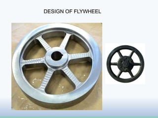
  • 20. Construction of Flywheel Flywheels are typically made of steel and rotate on conventional bearings; these are generally limited to a revolution rate of a few thousand RPM The flywheel of smaller size( upto 600 mm dia )are casted in one piece. The rim and the hub are joined together by means of web.
  • 21. Construction If flywheel is of larger size (upto 2-5 meters diameter ), then it is made of arms. The number of arms depends upon the size of the flywheel and its speed of rotation. But the flywheels above 2-5 meters are usually casted in two pieces. Such a flywheel is known as “ split flywheel “. A split flywheel has the advantage of relieving the shrinkage stresses in the arms due to unequal rates of cooling of casting.
  • 22. DESIGN APPROACH There are two stages to the design of a flywheel. • First, the amount of energy required for the desired degree ofsmoothening must be found and the (mass) moment of inertia needed to absorb that energy determined. • Then flywheel geometry must be defined that caters the required moment of inertia in a reasonably sized package and is safe against failure at the designed speeds of operation. Design Parameters:- • It depend upon acceptable changes in the speed. Speed fluctuation:- • The change in the shaft speed during a cycle is called the speed fluctuation and it is given by Fl =ωmax−ωmin
  • 23. DESIGN OF FLYWHEEL Design Equation:- S I = 𝑬𝒌 𝑪𝒇∗ 𝝎𝒂𝒗𝒈 𝟐 where “Cf”is the co-efficient of speed fluctuation and “Ek”is the kinetic energy and “𝝎avg” is the average rotational motion. Torque Variation and Energy:- The required change in kinetic energy Ek is obtained from the known torque time relation or curve by integrating it for one cycle and it is given by 𝜃@ 𝜔 𝜃@ 𝜔 𝑚 𝑎 𝑥 (𝑇1 −𝑇𝑎𝑣𝑔)d𝜃=Ek
  • 24. GEOMETRY OF FLYWHEEL • It can be a solid cylindrical disc. • It can be like conventional wheel design. But energy requirements and size of the flywheel increases the geometry changes to disc of central hub and peripheral rimconnected by webs and to hollow wheels with multiple arms.
  • 26. GEOMETRY OF FLYWHEEL • For a solid disc geometry with inside radius ri and out side radius ro,the mass moment of inertia I is • The mass of a hollow circular disc of constant thickness tis • Combing the two equations we can write • Where is material’s weight density 
  • 27. STRESSES IN FLYWHEEL • Flywheel being a rotating disc, centrifugal stresses acts upon its distributed mass and attempts to pull it apart. Its effect is similar to those caused by an internally pressurized cylinder. •  = material weight density, ω= angular velocity in rad/sec. ν= Poisson’s ratio, is the radius to a point of interest, ri and ro are inside and outsideradii of the solid disc flywheel.
  • 28. ADVANCE AND MODERN FLYWHEEL • Advanced flywheels are also now used for protecting against interruptions to the national electricity grid. – The flywheel provides power during period between the loss of utility supplied power and either the return of utility power or the start of a sufficient back-up power system • Flywheels have also been proposed as a power booster for electric vehicles. Speeds of 100,000 rpm have been used to achieve very high power densities. • Modern high energy flywheels use composite rotors made with carbon- fibre materials. The rotors have a very high strength-to-density ratio, and rotate at speeds up to 100,000 rpm. in a vacuum chamber to minimize aerodynamic losses.
  • 29. BENEFITS IN AEROSPACE Flywheelsare preferred over conventional batteries in many aerospace applications because of the following benefits: • 5 to 10+ times greater specific energy • Lower mass / kW output • Long life. Unaffected by number of charge / discharge cycles • 85-95% round trip efficiency • Fewer regulators / controls needed • Greater peak load capability • Reduced maintenance / life cycle costs
  • 31. Example 22.1. The turning moment diagram for a petrol engine is drawn to the following scales: Turning moment, 1 mm = 5 N-m; Crank angle, 1 mm = 1º. The turning moment diagram repeats itself at every half revolution of the engine and the areas above and below the mean turning moment line, taken in order are 295, 685, 40, 340, 960, 270 mm2. Determine the mass of 300 mm diameter flywheel rim when the coefficient of fluctuation of speed is 0.3% and the engine runs at 1800 r.p.m. Also determine the cross-section of the rim when the width of the rim is twice of thickness. Assume density of rim material as 7250 kg / m3.