1. CHAPTER 19
CONCRETE AND MECHANICALLY
STABILIZED EARTH RETAINING WALLS
PART A—CONCRETE RETAINING WALLS
19.1 INTRODUCTION
The common types of concrete retaining walls and their uses were discussed in Chapter 11. The
lateral pressure theories and the methods of calculatingthe lateral earth pressures were described in
detail in the same chapter. The two classical earth pressure theories that have been considered are
those of Rankine and Coulomb. In this chapter we are interested in the following:
1. Conditions under which the theories of Rankine and Coulomb are applicable to cantilever
and gravity retaining walls under the active state.
2. The common minimum dimensions used for the two types of retaining walls mentioned
above.
3. Use of charts for the computation of active earth pressure.
4. Stability of retaining walls.
5. Drainage provisions for retaining walls.
19.2 CONDITIONS UNDER WHICH RANKINE AND COULOMB
FORMULAS ARE APPLICABLE TO RETAINING WALLS UNDER
ACTIVE STATE
Conjugate Failure Planes Under Active State
When a backfill of cohesionless soil is under an active state of plastic equilibrium due to the
stretching of the soil mass at every point in the mass, two failure planes called conjugate rupture
833
2. 834 Chapter 19
planes are formed. These are further designated as the inner failure plane and the outer failure
plane as shown in Fig. 19.1. These failure planes make angles of a. and «0 with the vertical. The
equations for these angles may be written as (for a sloping backfill)
a. = +
s-B
-—
2 2
£-J3
"°~ 2 2
. sinytf
where sin s = (19.2)
„ _
when /7=0,
._„
- = 45°-— , an =
2 2 °
yieo
- = 45°- —
2 2
The angle between the two failure planes = 90 - 0 .
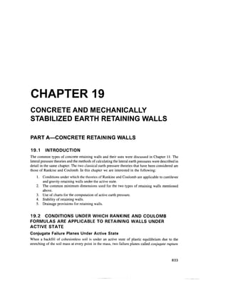
Conditions for the Use of Rankine's Formula
1. Wall should be vertical with a smooth pressure face.
2. When walls are inclined, it should not come in the way of the formation of the outer failure
plane. Figure 19.1 shows the formation of failure planes. Since the sloping face AB' of the
retaining wall makes an angle aw greater than ao, the wall does not interfere with the
formation of the outer failure plane. The plastic state exists within wedge ACC'.
The method of calculating the lateral pressure on AB' is as follows.
1. Apply Rankine's formula for the vertical section AB.
2. Combine P with W , the weight of soil within the wedge ABB', to give the resultant PR.
Let the resultant PR in this case make an angle 8r with the normal to the face of the wall. Let
the maximum angle of wall friction be 8m. If 8r > 8m, the soil slides along the face AB'of the wall.
Outer failure plane ^
Inner failure plane
Figure 19.1 Application of Rankine's active condition to gravity walls
3. Concrete and Mechanically Stabilized Earth Retaining Walls 835
Outer failure plane
Inner failure plane
Figure 19.2 Lateral earth pressure on cantilever walls under active condition
In such an eventuality, the Rankine formula is not recommended but the Coulomb formula may be
used.
Conditions for the Use of Coulomb's Formula
1. The back of the wall must be plane or nearly plane.
2. Coulomb's formula may be applied under all other conditions where the surface of the wall
is not smooth and where the soil slides along the surface.
In general the following recommendations may be made for the application of the Rankine or
Coulomb formula without the introductionof significant errors:
1. Use the Rankine formula for cantilever and counterfort walls.
2. Use the Coulomb formula for solid and semisolid gravity walls.
In the case of cantilever walls (Fig. 19.2), Pa is the active pressure acting on the vertical
section AB passing through the heel of the wall. The pressure is parallel to the backfill surface and
acts at a height H/3 from the base of the wall where H is the height of the section AB. The resultant
pressure PR is obtained by combining the lateral pressure Pa with the weight of the soil Ws between
the section AB and the wall.
19.3 PROPORTIONING OF RETAINING WALLS
Based on practical experience, retaining walls can be proportioned initially which may be checked
for stability subsequently. The common dimensions used for the various types of retaining walls are
given below.
Gravity Walls
A gravity walls may be proportioned in terms of its height given in Fig. 19.3(a). The minimum top
width suggested is 0.30 m. The tentative dimensions for a cantilever wall are given in Fig. 19.3(b)
and those for a counterfort wall are given in Fig. 19.3(c).
4. 836 Chapter 19
0.3m to///12
Min. batter
1 :48
0.3 m min.
H h-
Min. batter
1 :48
*-B =0.5 to 0.7//-*| *
-HO.ltfh— v
= H/8toH/6
I—-B = 0.4 to 0.7#-»-|
= H/l2toH/lO
(a) Gravity wall (b) Cantilever wall
03 W
0.2 m min
(c) Counterfort wall
Fig. 19.3 Tentative dimensions for retaining walls
19.4 EARTH PRESSURE CHARTS FOR RETAINING WALLS
Charts have been developed for estimating lateral earth pressures on retaining walls based on
certain assumed soil properties of the backfill materials. These semi empirical methods represent a
body of valuable experience and summarize much useful information. The charts given in Fig. 19.4
are meant to produce a design of retaining walls of heights not greater than 6 m. The charts have
been developed for five types of backfill materials given in Table 19.1. The charts are applicable to
the following categories of backfill surfaces. They are
1. The surface of the backfill is plane and carries no surcharge
2. The surface of the backfill rises on a slope from the crest of the wall to a level at some
elevation above the crest.
The chart is drawn to represent a concrete wall but it may also be used for a reinforced soil
wall. All the dimensions of the retaining walls are given in Fig. 19.4. The total horizontal and
vertical pressures on the vertical section of A B of height H are expressed as
P, = -K,H2
n <• n (19.3)
5. Concrete and Mechanically Stabilized Earth Retaining Walls 837
Table 19.1 Types of backfill for retaining walls
Type Backfill material
Coarse-grained soil without admixture of fine soil particles,
very permeable (clean sand or gravel)
Coarse-grained soil of low permeability due to
admixture of particles of silt size
Residual soil with stones fine silty sand, and granular
materials with conspicuous clay content
Very soft or soft clay, organic silts, or silty clays
Medium or stiff clay
Note:
Numerals on the curves indicate
soil types as described
in Table 19.1
For materials of type 5
computations of pressure
may be based on the value of H
1 meter less than actual value
10 20
Values of slope angle
40
Figure 19.4 Chart for estimating pressure of backfill against retaining walls
supporting backfills with a plane surface. (Terzaghi, Peck, and Mesri, 1996)
6. H,=0
H
Soil type Soil type 2 Soil type 3
15
10
0.4 0.8 1.0 0 0.4 0.8 1.0 0
Values of ratio H}IH
0.4 0.8 1.0
Figure 19.5 Chart for estimating pressure of backfill against retaining walls supporting backfills with a surface that slopes
upward from the crest of the wall for limited distance and then becomes horizontal. (Terzaghi et al., 1996)
7. Concrete and Mechanically Stabilized Earth Retaining Walls 839
Soil type 4 Soil type 5
JV
25
3
3
> 10
5
n
*
~~
Ma;
K.
c slop
= 0
; 3:1
Note:
Numerals on curves
indicate the following
slopes
No.
1
2
3
4
5
Slope
1.5:1
1.75:1
2:1
3:1
6:1
0 0.2 0.4 0.6 0.8 1.0 0 0.2 0.4 0.6 0.8 1.0
Values of ratio HIH Values of ratio H}/H
Figure 19.5 Continued
PV=-KVH2
(19.4)
Values of Kh and Kv are plotted against slope angle /? in Fig. 19.4 and the ratio HJH in
Fig. 19.5.
19.5 STABILITY OF RETAINING WALLS
The stability of retaining walls should be checked for the followingconditions:
1. Check for sliding
2. Check for overturning
3. Check for bearing capacity failure
4. Check for base shear failure
The minimumfactors of safety for the stabilityof the wall are:
1. Factor of safety against sliding =1.5
2. Factor of safety against overturning= 2.0
3. Factor of safety against bearing capacity failure = 3.0
Stability Analysis
Consider a cantilever wall with a sloping backfill for the purpose of analysis. The same principle
holds for the other types of walls.
Fig. 19.6 gives a cantilever wall with all the forces acting on the wall and the base, where
Pa = active earth pressure acting at a height H/3 over the base on section AB
h a >~^
P = P sin/3
v a "
13 = slope angle of the backfill
8. 840 Chapter 19
Wc
w.
Fr
(a) Forces acting on the wall
-B-
-Key
(b) Provision of key to increase sliding resistance
Figure 19.6 Check for sliding
weight of soil
weight of wall including base
the resultant of Ws and Wc
passive earth pressure at the toe side of the wall.
base sliding resistance
Check for Sliding (Fig. 19.6)
The force that moves the wall = horizontal force Ph
9. Concrete and Mechanically Stabilized Earth Retaining Walls 841
The force that resists the movement is
F Rtan8+P (19.5)
R = total vertical force = Ws + Wc + Pv,
8 = angle of wall friction
ca = unit adhesion
If the bottom of the base slab is rough, as in the case of concrete poured directly on soil, the
coefficient of friction is equal to tan 0, 0 being the angle of internal friction of the soil.
The factor of safety against sliding is
F =-*-> (19.6)
In case Fs < 1.5, additional factor of safety can be provided by constructing one or two keys
at the base level shown in Fig. 19.6b. The passive pressure P (Fig. 19.6a) in front of the wall should
not be relied upon unless it is certain that the soil will always remain firm and undisturbed.
Check for Overturning
The forces acting on the wall are shown in Fig. 19.7. The overturning and stabilizing moments may be
calculated by taking moments about point O. The factor of safety against overturning is therefore
Sum of moments that resist overturning _ MR
Sum of overturning moments M (19.7a)
Figure 19.7 Check for overturning
10. 842 Chapter 19
we may write (Fig. 19.7)
Wl +WI +PB
C C S S V
F =
where F should not be less than 2.0.
(19.7b)
Check for Bearing Capacity Failure (Fig. 19.8)
In Fig. 19.8, W( is the resultant of Ws and Wc. PR is the resultant of Pa and Wf and PR meets the
base at m. R is the resultant of all the vertical forces acting at m with an eccentricity e. Fig. 19.8
shows the pressure distributionat the base with a maximum qt at the toe and a minimum qh at the
heel.
An expression for e may be written as
B ( M R - M 0 )
2 IV
where R =XV= sum of all vertical forces
(19.8a)
Toe
Figure 19.8 Stability against bearing capacity failure
11. Concrete and Mechanically Stabilized Earth Retaining Walls 843
The values of qt and qh may be calculated by making use of the equations
B
B
B (19.8b)
(19.8c)
where, qa = R/B = allowable bearing pressure.
Equation (19.8) is valid for e< B/6. When e = B/6, qt = 2qa and qh = 0. The base width B
should be adjusted to satisfy Eq. (19.8) . When the subsoil below the base is of a low bearing
capacity, the possible alternative is to use a pilefoundation.
The ultimate bearing capacity qu may be determined using Eq. (12.27) taking into account the
eccentricity. It must be ensured that
Base Failure of Foundation (Fig. 19.9)
If the base soil consists of medium to soft clay, a circular slip surface failure may develop as
shown in Fig. 19.9. The most dangerous slip circle is actually the one that penetrates deepest into
the soft material. The critical slip surface must be located by trial. Such stability problems may
be analyzed either by the method of slices or any other method discussed in Chapter 10.
Figure 19.9 Stability against base slip surface shear failure
12. 844 Chapter 19
Drainage Provision for Retaining Walls (Fig.19.10)
The saturation of the backfill of a retaining wall is alwaysaccompanied by a substantialhydrostatic
pressure on the back of the wall. Saturation of the soil increases the earth pressure by increasing the
unit weight. It is therefore essential to eliminate or reduce pore pressure by providing suitable
drainage. Four types of drainage are given in Fig.19.10. The drains collect the water that enters the
backfill and this may be disposed of throughoutlets in the wall called weep holes. The graded filter
material should be properly designed to prevent clogging by fine materials. The present practice is
to use geotextiles or geogrids.
The weep holes are usually made by embedding 100 mm (4 in.) diameter pipes in the wall
as shown in Fig.19.10. The vertical spacing between horizontal rows of weep holes should not
exceed 1.5 m. The horizontal spacing in a given row depends upon the provisions made to
direct the seepage water towards the weep holes.
Percolating
•*- water during
rain
Percolating
water during
Permanently
drained
(c) (d)
Figure 19.10 Diagram showing provisions for drainage of backfill behind retaining
walls: (a) vertical drainage layer (b) inclined drainage layer for cohesionless backfill,
(c) bottom drain to accelerate consolidation of cohesive back fill, (d) horizontal drain
and seal combined with inclined drainage layer for cohesive backfill (Terzaghi et al.,
1996)
13. Concrete and Mechanically Stabilized Earth Retaining Walls 845
Example 19.1
Figure Ex. 19.1(a) shows a section of a cantilever wall with dimensions and forces acting
thereon. Check the stability of the wall with respect to (a) overturning, (b) sliding, and (c)
bearing capacity.
Solution
Check for Rankine's condition
FromEq. (19.1b)
where sinf =
2 2
sin5 sin!5c
sin (j) sin 30°
ore *31°
_ 90-30 31-15
(Xn —
= 0.5176
= 22C
The outer failure line AC is drawn making an angle 22° with the vertical AB. Since this line
does not cut the wall Rankine's condition is valid in this case.
T
// = 0.8+ 7 = 7.8m
/>„
4.75m
FR A I (c- 0) soil
c = 60kN/m2
(/) - 25° y = 19kN/m3
Figure Ex. 19.1(a)
14. 846 Chapter 19
Rankine active pressure
Height of wall = AB = H = 7.8 m (Fig. Ex. 19.l(a))
where K, =tan2
(45°-^ / 2)= -
3
substituting
Pa = - x 18.5 x (7.8)2
x- = 187.6 kN/ mofwall
2 3
Ph = Pacosj3 = 187.6cos 15°= 181.2 kN/m
Pv = Pa sin 0= 187.6 sin 15° = 48.6 kN / m
Check for overturning
The forces acting on the wall in Fig. Ex. 19.1(a) are shown. The overturning and stabilizing
moments may be calculated by taking moments about point O.
The whole section is divided into 5 parts as shown in the figure. Let these forces be
represented by vvp vv2, ... vv5 and the correspondinglever arms as /p /2, ... 15.Assume the weight of
concrete yc = 24 kN/m3
. The equation for the resisting moment is
MR —Wj/j + w2/9 + ... w5/5
The overturning moment is
M0 = .P
h 3
The details of calculations are tabulatedbelow.
Section
No.
1
2
3
4
5
Area
(m2
)
1.20
18.75
3.56
3.13
0.78
Unit weight
kN/m3
18.5
18.5
24.0
24.0
24.0
Weight
kN/m
22.2
346.9
85.4
75.1
18.7
Pv = 48.6
2, = 596.9
Lever
arm(m)
3.75
3.25
2.38
1.50
1.17
4.75
Moment
kN-m
83.25
1127.40
203.25
112.65
21.88
230.85
2W= 1,779.3 = MR
M0= 181.2x2.6 = 471.12 kN-m
F =
MR _ 1,779.3
~M~~ 471.12
- 3.78 > 2.0 --OK.
Check for sliding (Fig. 19.1a)
The force that resists the movement as per Eq. (19.5) is
FR =CaB + R tan 5+ Pp
15. Concrete and Mechanically Stabilized Earth Retaining Walls 847
where B =width = 4.75 m
c
a ~ ac
u' a
~ adhesion factor = 0.55 from Fig. 17.15
R =total vertical force Iv = 596.9 kN
For the foundation soil:
S = angle of wall friction ~ 0 = 25°
FromEq. (11.45c)
where h = 2 m, y= 19 kN/m3
, c = 60 kN/m2
K = tan2
(45° + §12) = tan2
(45° + 25/2) = 2.46
substituting
p =-xl9x22
p
2
.46= 470 kN/m
7m
0.75 mt
e =0.183m
B/2 B/2
Figure Ex. 19.Kb)
16. 848 Chapter 19
= 60 x 4.75 + 596.9 tan 25° + 470 = 285 + 278 + 470 = 1033 kN/m
P= 181.2 kN/m
Ph 181.2
1.5 -OK.
Normally the passive earth pressure Pn is not considered in the analysis. By neglecting Pp, the
factor of safety is
1033- 470
181.2 181.2
_
Check for bearing capacity failure (Fig. 19.Ib)
From Eq. (19.8b and c), the pressures at the toe and heel of the retaining wall may be written as
R
E
1-
B
where e = eccentricity of the total load R (= SV) acting on the base. From Eq. (19.8a), the
eccentricity e may be calculated.
€=
B
2
Now qf =
R 2
596.9 , 6x0.183
4.75
.
1+
4.75
596.9
= 154.7 kN/m2
596.9 . 6x0.183 n ,,1 1 V T / ,
qh = 1 —— = 96.6 kN/m2
4.75 4.75
The ultimate bearing capacity qu may be determined by Eq. (12.27). It has to be
ensured that
where F = 3
17. Concrete and Mechanically Stabilized Earth Retaining Walls 849
PART B—MECHANICALLY STABILIZED EARTH
RETAINING WALLS
19.6 GENERALCONSIDERATIONS
Reinforced earth is a construction material composed of soil fill strengthened by the inclusion of rods,
bars, fibers or nets which interact with the soil by means of frictional resistance. The concept of
strengthening soil with rods or fibers is not new. Throughout the ages attempts have been made to
improve the quality of adobe brick by adding straw. The present practice is to use thin metal strips,
geotextiles, and geogrids as reinforcing materials for the construction of reinforced earth retaining walls.
A new era of retaining walls with reinforced earth was introduced by Vidal (1969). Metal strips were
used as reinforcing material as shown in Fig. 19.11 (a). Here the metal strips extend from the panel back
into the soil to serve the dual role of anchoring the facing units and being restrained through the frictional
stresses mobilized between the strips and the backfill soil. The backfill soil creates the lateral pressure
and interacts with the strips to resist it. The walls are relatively flexible compared to massive gravity
structures. These flexible walls offer many advantages including significant lower cost per square meter
of exposed surface. The variations in the types effacing units, subsequent to Vidal's introduction of the
reinforced earth walls, are many. A few of the types that are currently in use are (Koerner, 1999)
Figure 19.11 (a) Component parts and key dimensions of reinforced earth wall
(Vidal, 1969)
18. 850 Chapter 19
1. Facing panels with metal strip reinforcement
2. Facing panels with wire mesh reinforcement
3. Solid panels with tie back anchors
4. Anchored gabion walls
5. Anchored crib walls
Facing units
Rankine wedge —
H
As required
Reinforcing strips
"•;''•: T!:
•.*.'•-A-: Select fill ;;
.>;'•;.'_..
Original ground
or other backfill
1
(sO.8//) '
(b) Line details of a reinforced earth wall in place
(c) Front face of a reinforced earth wall under constructionfor a bridge approach fill using patented precast
concrete wall face units
Figure 19.1Kb) and (c) Reinforced earth walls (Bowles, 1996)
19. Concrete and Mechanically Stabilized Earth Retaining Walls 851
6. Geotextile reinforced walls
7. Geogrid reinforced walls
In all cases, the soil behind the wall facing is said to be mechanically stabilized earth (MSE)
and the wall system is generally called an MSE wall.
The three components of a MSE wall are the facing unit, the backfill and the reinforcing
material. Figure 19.11(b) shows a side view of a wall with metal strip reinforcement and
Fig. 19.1l(c) the front face of a wall under construction (Bowles, 1996).
Modular concrete blocks, currently called segmental retaining walls (SRWS, Fig. 19.12(a))
are most common as facing units. Some of the facing units are shown in Fig. 19.12. Most
interesting in regard to SRWS are the emerging block systems with openings, pouches, or planting
areas within them. These openings are soil-filled and planted with vegetation that is indigenous to
the area (Fig. 19.12(b)). Further possibilities in the area of reinforced wall systems could be in the
use of polymer rope, straps, or anchor ties to the facing in units or to geosynthetic layers, and
extending them into the retained earth zone as shown in Fig. 19.12(c).
A recent study (Koerner 2000) has indicated that geosynthetic reinforced walls are the least
expensive of any wall type and for all wall height categories (Fig. 19.13).
19.7 BACKFILL AND REINFORCING MATERIALS
Backfill
The backfill, is limited to cohesionless, free draining material (such as sand), and thus the key
properties are the density and the angle of internal friction.
Facing
system
(varies)
Block system
with openings
for vegetation
iK&**¥$r$k
l)fr^$ffi:™:.fo:
•v'fo.'j;
?ffij?.i
yfcX'r
(a) Geosynthetic reinforced wall (b) Geosynthetic reinforced "live wall"
Polymer ropes
or stra
Ps
Soil anchor Rock anchor
(c) Future types of geosyntheticanchorage
Figure 19.12 Geosynthetic use for reinforced walls and bulkheads (Koerner, 2000)
20. 852 Chapter 19
900
800-
700-
|600H
c3
? SCO-
'S
§ 400-
U
300-
200-
1004
1 2 3 4 5 6 7 8 9 10 11 12 13
Height of wall (m)
Figure 19.13 Mean values of various categories of retaining wall costs
(Koerner, 2000)
Reinforcing material
The reinforcements may be strips or rods of metal or sheets of geotextile, wire grids or geogrids
(grids made from plastic).
Geotextile is a permeable geosynthetic comprised solely of textiles. Geotextiles are used with
foundation soil, rock, earth or any other geotechnical engineering-related material as an integral
part of a human made project, structure, or system (Koerner, 1999). AASHTO (M288-96) provides
(Table 19.2) geotextile strength requirements (Koerner, 1999). The tensile strength of geotextile
varies with the geotextile designation as per the design requirements. For example, a woven slit-
film polypropylene (weighing 240 g/m2
) has a range of 30 to 50 kN/m. The friction angle between
soil and geotextiles varies with the type of geotextile and the soil. Table 19.3gives values of
geotextile friction angles (Koerner, 1999).
The test properties represent an idealized condition and therefore result in the maximum
possible numerical values when used directly in design. Most laboratory test values cannot
generally be used directly and must be suitably modified for in-situ conditions. For problems
dealing with geotextiles the ultimate strength TU should be reduced by applying certain reduction
factors to obtain the allowable strength Ta as follows (Koerner, 1999).
T =T
I
RFID x RFCR x RFCD x RFBD
(19.9)
where
RF
CR =
RF
BD =
RF
CD =
allowable tensile strength
ultimate tensile strength
reduction factor for installation damage
reduction factor for creep
reduction factor for biological degradation and
reduction factor for chemical degradation
Typical values for reduction factors are given in Table19.4.
21. Table 19.2 AASHTO M288-96 Geotextile strength property requirements
Geotextile Classification* tt
Case 1
strength
seam
gth $
trength
ure strength
strength
Test Units
methods
ASTM N
D4632
ASTM N
D4632
ASTM N
D4533
ASTM N
D4833
ASTM kPa
D3786
Elongation
< 50 %
1400
1200
500
500
3500
Elongation
> 50 %
900
810
350
350
1700
Case 2
Elongation
< 50 %
1100
990
400
400
2700
Elongation
> 50 %
700
630
250
2505
1300
Case 3
Elongation
< 50 %
800
720
300
300
2100
Elongation
>50 %
500
450
180
180
950
measured in accordance with ASTM D4632. Woven geotextiles fail at elongations (strains)< 50%, while nonwovens fail at elongation (strains) > 50%.
When sewnseams are required. Overlap seam requirements are application specific.
required MARV tear strength for woven monofilament geotextiles is 250 N.
22. 854 Chapter 19
Table 19.3 Peak soil-to-geotextile friction angles and efficiencies in selected
cohesionless soils*
Geotextile type
Woven, monofilament
Woven, slit-film
Nonwoven, heat-bonded
Nonwoven, needle-punched
Concrete sand
(0 = 30°)
26° (84 %)
24°(77%)
26° (84 %)
30° (100%)
Rounded sand
(0 = 28°)
-
24° (84 %)
-
26° (92 %)
Silty sand
(0 - 26°)
-
23° (87 %)
-
25° (96 %)
* Numbers in parentheses are the efficiencies. Values such as these should not be used in final design. Site
specific geotextiles and soils must be individually tested and evaluated in accordance with the particular
project conditions: saturation, type of liquid, normal stress, consolidation time, shear rate, displacement
amount, and so on. (Koerner,1999)
Table 19.4 Recommended reduction factor values for use in [Eq. (19.9)]
Range of Reduction Factors
Application
Area
Separation
Cushioning
Unpaved roads
Walls
Embankments
Bearing capacity
Slope stabilization
Pavement overlays
Railroads (filter/sep.)
Flexible forms
Silt fences
Installation
Damage
1.1 to
1.1 to
1.1 to
1.1 to
1.1 to
1.1 to
1.1 to
1.1 to
1.5 to
1.1 to
1.1 to
2
2,
2,
2,
2,
.5
.0
.0
.0
.0
2.0
1.
1,
3,
1.
1.
.5
.5
.0
,5
.5
Creep*
1
1
1
2,
2,
.5 to
.2 to
.5 to
.Oto
.Oto
2,
1
2
4.
3,
.5
.5
.5
.0
.5
2.0 to 4.0
2.
1
1
1.
1
.Oto
.Oto
.Oto
.5 to
.5 to
3.
2,
1.
3.
2,
,0
,0
,5
,0
.5
Chemical
Degradation
1.0 to
1.0 to
1.0 to
1.0 to
1.0 to
1.0 to
1.0 to
1.0 to
1.5 to
1.0 to
1.0 to
1.5
2.0
1.5
1.5
1.5
1.5
1.5
1.5
2.0
1.5
1.5
Biological
Degradation
1.0 to
1.0 to
1.0 to
1.0 to
1.0 to
1.0 to
1.0 to
1.0 to
1.0 to
1.0 to
1.0 to
1.2
1.2
1.2
1.3
1.3
1.3
1.3
1.1
1.2
1.1
1.1
* The low end of the range refers to applications which have relatively short service lifetimes and / or
situations where creep deformationsare not critical to the overall system performance. (Koerner, 1999)
Table 19.5 Recommended reduction factor values for use in Eq. (19.10) for
determining allowable tensile strength of geogrids
Application Area
Unpaved roads
Paved roads
Embankments
Slopes
Walls
Bearing capacity
DC DC
Hh
/D hh
C/?
1.1
1.2
1.1
1.1
1.1
1.2
to
to
to
to
to
to
1.6
1.5
1.4
1.4
1.4
1.5
1.5 to
1.5 to
2.0 to
2.0 to
2.0 to
2.0 to
2,
2.
3,
3,
3,
3,
.5
.5
.0
.0
.0
.0
R
f~CD *" B£>
1.0
1.1
1.1
1.1
1.1
1.1
to
to
to
to
to
to
1.5
1.6
1.4
1.4
1.4
1.6
1.0 to
1.0 to
1.0 to
1.0 to
1.0 to
1.0 to
1.1
1.1
1.2
1.2
1.2
1.2
23. Concrete and Mechanically Stabilized Earth Retaining Walls 855
Geogrid
A geogrid is defined as a geosynthetic material consisting of connected parallel sets of tensile ribs
with apertures of sufficient size to allow strike-through of surrounding soil, stone, or other
geotechnical material (Koerner, 1999).
Geogrids are matrix like materials with large open spaces called apertures, which are
typically 10 to 100 mm between the ribs, called longitudinal and transverse respectively. The
primary function of geogrids is clearly reinforcement. The mass of geogrids ranges from 200 to
1000 g/m2
and the open area varies from 40 to 95 %. It is not practicable to give specific values for
the tensile strength of geogrids because of its wide variation in density. In such cases one has to
consult manufacturer's literature for the strength characteristics of their products. The allowable
tensile strength, Ta, may be determined by applying certain reduction factors to the ultimate
strength TU as in the case of geotextiles. The equation is
rri _ rri
~
The definition of the various terms in Eq (19.10) is the same as in Eq. (19.9). However, the
reduction factors are different. These values are given in Table 19.5 (Koerner, 1999).
Metal Strips
Metal reinforcement strips are available in widthsranging from 75 to 100 mm and thickness on the
order of 3 to 5 mm, with 1 mm on each face excluded for corrosion (Bowles, 1996). The yield
strength of steel may be taken as equal to about 35000 lb/in2
(240 MPa) or as per any code of
practice.
19.8 CONSTRUCTION DETAILS
The method of construction of MSE walls depends upon the type effacing unit and reinforcing
material used in the system. The facing unit which is also called the skin can be either flexible
or stiff, but must be strong enough to retain the backfill and allow fastenings for the
reinforcement to be attached. The facing units require only a small foundation from which they
can be built, generally consisting of a trench filled with mass concrete giving a footing similar
to those used in domestic housing. The segmental retaining wall sections of dry-laid masonry
blocks, are shown in Fig. 19.12(a). The block system with openings for vegetation is shown in
Fig. 19.12(b).
The construction procedure with the use of geotextiles is explained in Fig. 19.14(a). Here, the
geotextile serve both as a reinforcement and also as a facing unit.The procedure is described below
(Koerner, 1985) with reference to Fig. 19.14(a).
1. Start with an adequate working surface and staging area (Fig. 19.14a).
2. Lay a geotextile sheet of proper width on the ground surface with 4 to 7 ft at the wall face
draped over a temporary wooden form (b).
3. Backfill over this sheet with soil. Granular soils or soils containing a maximum 30 percent
silt and /or 5 percent clay are customary (c).
4. Construction equipment must work from the soil backfill and be kept off the unprotected
geotextile. The spreading equipment should be a wide-tracked bulldozer that exerts little
pressure against the ground on which it rests. Rolling equipment likewise should be of
relatively light weight.
24. 856 Chapter 19
Temporary
wooden form
(a) (b)
/?^/2xs/^/
(c)
C
(e) (f)
(g) (h)
Figure 19.14(a) General construction procedures for using geotextiles in fabric
wall construction (Koerner, 1985)
5. When the first layer has been folded over the process should be repeated for the second
layer with the temporary facing form being extended from the original ground surface or
the wall being stepped back about 6 inches so that the form can be supported from the first
layer. In the latter case, the support stakes must penetrate the fabric.
6. This process is continued until the wall reaches its intended height.
7. For protection against ultraviolet light and safety against vandalism the faces of such walls
must be protected. Both shotcrete and gunite have been used for this purpose.
Figure 19.14(b) shows complete geotextile walls (Koerner, 1999).
25. Concrete and Mechanically Stabilized Earth Retaining Walls 857
Figure 19.14(b) Geotextile walls (Koerner, 1999)
19.9 DESIGN CONSIDERATIONS FOR A MECHANICALLY
STABILIZED EARTHWALL
The design of a MSE wall involves the following steps:
1. Check for internal stability, addressing reinforcement spacing and length.
2. Check for external stability of the wall against overturning, sliding, and foundation failure.
The general considerations for the design are:
1. Selection of backfill material: granular, freely draining material is normally specified.
However, with the advent of geogrids, the use of cohesive soil is gaining ground.
2. Backfill should be compacted with care in order to avoid damage to the reinforcing
material.
3. Rankine's theory for the active state is assumed to be valid.
4. The wall should be sufficiently flexible for the development of active conditions.
5. Tension stresses are considered for the reinforcement outside the assumed failure zone.
6. Wall failure will occur in one of three ways
26. r
-z)
Surcharge
lie / '
(90-0)= 45° -0/2
Failure plane
45°
(a) Reinforced earth-wall profile with surcharge load
h- * -H
(b) Lateral pressure distribution diagrams
Figure 19.15 Principles of MSE wall design
27. Concrete and Mechanically Stabilized Earth Retaining Walls 859
Reinforcement
Figure 19.16 Typical range in strip reinforcement spacing for reinforced earth
walls (Bowles, 1996)
a. tension in reinforcements
b. bearing capacity failure
c. sliding of the whole wall soil system.
7. Surcharges are allowed on the backfill. The surcharges may be permanent (such as a
roadway) or temporary.
a. Temporary surcharges within the reinforcement zone will increase the lateral pressure
on the facing unit which in turn increases the tension in the reinforcements, but does not
contribute to reinforcement stability.
b. Permanent surcharges within the reinforcement zone will increase the lateral pressure
and tension in the reinforcement and will contribute additional vertical pressure for the
reinforcement friction.
c. Temporary or permanent surcharges outside the reinforcement zone contribute lateral
pressure which tends to overturn the wall.
8. The total length L of the reinforcement goes beyond the failure plane AC by a length Lg.
Only length Lg (effective length) is considered for computing frictional resistance. The
length LR lying within the failure zone will not contribute for frictional resistance
(Fig. 19.15a).
9. For the propose of design the total length Lremains the same for the entire height of wall H.
Designers, however, may use their discretion to curtail the length at lower levels. Typical
ranges in reinforcement spacing are given in Fig. 19.16.
19.10 DESIGN METHOD
The following forces are considered:
1. Lateral pressure on the wall due to backfill
2. Lateral pressure due to surcharge if present on the backfill surface.
28. 860 Chapter 19
3. The vertical pressure at any depth z on the strip due to
a) overburden pressure po only
b) overburden pressure po and pressure due to surcharge.
Lateral Pressure
Pressure due to Overburden
Lateral earth pressure due to overburden
At depth z Pa = POZKA = yzKA (19.11a)
Atdepthtf Pa=poHKA=yHKA (19. lib)
Total active earth pressure
p =-vH2
K. (19.12)
a 2 ^
Pressure Due to Surcharge (a) of Limited Width, and (b) Uniformly Distributed
(a) From Eq. (11.69)
/•^
^ =-^-(/?-sin/?cos2a) (19.13a)
n
(b) qh =qsKA (19.13b)
Total lateral pressure due to overburden and surcharge at any depth z
+qh) (19.14)
Vertical pressure
Vertical pressure at any depth z due to overburden only
P0=rz (19.15a)
due to surcharge (limited width)
(19.15b)
where the 2:1 (2 vertical : 1 horizontal) method is used for determining Ag at any depth z.
Total vertical pressure due to overburden and surcharge at any depth z.
(19.15C)
Reinforcement and Distribution
Three types of reinforcements are normally used. They are
1. Metal strips
2. Geotextiles
3. Geogrids.
29. Concrete and Mechanically Stabilized Earth Retaining Walls 861
Galvanized steel strips of widths varying from 5 to 100mm and thickness from 3 to 5 mm are
generally used. Allowance for corrosion is normally made while deciding the thickness at the rate
of 0.001 in. per year and the life span is taken as equal to 50 years. The vertical spacing may range
from 20 to 150 cm ( 8 to 60 in.) and can vary with depth. The horizontal lateral spacing may be on
the order of 80 to 150 cm (30 to 60 in.). The ultimate tensile strength may be taken as equal to 240
MPa (35,000 lb/in.2
). A factor of safety in the range of 1.5 to 1.67 is normally used to determine the
allowable steel strength fa.
Figure 19.16 depicts a typical arrangement of metal reinforcement. The properties of
geotextiles and geogrids have been discussed in Section 19.7.However, with regards to spacing,
only the vertical spacing is to be considered. Manufacturers provide geotextiles (or geogrids) in
rolls of various lengths and widths. The tensile force per unit width must be determined.
Length of Reinforcement
From Fig. 19.15(a)
L = LR +Le = LR+L{+L2 (19.16)
where LR = (H- z) tan(45° - 0/2)
Le = effective length of reinforcement outside the failure zone
Lj = length subjected to pressure (p0 +Ag) = po
L2 = length subjected to po only.
Strip Tensile Force at any Depth z
The equation for computing T is
T =phxhxs/stnp =(KKA+qh)hxs (19.17a)
The maximum tie force will be
T(max)=(yHKA+qhH)hxs (19.17b)
where ph = yzKA+qh
qh = lateral pressure at depth z due to surcharge
<*hH = ^ at depth//
h = vertical spacing
s = horizontal spacing
where Pa = l/2yff-KA —Rankine's lateral force
P = lateral force due to surcharge
(19.18)
Frictional Resistance
In the case of strips of width b both sides offer frictional resistance. The frictional resistance FR
offered by a strip at any depth z must be greater than the pullout force T by a suitable factor of
safety. We may write
FR=2b[(p0+bq)Ll+p0L2]tanS<TFs (19.19)
or FR =2b[p0Ll+poL2]tanS<TFs (19.20)
where F may be taken as equal to 1.5.
30. 862 Chapter 19
The friction angle 8 between the strip and the soil may be taken as equal to 0 for a rough strip
surface and for a smooth surface 8 may lie between 10 to 25°.
Sectional Area of Metal Strips
Normally the width b of the strip is assumed in the design. The thickness t has to be determined
based on T (max) and the allowable stressfa in the steel. If/ is the yield stress of steel, then
/v
Normally F^ (steel) ranges from 1.5 to 1.67. The thickness t may be obtained from
T(max)
t = (19.22)
The thickness of t is to be increased to take care of the corrosion effect. The rate of corrosion
is normally taken as equal to 0.001 in/yr for a life span of 50 years.
Spacing of Geotextile Layers
The tensile force T per unit width of geotextile layer at any depth z may be obtained from
T = phh = (yzKA+qh)h (19.23)
where qh = lateral pressure either due to a stripload or due to uniformly distributed surcharge.
The maximum value of the computed T should be limited to the allowable value Ta as per
Eq. (19.9). As such we may write Eq. (19.23) as
Ta=TFs=(yzKA+qh)hFs (19.24)
T T
or h=
where F^ = factor of safety (1.3 to 1.5) when using Ta.
Equation (19.25) is used for determining the vertical spacing of geotextile layers.
Frictional Resistance
The frictional resistance offered by a geotextile layer for the pullout force Ta may be expressed as
TaFs (19.26)
Equation (19.26) expresses frictional resistance per unit width and both sides of the sheets are
considered.
Design with Geogrid Layers
A tremendous number of geogrid reinforced walls have been constructed in the past 10 years (Koerner,
1999). The types of permanent geogrid reinforced wall facings are as follows (Koerner, 1999):
1. Articulated precast panels are discrete precast concrete panels with inserts for attaching the
geogrid.
2. Full height precast panels are concrete panels temporarily supported until backfill is complete.
3. Cast-in-place concrete panels are often wrap-around walls that are allowed to settle and,
after 1/2 to 2 years, are covered with a cast-in-place facing panel.
31. Concrete and Mechanically Stabilized Earth Retaining Walls 863
4. Masonry blockfacing walls are an exploding segment of the industry with many different
types currently available, all of which have the geogrid embedded between the blocks and
held by pins, nubs, and/or friction.
5. Gabion facings are polymer or steel-wire baskets filled with stone, having a geogrid held
between the baskets and fixed with rings and/or friction.
The frictional resistance offered by a geogrid against pullout may be expressed as (Koerner,
1999)
(19.27)
where C. = interaction coefficient = 0.75 (mayvary)
Cr = coverage ratio = 0.8 (may vary)
All the other notations are already defined.The spacing of geogrid layers may be obtained from
Ph
where ph = lateral pressure per unit length of wall.
19.11 EXTERNAL STABILITY
The MSB wall system consists of three zones. Thye are
1. The reinforced earth zone.
2. The backfill zone.
(19.28)
Backfill H
(a) Overturning considerations
B
c - co Backfill
(b) Sliding considerations
Wall
Backfill
Foundation soil
(c) Foundation considerations
Figure 19.17 External stability considerations for reinforced earth walls
32. 864 Chapter 19
3. The foundation soil zone.
The reinforced earth zone is considered as the wall for checking the internal stability whereas
all three zones are considered for checking the external stability.The soils of the first two zones are
placed in layers and compacted whereas the foundation soil is a normal one. The properties of the
soil in each of the zones may be the same or different. However, the soil in the first two zones is
normally a free draining material such as sand.
It is necessary to check the reinforced earth wall (width = B) for external stability which
includes overturning, sliding and bearing capacity failure. These are illustrated in Fig. 19.17. Active
earth pressure of the backfill acting on the internal face AB of the wall is taken in the stability
analysis. The resultant earth thrust Pa is assumed to act horizontally at a height H/3 above the base
of the wall. The methods of analysis are the same as for concrete retaining walls.
Example 19.2
A typical section of a retaining wall with the backfill reinforced with metal strips is shown in
Fig. Ex. 19.2. The following data are available:
Height H = 9 m; b = 100 mm; t = 5 mmfy = 240 MPa; Fs for steel = 1.67; Fs on soil friction
= 1.5; 0=36°; 7= 17.5 kN/m3
; 5 = 25°;/? x s = 1 x 1m.
Required:
(a) Lengths L and Le at varying depths.
(b) The largest tension Tin the strip.
(
u
•
2
3
4
9m 5
6
7
3m 8
9
V O
o r
110.5 m
/
' /
/
ll
'^-- Failure plane /
/i = 1 m .^*^ /
/'
7
f
Wall / /
/ / Metal
/////^
Backfill
0 =36°
y= 17.5kN/m3
/ / sinps
Sand / v
' y=l7.5kN/m3
^^^-100 mmx 5 mm
^ £2 , - 36o ' ^— Stepped
' ^ / remtorcen
' Hktrihntin
• /
G
-^m
/ * Linear var
/ ,21 ,_,., ot length c
^ ' -i ^ 1-1-1 •- /
//X
63° i
0.5 m
lent
n (1)
iation
)f strips (2)
Well footing = 36° y = 17.5 kN/m3
Figure Ex. 19.2
33. Concrete and Mechanically Stabilized Earth RetainingWalls 865
(c) The allowable tension in the strip.
(d) Check for external stability.
Solution
From Eq. (19.17a), the tension in a strip at depth z is
T=YzKAshforqh =Q
where y= 17.5 kN/m3
, KA =tan2
(45° - 36/2) = 0.26, s = 1m;h = 1m.
Substituting
T= 17.5 x 0.26 (1) [1]i =4.55z kN/strip.
FST 1.5x4.55z
L = --- = - = 4.14m
e
2yzbtanS 2xl7.5xO.lxO.47xz
This shows that the length Lg = 4.14 m is a constant with depth. Fig. Ex. 19.2 shows the
positions of Lg for strip numbers 1,2 ... 9. The first strip is located 0.5 m below the backfill surface
and the 9th at 8.5 m below with spacings at 1 m apart. Tension in each of the strips may be obtained
by using the equation T = 4.55 z. The total tension ^LT as computed is
Zr = 184.29 kN/m since s = 1m.
As a check the total active earth pressure is
p =~yH2
K. =-17.5 x92
x0.26 = 184.28 kN/m = £7
a
2 A
2
The maximum tension is in the 9th strip, that is, at a depth of 8.5 m below the backfill surface.
Hence
T= YZ KAsh = 17.5 x 8.5 x 0.26 x 1 x 1 = 38.68 kN/strip
The allowable tension is
740 v 103
where fa = = 143.7 x 10³
kN / m2
1.67
Substituting Ta = 143.7 x 103
x 0.005 x 0.1 » 72 kN > T- OK.
The total length of strip L at any depth z is
L =LR +Le = (H-z) tan (45- 0/2) + 4.14 = 0.51 (9- z)+ 4.14 m
where H = 9 m.
The lengths as calculated have been shown in Fig. Ex. 19.2. It is sometimes convenient to use
the same length L with depth or stepped in two or more blocks or use a linear variation as shown in
the figure.
Check for External Stability
Check of bearing capacity
It is necessary to check the base of the wall with the backfill for the bearing capacity per unitlength
of the wall. The width of the wall may be taken as equal to 4.5 m (Fig. Ex. 19.2). The procedure as
explained in Chapter 12 may be followed. For all practical purposes, the shape, depth, and
inclination factors may be taken as equal to 1.
34. 866 Chapter 19
Check for sliding resistance
Sliding resistance F^
F =
Driving force Pa
where FK =Wtan 8 =4
'5+8
'5
x 17.5 x 9tan 36°
K
2
= 1024 x 0.73 = 744 kN
where 8 = 0 = 36° for the foundation soil, and W - weight of the reinforced wall
Pa= 184.28 kN
744
F =— = 4>1.5 --OK
s
184.28
Check for overturning
F
M
«
F
<™
O
From Fig.Ex. 19.2 taking moments of all forces about O, we have
M^=4.5x9xl7.5x — +-x9x (8.5-4.5)(4.5 +-)x 17.5
= 1595+ 1837 = 3432 kN-m
M =P x — = 184.28x- = 553kN-m
0 a
3 3
3432
F = — = 62>2-OK
5
553
Example 19.3
A section of a retaining wall with a reinforced backfill is shown in Fig. Ex. 19.3.The backfill
surface is subjected to a surcharge of 30 kN/m2
. Required:
(a) The reinforcement distribution.
(b) The maximum tension in the strip.
(c) Check for external stability.
Given: b = 100 mm, t = 5 mm,/fl = 143.7MPa, c = 0, 0 = 36°, 8 = 25°, y = 17.5 kN/m3
,
s = 0.5 m, and h = 0.5 m.
Solution
FromEq. (19.17a)
where y= 17.5kN/m3
, KA = 0.26, Ac = h x s = (0.5x 0.5)m2
FromEq. (19.13a)
2
<7f rn
qh =
n
35. Concrete and Mechanically Stabilized Earth Retaining Walls 867
,
H =A
;
1
2
1.75m
3
-*— 4
k5m 5
6
7
8
9
" 1111 *• •" i in —i
A B
1 i • i ' ' i ' i
0.25m / / ,''*,' ,, ° /^<S //S$
* / / xx' ; • 7i
0.5m / / ,' /
* / /
' ' 1 •> T n^^tr.n ilJL.i i
/ / ' / •I
2 rJacKlm saiiu
-^sK' / 2
^
/ ^" ' » r
//>' 0=19.07° / 3
x
//x
a = 29.74° ^- Failure plane
*- LJ?=1.4m -H^- L
iI^475m
-H
Sand / r - „- -
/
1
* y - 17 5lb/ft3
27° / 1.5m 0 = 36°
""~^/
„ 6 = 25°(for thestrips')
745° +0/2 = 63° J
/' ,• 0.25m*
'/////A t
Figure Ex. 19.3
Refer to Fig. E. 19.3 for the definition of a and )S.
^ = 30kN/m2
The procedure for calculating length L of the strip for one depth z = 1.75 m (strip number 4)
is explained below. The same method is valid for the other strips.
Strip No. 4. Depth z = 1.75 m
Pa =YzKA= 17.5 xl.75x 0.26 = 7.96 kN/m2
From Fig. Ex. 19.3, 0= 19.07° = 0.3327 radians
a= 29.74°
fl == 30 kN/m2
2x30
3.14
[0.
0.3327- sin 19.07° cos59.5° = 3.19 kN/m
Figure Ex. 19.3 shows the surcharge distribution at a 2 (vertical) to 1 (horizontal) slope. Per
the figure at depth z = 1.75 m, Ll = 1.475 m from the failure line and LR =(H- z) tan (45° - 0/2)
= 2.75 tan (45° - 36°/2) = 1.4m from the wall to the failure line. It is now necessary to determine L2
(Refer to Fig. 19.15a).
36. 868 Chapter 19
Now T= (7.96 + 3.19) x 0.5 x 0.5 = 2.79 kN/strip.
The equation for the frictional resistance per strip is
FR = 2b (yz + Aq) L{ tan 8 + (yz L2 tan 8) 2b
From the 2:1 distribution Ag at z = 1.75 m is
A? = -£- =-^-=10.9 kN/m2
B +z 1 + 1.75
/?0 = 17.5xl.75 = 30.63 kN/m2
Hence po = 10.9 + 30.63 = 41.53 kN/m2
Now equating frictional resistance FR to tension in the strip with Fs = 1.5, we have
FR-1.5 T. Given b - 100 mm.Nowfrom Eq.(19.20)
FR = 2btanS(poLl +poL2) = 1.5T
Substituting and taking 8 = 25°, we have
2x 0.1x 0.47 [41.53x 1.475 + 30.63 L2] = 1.5x2.79
Simplifying
L2 = -0.546 m-0
Hence Le =L{ +0 = 1.475 m
L =LR +Le=l.4+ 1.475 = 2.875 m
L can be calculated in the same way at other depths.
Maximum tension T
The maximum tension is in strip number 9 at depth z = 4.25m
Allowable Ta =fabt = 143.7 x 103
x 0.1 x 0.005 = 71.85 kN
T = (yzKA+qh)sh
where yzKA
= 17
-50 x 4
-25 x
°-26
= 19
-34 kN/m2
qh = 0.89 kN/m2
from equation for qh at depth z = 4.25m.
Hence T= (19.34 + 0.89) x 1/2x 1/2= 5.05 kN/strip < 71.85 kN - OK
Example 19.4 (Koerner, 1999)
Figure Ex. 19.4shows a section of a retaining wall with geotextile reinforcement. The wall is
backfilled with a granular soil having 7=18 kN/m3
and 0= 34°.
A woven slit-film geotextile with warp (machine) direction ultimate wide-width strength of
50 kN/m and having 8= 24° (Table 19.3) is intended to be used in its construction.
The orientation of the geotextile is perpendicular to the wall face and the edges are to be
overlapped to handle the weft direction. A factor of safety of 1.4 is to be used along with site-
specific reduction factors (Table 19.4).
Required:
(a) Spacing of the individual layers of geotextile.
(b) Determination of the length of the fabric layers.
37. Concrete and MechanicallyStabilized Earth Retaining Walls 869
4 m
Layer No.
1.8m
..(
3 --
4..
2.1m 5
"
r
= 6m
9 - -
10--
11 -•
12 ••
13 --
14--
t * | * t ~F
Reinforced
earth wall
y= 18 kN/m3
~
0 = 36°,d =24°
T
i nv
c
w,
//A //AVS ^
Foundation soil
y= 18.0kN/m3
H 2 m
0 = 34°,d =25.5°
(a) Geotextile layers
Figure Ex. 19.4
pa = 30.24 kN/m2
(b) Pressuredistribution
(c) Check the overlap.
(d) Check for external stability.
The backfill surface carries a uniform surcharge dead load of 10 kN/m2
Solution
C7UIUUUII
(a) The lateral pressure ph at any depth z is expressed as
where pa = yzKA,qh =q KA, KA =tan2
(45° - 36/2) = 0.26
Substituting
ph = 18 x 0.26 z + 0.26 x 10 = 4.68 z + 2.60
From Eq. (19.9), the allowable geotextile strength is
T =T
a U RF
ID X RF
CR X RF
CD X RF
BD
= 50
1
1.2x2.5x1.15x1.1
= 13.2 kN/m
38. 870 Chapter 19
From Eq. (19.17a), the expression for allowable stress in the geotextile at any depth z may be
expressed as
T
h =—-
where h = vertical spacing (lift thickness)
Ta = allowable stress in the geotextile
ph = lateral earth pressure at depth z
Fs = factor of safety = 1.4
Now substituting
13.2 13.2
h =
[4.68(z) + 2.60]1.4 6.55(z) + 3.64
13 2
At z = 6m, h= ' =0.307 m or say 0.30 m
6.55x6 + 3.64
13 2
At / = 33m h = -'-- = 0.52 mor say0.50m
~ —'•*•' "M , _ _. _ _ _ ,. . j
6.55x3.3 + 3.64
13.2
At z = 1 3m h = -:
- = 1.08 m, butuse0.65 m fora suitable distribution.
6.55x1.3+ 3.64
The depth 3.3 m or 1.3 m are used just as a trial and error process to determine suitable
spacings. Figure Ex. 19.4 shows the calculated spacings of the geotextiles.
(b) Length of the Fabric Layers
From Eq. (19.26) we may write
L = s s = . 2.60)1.4 =
e
2xl8ztan24° ~ e
~
From Fig. (19.15) the expression for LR is
LR=(H- z) tan(45° - ^/2) = (H-z) tan(45° - 36/2) =(6.0 - z)(0.509)
The total length L is
39. Concrete and Mechanically Stabilized Earth Retaining Walls 871
The computed L and suggested L are given in a tabular form below.
Layer No
1
2
3
4
5
6
7
8
9
10
11
12
13
14
15
Depth z
(m)
0.65
1.30
1.80
2.30
2.80
3.30
3.60
3.90
4.20
4.50
4.80
5.10
5.40
5.70
6.00
Spacing h
(m)
0.65
0.65
0.50
0.50
0.50
0.50
0.30
0.30
0.30
0.30
0.30
0.30
0.30
0.30
0.30
Le
(m)
0.49
0.38
0.27
0.26
0.25
0.24
0.14
0.14
0.14
0.14
0.14
0.14
0.14
0.14
0.13
Le (min)
(m)
1.0
1.0
1.0
1.0
1.0
1.0
1.0
1.0
1.0
1.0
1.0
1.0
1.0
1.0
1.0
LR
(m)
2.72
2.39
2.14
1.88
1.63
1.37
1.22
1.07
0.92
0.76
0.61
0.46
0.31
0.15
0.00
L (cal)
(m)
3.72
3.39
3.14
2.88
2.63
2.37
2.22
2.07
1.92
1.76
1.61
1.46
1.31
1.15
1.00
L (suggested)
(m)
4.0
-
-
3.0
-
-
-
-
2.0
-
-
-
-
-
-
It may be noted here that the calculated values of Lg are very small and a minimum value of
1.0 m should be used.
(c) Check for the overlap
When the fabric layers are laid perpendicular to the wall, the adjacent fabric should overlap a
length Lg. The minimum value of Lo is 1 .Om. The equation for Lo may be expressed as
L =
/i[4.68(z) + 2.60]1.4
4xl8(z)tan24°
The maximum value of Lo is at the upper layer at z = 0.65. Substituting for z we have
0.65 [4.68(0.65) +2.60] 1.4 n „c
La = = 0.25 m
4 x 18(0.65) tan24°
Since this value of Lo calculated is quite low,use Lo = 1.0mfor all the layers.
(d) Check for external stability
The total active earth pressure Pa is
P =-yH2
KA =-x 18x62
x0.28 = 90.7 kN/m
a
2 A
2
Resisting moment MR W{ /j + W212 +W3 /3 + P14
A< ™ ...H..—.. in ..i ™ i... H i ..-.-
5
Driving moment Mo
p
a(H
/3)
where Wl = 6 x 2 x 18 = 216 kN and /, = 2/2 = 1m
W2 =(6- 2.1)x (3 - 2) (18)= 70.2kN, and 12 = 2.5m
W3 = (6 - 4.2)(4 -3) (18) = 32.4kN and /3 = 3.5m
40. 872 Chapter 19
_ ^ o
— Z. I o > 2. — L/IS.
90.7 x (2)
Check for sliding
Total resistingforce FR
Total driving force Fd
FR = wi + W2 +W
= (216 + 70.2 + 32.4)tan 25.5°
= 318.6x0.477= 152 kN
F, = P = 90.7 kN
a n
152
Hence F = - =1.68 > 1.5 -OK
5
90.7
Check for a foundation failure
Consider the wall as a surface foundation with Df=0. Since the foundationsoil is cohesionless, we
may write
Use Terzaghi's theory. For 0 = 34°, N. = 38, and B = 2m
^ =-x!8x2x38 = 684kN/m2
The actual load intensity on the base of the backfill
^(actual) = 1 8 x 6 + 10 =118 kN/m2
684
Fs = —— = 5.8 > 3 which is acceptable
118
Example 19.5 (Koerner, 1999)
Design a 7m high geogrid-reinforced wall when the reinforcement vertical maximum spacing must
be 1.0 m. The coverage ratio is 0.80 (Refer to Fig. Ex. 19.5). Given: Tu = 156 kN/m, Cr = 0.80,
C = 0.75. The other details are given in the figure.
Solution
Internal Stability
From Eq. (19.14)
KA = tan2
(45° - 0/2) =tan2
(45° - 32/2) =0.31
ph = (18x z x 0.31) + (15x 0.31) = 5.58z + 4.65
41. Concrete and Mechanically Stabilized Earth Retaining Walls 873
qs= 15kN/m2
= lm
I
I
•=18 kN/m3
> = 32
W
//^^^/(^///(^//.if^/y^^//^^
Foundation soil
5m
Bearing capacity
qu =600 kN/m2
Foundation pressure
Figure Ex. 19.5
1. For geogrid vertical spacing.
Given Tu = 156 kN/m
From Eq. (19.10) and Table 19.5, we have
T =T
*~ n •*• 11
1
RFIDxR FCR x RFBD x RFCD
T =156
1
1.2x2.5x1.3x1.0
= 40 kN/m
But use rdesign = 28.6 kN/m with Ff = 1.4 on Ta
From Eq. (19.28)
T =
design
42. 874 Chapter 19
5.58z +4.65
28.6 = h-
or h =
0.8
22.9
5.58z + 4.65
Maximum depth for h = 1m is
229
1.0 = : or z = 3.27m
5.58^ +4.65
Maximum depth for h = 0.5m
229
0.5 = or z = 7.37m
5.58z +4.65
The distribution of geogrid layers is shown in Fig. Ex. 19.5.
2. Embedment length of geogrid layers.
From Eqs (19.27) and (19.24)
Substituting known values
2 x 0.75 x 0.8 x (Le) x 18 x (z) tan 32° = h (5.58^ + 4.65) 1.5
Q- if r (0-62z +0.516)/z
Simplfymg Le =
The equation for LR is
LR=(H- z)tan(45° -<f> 12) = (7 -z)tan(45° -32/2)
= 3.88-0.554(z)
From the above relationships the spacing of geogrid layers and their lengths are given below.
Layer
No.
1
2
3
4
5
6
7
8
9
10
11
Depth
(m)
0.75
1.75
2.75
3.25
3.75
4.25
4.75
5.25
5.75
6.25
6.75
Spacing
h (m)
0.75
1.00
1.00
0.50
0.50
0.50
0.50
0.50
0.50
0.50
0.50
Le
(m)
0.98
0.92
0.81
0.39
0.38
0.37
0.36
0.36
0.36
0.35
0.35
Le (min)
(m)
1.0
1.0
1.0
1.0
1.0
1.0
1.0
1.0
1.0
1.0
1.0
LR
(m)
3.46
2.91
2.36
2.08
1.80
1.52
1.25
0.97
0.69
0.42
0.14
L (cal)
(m)
4.46
3.91
3.36
3.08
2.80
2.52
2.25
1.97
1.69
1.42
1.14
L (required)
(m)
5.0
5.0
5.0
5.0
5.0
5.0
5.0
5.0
5.0
5.0
5.0
43. Concrete and Mechanically Stabilized Earth Retaining Walls 875
External Stability
(a) Pressure distribution
Pa =-yH2
KA = -x!7x72
tan2
(45° -30/2) = 138.8 kN/m
Pq =qsKAH = 15x0.33x7 = 34.7 kN/m
Total - 173.5 kN/m
1. Check for sliding (neglecting effect of surcharge)
FR = WtenS =yxHxLtsn25° =1 8x 7x 5.0 x 0.47 = 293.8 kN/m
p = pa +p^ = 173.5 kN/m
F = 293.8 = L 6 9 > L 5 QK
s
173.5
2. Check for overturning
Resisting moment MR = Wx— = 18x7x5x — =1575kN-m
H H
Overturning moment Mo - Pa x— + Pq x—
or M0 = 138.8x-+34.7x- = 445.3 kN-m
0
3 2
F = _ = 3.54 > 2.0 OK
5
445.3
3. Check for bearing capacity
T, . . M
o 44
5.3
Eccentncity e = --— = - = 0.63
W +qsL 18x7x5 + 15x5
e =0.63 <- =-=0.83 Ok
6 6
Effective length = L - 2e =5 - 2x 0.63 = 3.74m
Bearing pressure = fl8x 7 +151 - =189 kN/m
L J
V3.74;
F = — = 3.17 > 3.0 OK
5
189
19.12 EXAMPLES OF MEASURED LATERAL EARTH PRESSURES
Backfill Reinforced with Metal Strips
Laboratory tests were conducted on retaining walls with backfills reinforced with metal strips
(Lee et al., 1973). The walls were built within a 30 in. x 48 in. x 2 in. wooden box. Skin elements
44. 876 Chapter 19
Later earth pressure - psi
0.05 0.1 0.15 0.2 0.25 0.05 0.1 0.15
012
o.
Q
16
17
(a)
Loose sand
ties break
5 = 8in
L=16in
(b)
Dense sand
pull out
5= 8in
L= 16 in
. Tension is converted
to equivalent earth pressure
^/&$V<SZ<S^^
_ Rankine active,
corrected for silo
effect of box
0 Measured with earth
pressure gauges
Figure 19.18 Typical examples of measured lateral earth pressures just prior to
wall failure (1 in. = 25.4 mm; 1 psi = 6.89 kN/m2
) (Lee et al., 1973)
were made from 0.012 in aluminumsheet. The strips (ties) used for the tests were 0.155 in wide and
0.0005 in thick aluminum foil. The backfill consisted of dry Ottawa No. 90 sand. The small walls
built of these materials in the laboratory were constructed in much the same way as the larger walls
in the field. Two different sand densities were used: loose, corresponding to a relative density,
Dr = 20%, and medium dense, corresponding to Dr = 63%, and the corresponding angles of
internal friction were 31° and 44° respectively.SR-4 strain gages were used on the ties to determine
tensile stresses in the ties during the tests.
Examples of the type of earth pressure data obtained from two typical tests are shown in
Fig. 19.18. Data in Fig. 19.18(a) refer to a typical test in loose sand whereas data in 19.18(b)
refer to test in dense sand. The ties lengths were different for the two tests. For comparison,
Rankine lateral earth pressure variation with depth is also shown. It may be seen from the
curve that the measured values of the earth pressures follow closely the theoretical earth
pressure variation up to two thirds of the wall height but fall off comparatively to lower values
in the lower portion.
Field Study of Retaining Walls with Geogrid Reinforcement
Field studies of the behavior of geotextile or geogrid reinforced permanent wall studies are
fewer in number. Berg et al., (1986) reported the field behavior of two walls with geogrid
reinforcement. One wall in Tucson, Arizona, 4.6 m high, used a cumulative reduction factor of
2.6 on ultimate strength for allowable strength Ta and a value of 1.5 as a global factor of safety.
The second wall was in Lithonia, Georgia, and was 6 m high. It used the same factors and
design method. Fig. 19.19 presents the results for both the walls shortly after construction was
complete. It may be noted that the horizontal pressures at various wall heights are
overpredicted for each wall, that is, the wall designs that were used appear to be quite
conservative.
45. Concrete and Mechanically Stabilized Earth Retaining Walls 877
<u
I2
cu
is
M-H
2 4
Lateral pressure oh (kPa)
10 20 30 40
Tolerances
soil weight = 6%
Field measurement = 20%
Field
measurements
Rankine
lateral
pressure
° 4
Lateral pressure ah(kPa)
10 20 30 40
Tolerances
soil weight = 6%
Field measurement = 20%
Field
measurements
Rankine
lateral
pressure
(a) Results of Tucson, Arizona, wall (b) Results of Lithonia, Georgia, wall
Figure 19.19 Comparison of measured stresses to design stresses for two geogrid
reinforced walls (Berg et al., 1986)
19.13 PROBLEMS
19.1 Fig. Prob. 19.1 gives a section of a cantilever wall. Check the stability of the wall with
respect to (a) overturning, (b) sliding, and (c) bearing capacity.
= 10°
// = 5.75m
0.5m
0.75m
Foundation soil
0 = 20° c = 30 kN/m2
y= 18.5kN/m3
Figure Prob. 19.1
18ft
Foundation soil
y=1201b/ft3
0 = 36°
Figure Prob. 19.3
46. 878 Chapter 19
19.2 Check the stability of the wall given in Prob. 19.1 for the condition that the slope is horizontal
and the foundation soil is cohesionless with 0 = 30°. All the other data remain the same.
19.3 Check the stability of the cantilever wall given in Fig. Prob. 19.3 for (a) overturning,
(b) sliding, and (c) bearing capacity failure.
19.4 Check the stability of the wall in Prob. 19.3 assuming (a) /3 = 0, and (b) the foundation soil
has c = 300 lb/ft2
, y = 115 lb/ft3
, and 0 = 26°.
19.5 Fig. Prob. 19.5 depicts a gravity retaining wall. Check the stability of the wall for sliding,
and overturning.
19.6 Check the stability of the wall given in Fig. Prob. 19.6. All the data are given on the figure.
19.7 Check the stability of the gravity wall given in Prob. 19.6 with the foundation soil having
properties 0 = 30°, 7 = 110 lb/ft3
and c = 500 lb/ft2
. All the other data remain the same.
19.8 Check the stability of the gravity retaining wall given in Fig. Prob. 19.8.
19.9 Check the stability of the gravity wall given in Prob. 19.8 for Coulomb's condition. Assume
5=2/30.
19.10 A typical section of a wall with granular backfill reinforced with metal strips is given in
Fig. Prob. 19.10. The following data are available.
H=6m,b =15 mm, t - 5 mm,/v = 240 MPa, Fs for steel = 1.75, Fs on soil friction = 1.5.
The other data are given in the figure. Spacing: h = 0.6 m, and s = 1 m.
Required
(a) Lengths of tie at varying depths
(b) Check for external stability
19.11 Solve the Prob. 19.10 with a uniform surcharge acting on the backfill surface. The
intensity of surcharge is 20 kN/m2
.
19.12 Figure Prob. 19.12 shows a section of a MSB wall with geotextile reinforcement.
5ft
1 m
J i m
35ft
Foundation soil: y - 18.5 kN/m3
,
<j> = 20°, c = 60 kN/m2
Figure Prob. 19.5
-H 5ft
Not to scale
y= 118 lb/ft3
= 35°
yc = 150 lb/ft3
(concrete)
5ft
I5ft
25ft
Foundation soil: y = 120lb/ft3
0 = 36°
Figure Prob. 19.6
47. Concrete and Mechanically Stabilized Earth RetainingWalls 879
y=1151b/ft2
= 35°
yc (concrete)
= 1501b/ft3
:i»
19.13
16ft H
Foundation soil: y = 120 lb/ft3
,0 = 36°
Figure Prob. 19.8
Required:
(a) Spacing of the individual layers of geotextile
(b) Length of geotextile in each layer
(c) Check for external stability
Design a 6 m high geogrid-reinforced wall (Fig. Prob. 19.13), where the reinforcement
maximum spacing must be at 1.0 m. The coverage ratio Cr = 0.8 and the interaction
coefficient C. = 0.75, and Ta = 26 kN/m. (rdesign)
Given : Reinforced soil properties : y = 18 kN/m3
0 = 32°
Foundation soil : y = 17.5 kN/m3
0= 34°
Metal strips b =75 mm, t = 5 mm
6m
> =0.6m
5= 1m
Backfill
y = 17.0 kN/m3
= 34°
Wall
0 = 36°, c =0, 6 =24°, y = 18.0 kN/m3
Foundation soil
0 = 36°, y = 17.0 kN/m3
Figure Prob. 19.10
48. 880 Chapter 19
• Geotextile reinforcement
c
/
Wall
= 36°, 6 =24°
Backfill
Granular soil
y = 17.5 kN/m3
0 = 35°
T = 12 kN/m
y=17.5 kN/m3
Foundation soil: y = 18.5 kN/m, 0 = 36°.
Figure Prob. 19.12
/— Geogrid reinforcement
6 m
z
y = 18 kN/m3
Backfill
0 = 32°,
y = 18kN/m3
= 32°
Ta = 26 kN/m
y = 17.5 kN/m3
0 = 34°
Figure Prob. 19.13