(PRIYA) Rajgurunagar Call Girls Just Call 7001035870 [ Cash on Delivery ] Pun...
Chapter 17
1. CHAPTER 17
DEEP FOUNDATION III:
DRILLED PIER FOUNDATIONS
17.1 INTRODUCTION
Chapter 15dealt with piles subjected to vertical loads and Chapter 16 with piles subjected to lateral
loads. Drilled pier foundations, the subject matter of this chapter, belong to the same category as
pile foundations. Because piers and piles serve the same purpose, no sharp deviations can be made
between the two. The distinctions are based on the method of installation. A pile is installed by
driving, a pier by excavating. Thus, a foundation unit installed in a drill-hole may also be called a
bored cast-in-situ concrete pile. Here, distinction is made between a small diameter pile and a large
diameter pile. A pile, cast-in-situ, with a diameter less than 0.75 m (or 2.5 ft) is sometimes called a
small diameter pile. A pile greater than this size is called a large diameter bored-cast-in-situ pile.
The latter definition is used in most non-American countries whereas in the USA, such large-
diameter bored piles are called drilled piers, drilled shafts, and sometimes drilled caissons.
Chapter 15 deals with small diameter bored-cast-in situ piles in addition to driven piles.
17.2 TYPES OF DRILLED PIERS
Drilled piers may be described under four types. All four types are similar in construction
technique, but differ in their design assumptions and in the mechanism of load transfer to the
surrounding earth mass. These types are illustrated in Figure 17.1.
Straight-shaft end-bearing piers develop their support from end-bearing on strong soil,
"hardpan" or rock. The overlying soil is assumed to contribute nothing to the support of the load
imposed on the pier (Fig. 17.1(a)).
741
2. 742 Chapter 17
Q Q
Fill or
poor
bearing
soil
V
» *
^ 4 *. A^** / £ ^
Sound rock—^
(a) Straight-
*
Roughened or }
grooved
sidewall to ,jj
transmit t N
shear ' jj
(c) Straight-sha
sidewallsh<
vv
v v
'uu
shaft
v ^
V V
H
v
%l
m
ft pie
jar an
-i > v V t w i
:'**" * '* Fill
Soil
> xiWiiiW!
T: Rock i
1 . Jl
*rvv:.v»^«l/ Shear support — ^
->
^- End bearing >,
end-bearing pier (b) Straight-sh
,V ' 'Fill V»
^^ %v
//
/
^ Soil //
v v
* V
v *
^
v
^ v
^ f^ *1
^ Roughened orgrooved
I — sidewall to transmit
ii shear
; No end support
/"" (assumed)
"-v^
aft sidewall-shear pier
I2
r-h-
v V ~
V '
* V >
,' Poor bearing
, soil
% >'t» w v
5
^
S
*
X
*
!
*
^ ^^"^ V ^NVs^-SVN
Soft to sound A v
Vv b^ Good bearing
rock S£v ^ X Soil
^ Shear support ^V
| <-fc»^;—•>- End bearing
f M M t t
^- Endbearing
' with both (d) Underreamed (or belled) pier (30°"bell")
d end bearing
(e) Shape of 45° "bell" (f) Shape of domed "bell"
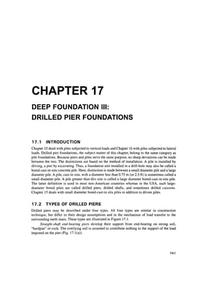
Figure 17.1 Types of drilled piers and underream shapes (Woodward et al., 1972)
Straight-shaft side wallfriction piers pass through overburden soils that are assumed to carry
none of the load, and penetrate far enough into an assigned bearing stratum to develop design load
capacity by side wall friction between the pier and bearing stratum (Fig. 17.1(b)).
Combination of straight shaft side wall friction and end bearing piers are of the same
construction as the two mentioned above, but with both side wall friction and end bearing assigned
a role in carrying the design load. When carried into rock, this pier may be referred to as a socketed
pier or a "drilled pier with rock socket" (Fig. 17.1(c)).
Belled or underreamed piers are piers with a bottom bell or underream (Fig.17.1(d)). A
greater percentage of the imposed load on the pier top is assumed to be carried by the base.
3. Deep Foundation III: Drilled Pier Foundations 743
17.3 ADVANTAGES AND DISADVANTAGES OF DRILLED PIER
FOUNDATIONS
Advantages
1. Pier of any length and size can be constructed at the site
2. Construction equipment is normally mobile and construction can proceed rapidly
3. Inspection of drilled holes is possible because of the larger diameter of the shafts
4. Very large loads can be carried by a single drilled pier foundation thus eliminating the
necessity of a pile cap
5. The drilled pier is applicable to a wide variety of soil conditions
6. Changes can be made in the design criteria during the progress of a job
7. Ground vibration that is normally associated with driven piles is absent in drilled pier
construction
8. Bearing capacity can be increased by underreaming the bottom (in non-caving materials)
Disadvantages
1. Installation of drilled piers needs a careful supervision and quality control of all the
materials used in the construction
2. The method is cumbersome. It needs sufficient storage space for all the materials used in
the construction
3. The advantage of increased bearing capacity due to compaction in granular soil that could
be obtained in driven piles is not there in drilled pier construction
4. Construction of drilled piers at places where there is a heavy current of ground water flow
due to artesian pressure is very difficult
17.4 METHODS OF CONSTRUCTION
Earlier Methods
The use of drilled piers for foundations started in the United States during the early part of the
twentieth century. The two most common procedures were the Chicago and Gow methods shown in
Fig. 17.2. In the Chicago method a circular pit was excavated to a convenient depth and a
cylindrical shell of vertical boards or staves was placed by making use of an inside compression
ring. Excavation then continued to the next board length and a second tier of staves was set and the
procedure continued.The tiers could be set at a constant diameter or stepped in about 50 mm. The
Gow method, which used a series of telescopic metal shells, is about the same as the current method
of using casing except for the telescoping sections reducing the diameter on successive tiers.
Modern Methods of Construction
Equipment
There has been a phenomenal growth in the manufacture and use of heavy duty drilling equipment
in the United States since the end of World War II. The greatest impetus to this development
occurred in two states, Texas and California (Woodward et al., 1972). Improvements in the
machines were made responding to the needs of contractors. Commercially produced drilling rigs
of sufficient size and capacity to drill pier holes come in a wide variety of mountings and driving
arrangements. Mountingsare usuallytruck crane, tractor or skid. Fig. 17.3 shows a tractor mounted
rig. Drilling machine ratings as presented in manufacturer's catalogs and technical data sheets are
4. 744 Chapter 17
Staves
Compression
ring
< V <
Telescoping
metal
Dig by
hand
(b) The Gow method
(a) The Chicago method
Figure 17.2 Early methods of caisson construction
usually expressed as maximum hole diameter, maximum depth, and maximum torque at some
particular rpm.
Many drilled pier shafts through soil or soft rock are drilled with the open-helix auger. The
tool may be equipped with a knife blade cutting edge for use in most homogeneous soil or with
hard-surfaced teeth for cutting stiff or hard soils, stony soils, or soft to moderately hard rock. These
augers are available in diameters up to 3 m or more. Fig. 17.4 shows commercially available
models.
Underreaming tools (or buckets) are available in a variety of designs. Figure 17.5 shows a
typical 30° underreamer with blade cutter for soils that can be cut readily. Most such underreaming
tools are limited in size to a diameter three times the diameter of the shaft.
When rock becomes too hard to be removed with auger-type tools, it is often necessary to
resort to the use of a core barrel. This tool is a simple cylindrical barrel, set with tungsten carbide
teeth at the bottom edge. For hard rock which cannot be cut readily with the core barrel set with
hard metal teeth, a calyx or shot barrel can be used to cut a core of rock.
General Construction Methods of Drilled Pier Foundations
The rotary drilling method is the most common method of pier construction in the United States.
The methods of drilled pier construction can be classified in three categories as
1. The dry method
2. The casing method
3. The slurry method
5. Deep Foundation III: Drilled Pier Foundations 745
Figure 17.3 Tractor mounted hydraulic drilling rig (Courtesy: Kelly Tractor Co,
USA)
Dry Method of Construction
The dry method is applicable to soil and rock that are above the water table and that will not cave or
slump when the hole is drilled to its full depth. The soil that meets this requirement is a
homogeneous, stiff clay. The first step in making the hole is to position the equipment at the desired
location and to select the appropriate drilling tools. Fig. 17.6(a) gives the initial location. The
drilling is next carried out to its fill depth with the spoil from the hole removed simultaneously.
After drilling is complete, the bottom of the hole is underreamed if required. Fig. 17.6(b) and
(c) show the next steps of concreting and placing the rebar cage. Fig 17.6(d) shows the hole
completely filled with concrete.
6. 746 Chapter 17
Figure 17.4 (a) Single-flight auger bit with cutting blade for soils, (b) single-flight
auger bit with hard-metal cutting teeth for hard soils, hardpan, and rock, and (c) cast
steel heavy-duty auger bit for hardpan and rock (Source: Woodward et al., 1972)
Figure 17.5 A 30° underreamer with blade cutters for soils that can be cut readily
(Source: Woodward et al., 1972)
7. Deep Foundation III: Drilled Pier Foundations 747
Casing Method of Construction
The casing method is applicable to sites where the soil conditions are such that caving or excessive
soil or rock deformation can occur when a hole is drilled. This can happen when the boring is made
in dry soils or rocks which are stable when they are cut but will slough soon afterwards. In such a
Competent,
non-caving soil
Surface casing,
if required
^^f^?^^. -
~ soil
>
&
V
/9K*7re>0«x!W!v/WJiK /9s< /n> /?v
^^—Drop ch"ute
3
(a) (b)
- Competent,
_ non-caving soil
/7!iWWJ«!'W>C'WW^/WX«<>
-
Competent,
non-caving soil
^^
»-^
•/'V
.';•
;••_;
3iKyi>iKxWI)^WXWX'iK
(c) (d)
Figure 17.6 Dry method of construction: (a) initiating drilling, (b) starting concrete
pour, (c) placing rebar cage, and (d) completed shaft (O'Neill and Reese, 1999)
8. 748 Chapter 17
case, the bore hole is drilled, and a steel pipe casing is quickly set to prevent sloughing. Casing is
also required if drilling is required in clean sand below the water table underlain by a layer of
impermeable stones into which the drilled shaft will penetrate. The casing is removed soon after the
concrete is deposited. In some cases, the casing may have to be left in place permanently. It may be
noted here that until the casing is inserted, a slurry is used to maintain the stability of the hole. After
the casing is seated, the slurry is bailed out and the shaft extended to the required depth.
Figures 17.7(a) to (h) give the sequence of operations. Withdrawl of the casing, if not done
carefully, may lead to voids or soil inclusions in the concrete, as illustrated in Fig. 17.8.
'Caving soil '.-;. •'.. V'"'•''"•'- ''•'•''." !'.',.':... ' - ; " : ' "
-_-_ Cohesive soil.
(a) (b)
_ _ Cohesive soil.
Cohesive soil"_~_~_~_~.
Cohesive soil.
(c) (d)
Figure 17.7 Casing method of construction: (a) initiating drilling, (b) drilling with
slurry; (c) introducing casing, (d) casing is sealed and slurry is being removed from
interior of casing (continued)
9. Deep Foundation III: Drilled Pier Foundations 749
Slurry Method of Construction
The slurry method of construction involves the use of a prepared slurry to keep the bore hole stable
for the entire depth of excavation. The soil conditions for which the slurry displacement method is
applicable could be any of the conditions described for the casing method. The slurry method is a
~ ~ ~ Competent soil ~ ~ _ ~ J
(e) (f)
Level of
fluid concrete
Drilling fluid
forced from
space between
casing and soil
/W^>8<^>B<N^B<N^i8<NX>B<^>B<NX>9<N
^
J
Competent soil j>
r Caving soil ;.-> ~ .->
Competent soil
/
/*
7$
::: $**
f!"*;*••
1 J
l;-'l
->i
W
^
-•'•^i
!
*«*
• .«
'•V^".:
•ft**"'1
»Wf%
'^••,
4*fc
v.^*l
.:-.--^
/WN^SKN^TOv^iKVWNXW
5
[::::::::::
;i:^:;'::..:
v^
»V
X
£*A
k!4>A
t >'; -J
(g) (h)
Figure 17.7 (continued) casing method of construction: (e) drilling below casing,
(f) underreaming, (g) removing casing, and (h) completed shaft (O'Neill and
Reese, 1999)
10. 750 Chapter 17
Casing Casing Casing
I being 4 being f being
yA. removed y^s. removed /^removed
z&z
T
conci
'.'*.; ',
o
O
U. .
/^
•'. o
•• o >
.-: U ••;
X>9< /X
Void due to
/S' arching
V,
^
Bearing
^•K
c
o
V U
/Ws /W
^ Soft soil
'*-SN squeezing in
Bearing
•*•;
V
.
'•*.-)
-
»
Concrete
•»••
•
•
"
'
*
(
'.**.'
/^r~*~^
X^
:
.
'
*
••>'
1
xw
Water flows up
— through concrete
causing segregation
/"- Waterfilledvoid
Bearing
stratum stratum stratum
oo much Too little Void in water bearingstratum
ete in casing concrete in casing prior to placingcasing
Figure 17.8 Potential problems leading to inadequate shaft concrete due to
removal of temporary casing without care (D'Appolonia, et al., 1 975)
viable option at any site where there is a caving soil, and it could be the only feasible option in a
permeable, water bearing soil if it is impossible to set a casing into a stratum of soil or rock with low
permeability. The various steps in the construction process are shown in Fig. 17.9. It is essential in
this method that a sufficient slurry head be available so that the inside pressure is greater than that
from the GWT or from the tendency of the soil to cave.
Bentonite is most commonly used with water to produce the slurry. Polymer slurry is also
employed. Some experimentation may be required to obtain an optimum percentage for a site, but
amounts in the range of 4 to 6 percent by weight of admixture are usually adequate.
The bentonite should be well mixed with water so that the mixture is not lumpy. The slurry
should be capable of forming a filter cake on the side of the bore hole. The bore hole is generally not
underreamed for a bell since this procedure leaves unconsolidated cuttings on the base and creates
a possibility of trapping slurry between the concrete base and the bell roof.
If reinforcing steel is to be used, the rebar cage is placed in the slurry as shown in Fig 17.9(b).
After the rebar cage has been placed, concrete is placed with a tremie either by gravity feed or by
pumping. If a gravity feed is used, the bottom end of the tremie pipe should be closed with a closure
plate until the base of the tremie reaches the bottom of the bore hole, in order to prevent
contamination of the concrete by the slurry. Filling of the tremie with concrete, followed by
subsequent slight lifting of the tremie, will then open the plate, and concreting proceeds. Care must
be taken that the bottom of the tremie is buried in concrete at least for a depth of 1.5 m (5 ft). The
sequence of operations is shown in Fig 17.9(a) to (d).
11. Deep Foundation Drilled Pier Foundations 751
: Cohesive soil
• Caving soil
(a) (b)
~ :Cohesive soil
Caving soil
. Caving soil
(c) (d)
Figure 17.9 Slurry method of construction (a) drilling to full depth with slurry;
(b) placing rebar cage; (c) placing concrete; (d) completed shaft (O'Neill and
Reese, 1999)
17.5 DESIGN CONSIDERATIONS
The precess of the design of a drilled pier generally involves the following:
1. The objectives of selecting drilled pier foundations for the project.
2. Analysis of loads coming on each pier foundation element.
3. A detailed soil investigation and determining the soil parameters for the design.
4. Preparation of plans and specifications which include the methods of design, tolerable
5.
settlement, methods of construction of piers,etc.
The method of execution of the project.
12. 752 Chapter 17
In general the design of a drilled pier may be studied under the following headings.
1. Allowable loads on the piers based on ultimate bearing capacity theories.
2. Allowable loads based on vertical movement of the piers.
3. Allowable loads based on lateral bearing capacity of the piers.
In addition to the above, the uplift capacity of piers with or without underreams has to be
evaluated.
The following types of strata are considered.
1. Piers embedded in homogeneous soils, sand or clay.
2. Piers in a layered system of soil.
3. Piers socketed in rocks.
It is better that the designer select shaft diameters that are multiples of 150 mm (6 in) since
these are the commonly availabledrilling tool diameters.
17.6 LOAD TRANSFER MECHANISM
Figure 17.10(a) shows a single drilled pier of diameter d, and length L constructed in a
homogeneous mass of soil of known physical properties. If this pier is loaded to failure under an
ultimate load Qu, a part of this load is transmitted to the soil along the length of the pier and the
balance is transmitted to the pier base. The load transmitted to the soil along the pier is called the
ultimatefriction load or skin load, Qfand that transmitted to the base is the ultimate base or point
load Qb. The total ultimate load, Qu, is expressed as (neglecting the weight of the pier)
where qb = net ultimatebearing pressure
Ab = base area
fsi - unit skin resistance (ultimate) of layer i
P. = perimeter of pier in layer i
Az(. = thickness of layer i
N = number of layers
If the pier is instrumented,the load distribution along the pier can be determined at different
stages of loading. Typical load distribution curves plotted along a pier are shown in Fig 17.10(b)
(O'Neill and Reese, 1999). These load distribution curves are similar to the one shown in
Fig. 15.5(b). Since the load transfer mechanism for a pier is the same as that for a pile, no further
discussion on this is necessary here. However, it is necessary to study in this context the effect of
settlement on the mobilization of side shear and base resistance of a pier. As may be seen from
Fig. 17.11, the maximum values of base and side resistance are not mobilized at the same value of
displacement. In some soils, and especially in some brittle rocks, the side shear may develop fully
at a small value of displacement and then decrease with further displacement while the base
resistance is still being mobilized (O'Neill and Reese, 1999). If the value of the side resistance at
point A is added to the value of the base resistance at point B, the total resistance shown at level D
is overpredicted. On the other hand, if the designer wants to take advantage primarily of the base
resistance, the side resistance at point C should be added to the base resistance at point B to evaluate
Q . Otherwise, the designer may wish to design for the side resistance at point A and disregard the
base resistance entirely.
13. Deep Foundation III: Drilled Pier Foundations 753
ia
,
Qt
d
1 1
Qb
Applied load, kips
500 1000 1500 2000
(a) (b)
Figure 17.10 Typical set of load distribution curves (O'Neill and Reese, 1999)
Actual
ultimate
resistance
Ultimate side
resistance
Ultimate base
resistance
Settlement
Figure 17.11 Condition in which (Qb + Qf) is not equal to actual ultimate resistance
14. 754 Chapter 17
17.7 VERTICAL BEARING CAPACITY OF DRILLED PIERS
For the purpose of estimating the ultimate bearing capacity, the subsoil is divided into layers
(Fig. 17.12) based on judgment and experience (O'Neill and Reese, 1999). Each layer is assigned
one of four classifications.
1. Cohesive soil [clays and plastic silts with undrained shear strength cu < 250 kN/m2
(2.5 t/ft2
)] .
2. Granular soil [cohesionless geomaterial, such as sand, gravel or nonplastic silt with
uncorrected SPT(N) values of 50 blows per 0.3/m or less].
3. Intermediate geometerial [cohesive geometerial with undrained shear strength cu between
250 and 2500 kN/m2
(2.5 and 25 tsf), or cohesionless geomaterial with SPT(N) values > 50
blows per 0.3 mj.
4. Rock [highly cemented geomaterial with unconfmed compressive strength greater than
5000 kN/m2
(50 tsf)J.
The unit side resistance /, (=/max) is computed in each layer through which the drilled shaft
passes, and the unit base resistance qh (=<7max) is computed for the layer on or in which the base of
the drilled shaft is founded.
The soil along the whole lengthof the shaft is divided into four layers as shown in Fig. 17.12.
Effective Length for Computing Side Resistance in Cohesive Soil
O'Neill and Reese (1999) suggest that the following effective length of pier is to be considered for
computing side resistance in cohesive soil.
Qu
/^ /V3 /%x$
Layer 1
t
Layer 2
i ,
Layer 3
!,
Layer 4
d
//T^. /^ //F^ ,
''Qfl 7
1
"2/2 i
l(
Qfl *
2
3
'2/4
a
Figure 17.12 Idealized geomaterial layering for computation of compression load
and resistance (O'Neill and Reese, 1999)
15. Deep Foundation Drilled Pier Foundations 755
Straight shaft: One diameter from the bottom and 1.5 m (5 feet) from the top are to be excluded
from the embedded length of pile for computing side resistance as shown in Fig. 17.13(a).
Belled shaft: The height of the bell plus the diameter of the shaft from the bottom and 1.5 m (5 ft)
from the top are to be excluded as shown in Fig 17.13(b).
17.8 THE GENERAL BEARING CAPACITY EQUATION FOR THE
BASE RESISTANCE qb (= </max)
The equation for the ultimatebase resistance may be expressed as
,<w • — vd v d N
/
1
* J
V W
V * * V
9 Y 7 r (17.2)
where /Vc, N and N = bearing capacity of factors for long footings
5C, s and s = shape factors
dc, d and d = depth factors
q'0 = effective vertical pressure at the base level of the drilled pier
7 = effective unit weightof the soil below the bottom of the drilled shaft to a
depth = 1.5 d where d = width or diameter of pier at base level
c = average cohesive strength of soil just below the base.
For deep foundations the last term in Eq. (17.2) becomes insignificant and may be ignored.
Now Eq. (17.2) may be written as
(17.3)
V c + s d (N —}q'
c q q^ q >^o
/^
L
/ww
d
i
!5ft= 1.5m
L
.^XxS*
• 5' =
E
•s:
i1
^
"iT
Effective length £ ^
L' = L-(d+ 1.5)m <g II
UJ
d
h
d
*j
^?^
1.5 m
d
/
(a)
db
(b)
Figure 17.13 Exclusion zones for estimating side resistance for drilled shafts in
cohesive soils
16. 756 Chapter 17
17.9 BEARING CAPACITY EQUATIONS FOR THE BASE IN
COHESIVE SOIL
When the Undrained Shear Strength, cu < 250 kN/m2
(2.5 t/ft2
)
For 0 = 0, Nq = 1 and (Nq - 1) = 0, here Eq. (17.3) can be written as (Vesic, 1972)
4b =N
lc
u (17.4)
in which
N*=-(nIr+l) (17.5)
Ir - rigidity index of the soil
Eq. (17.4) is applicable for cu < 96 kPa and L>3d (base width)
For 0= 0, /. may be expressed as (O'Neill and Reese, 1999)
/r =
3^" (I7
-6
)
where Es =Young's modulus of the soil in undrained loading. Refer to Section 13.8 for the methods
of evaluating the value of Es.
Table 17.1 gives the values of Ir and N *as a function of c .
If the depth of base (L) < 3d (base)
2 L
^(=
<?max) = - 1 + — N*cu (17J)
When cu > 96 kPa (2000 lb/ft2
), the equation for qb may be written as
9b=*u (17.8)
for depth of base (= L) > 3d (base width).
17.10 BEARING CAPACITY EQUATION FOR THE BASE IN
GRANULAR SOIL
Values NC and N in Eq. (17.3) are for strip footings on the surface of rigid soils and are plotted as
a function of 0 in Fig. 17.14. Vesic (1977) explained that during bearing failure, a plastic failure
zone develops beneath a circular loaded area that is accompanied by elastic deformation in the
surrounding elastic soil mass. The confinement of the elastic soil surrounding the plastic soil has an
effect on qb (= <?max). The values of Nc and N are therefore dependent not only on 0, but also on Ir.
They must be corrected for soil rigidity as given below.
Table 17.1 Values of lr = Es/3cu and A/c*
', "?
24 kPa (500 lb/ft
2
) 50 6.5
48 kPa (1000 lb/ft
2
) 150 8.0
> 96 kPa (2000 lb/ft2
) 250-300 9.0
17. DeepFoundation Drilled Pier Foundations 757
Nc (corrected) = NcCc
Nq (corrected) = NqCq
where Cc and C are the correction factors. As per Chen and Kulhawy (1994)
Eq (17.3) may now be expressed as
(17.9)
(17.10)
1-C
r - r q
c q
Nctan0 (1
C? =exp {[-3.8tan 0]+ [(3.07sin 0)log102/rr]/(l + sin 0)} (17.11b)
where 0 is an effective angle of internal friction. Irr is the reduced rigidity index expressed as
[Eq. (15.28)]
/ =
and /. =
by ignoring cohesion, where,
(17.12)
(17.13)
CQ
10 20 30 40
Friction angle, 0 (degrees)
50
Figure 17.14 Bearing capacity factors (Chen and Kulhawy, 1994)
18. 758 Chapter 17
Ed = drained Young's modulus of the soil
id = drained Poisson's ratio
A = volumetric strain within the plastic zone during the loading process
The expressions for nd and A may be written as (Chen and Kulhawy, 1994)
/)rel (17.14)
0.005(1 -0rel)g'0
- -- (17.15)
where (j)rel =~^-~- for 25° < <p° < 45° (17.16)
45 -25°
= relative friction angle factor, pa = atmospheric pressure =101 kPa.
Chen and Kulhawy (1994) suggest that, for granular soils, the following values may be
considered.
loose soil, Ed - 100 to 200pfl (17.17)
medium dense soil, Ed = 200 to 500pa
dense soil, Ed = 500 to 1000pa
The correction factors Cc and C indicated in Eq. (17.9) need be applied only if In is less than
the critical rigidity index (/r)crit expressed as follows
(7
r)cr=|ex
P 2
-85cot 45
°-f (17.18)
The values of critical rigidity index may be obtained from Table 12.4 for piers circular or
square in section.
If lrr > (/r)crit , the factors Cc and C may be taken as equal to unity.
The shape and depth factors in Eq. (17.3) can be evaluated by making use of the relationships
given in Table17.2.
Table 17.2 Shape and depth factors (Eq.17.3)(Chen and Kulhawy, 1994)
Factors Value
N
s 1+ —
N
v-
1 + tan <f)
sin0)2
tan'1
—
180 d
19. Deep Foundation III: Drilled Pier Foundations 759
Base in Cohesionless Soil
The theoretical approach as outlinedabove is quitecomplicated and difficult to apply in practice for
drilled piers in granular soils. Direct and simple empirical correlations have been suggested by
O'Neill and Reese (1999) between SPT TV value and the base bearing capacity as given below for
cohesionless soils.
<2900kN/m2
(17.19a)
<30tsf (17.19b)
where N = SPT value < 50 blows / 0.3 m.
Base in Cohesionless IGM
Cohesionless IGM's are characterized by SPT blow counts if more than 50 per 0.3 m. In such cases,
the expression for qb is
0.8
<^(=4max) = 0-60 Af60^7 q'0 (17.20)
tfo
where W60 = average SPT corrected for 60 percent standard energy within a depth of 2d
(base) below the base. The value of A^ is limited to 100. No correction for
overburden pressure
pa = atmospheric pressure in the units used for q'o (=101 kPa in the SI System)
q'0 = vertical effective stress at the elevation of the base of the drilled shaft.
17.11 BEARING CAPACITY EQUATIONS FOR THE BASE IN
COHESIVE IGM OR ROCK (O'NEILL AND REESE, 1999)
Massive rock and cohesive intermediate materials possess common properties. They possess low
drainage qualities under normal loadings but drain more rapidly under large loads than cohesive
soils. It is for these reasons undrained shear strengths are used for rocks and IGMs.
If the base of the pier lies in cohesive IGM or rock (RQD =100 percent) and the depth of socket,
Dv, in the IGM or rock is equal to or greater than l.5d, the bearing capacity may be expressed as
(17.21)
where qu = unconfmed compressive strength of IGM or rock below the base
For RQD between 70 and 100percent,
For jointed rock or cohesive IGM
?*(= ^max) = [*°-5
+(ms°-5
+s)°-5
]qu (17.23)
where qu is measured on intact cores from within 2d (base) below the base of the drilled pier. In all
the above cases qb and qu are expressed in the same units and s and m indicate the properties of the
rock or IGM mass that can be estimated from Tables 17.3 and 17.4.
20. 760 Chapter 17
Table 17.3 Descriptions of rock types
Rock type Description
A Carbonate rocks with well-developed crystal cleavage (eg., dolostone,limestone,
marble)
B Lithified argillaeous rocks (mudstone, siltstone, shale, slate)
C Arenaceousrocks (sandstone, quartzite)
D Fine-grained igneous rocks (andesite, dolerite, diabase,rhyolite)
E Coarse-grained igneous and metamorphic rocks (amphibole, gabbro, gneiss,granite,
norite, quartz-diorite)
Table 17.4 Values of s and m (dimensionless) based on rock classification (Carter
and Kulhawy, 1988)
Quality of
rock mass
Excellent
Very good
Good
Fair
Poor
Very poor
Joint description
and spacing
Intact (closed);
spacing > 3 m (10 ft)
Interlocking;
spacing of 1 to 3 m (3 to 10 ft)
Slightly weathered;
spacing of 1 to 3 m (3 to 10 ft)
Moderatelyweathered;
spacing of 0.3 to 1m (1 to 3 ft)
Weathered with gouge (soft material);
spacing of 30 to 300 mm (1 in. to 1 ft)
Heavily weathered;
spacing of less than 50 mm (2in.)
s
1
0.1
4x1 Q~2
10~4
10~5
0
Value of m as function of rock type
(A-E) from
A B C D E
7 10 15 17 25
3.5 5 7.5 8.5 12.5
0.7 1 1.5 1.7 2.5
0.14 0.2 0.3 0.34 0.5
0.04 0.05 0.08 0.09 0.13
0.007 0.01 0.015 0.017 0.025
17.12 THE ULTIMATE SKIN RESISTANCE OF COHESIVE AND
INTERMEDIATE MATERIALS
Cohesive Soil
The process of drilling a borehole for a pier in cohesive soil disturbs the natural condition of the soil
all along the side to a certain extent. There is a reduction in the soil strength not only due to boring
but also due to stress relief and the time spent between boring and concreting. It is very difficult to
quantify the extent of the reduction in strength analytically.In order to take care of the disturbance,
the unit frictional resistance on the surface of the pier may be expressed as
fs=acu (17.24)
where a — adhesion factor
cu - undrained shear strength
Relationships have been developed between cu and a by many investigators based on field
load tests. Fig 17.15 gives one such relationship in the form of a curve developed by Chen and
Kulhawy (1994). The curve has been developed on the following assumptions (Fig. 17.15).
21. Deep Foundation III: Drilled Pier Foundations 761
l.U
0.8
0.6
0.4
0.2
0.0
0
-
• ,
4
1 1 1 1
4
4.^.
»4+
4
t ^^
4
i i
4
^i ^^^
4
i i
1 <
4
r
i i
Design at
* Intermei
geomater
^
»
i i i i
liate
lal"
^ 4
i i i i
0 1.0 2.0 3.0 4.0 5.
Figure 17.15 Correlation between a and cjpa
f = 0 up to 1.5 m ( = 5 ft) from the ground level.
fs = 0 up to a height equal to (h + d) as per Fig 17.13
O'Neill and Reese (1999) recommend the chart's trend line given in Fig. 17.15 for designing
drilled piers. The suggested relationships are:
a =0.55 for cu I pa < 1.5
and a =0.55 -0.1
Pa
for 1.5<c I pa <2.5
(17.25a)
(17.25b)
Cohesive Intermediate Geomaterials
Cohesive IGM's are very hard clay-like materials which can also be considered as very soft rock
(O'Neill and Reese, 1999). IGM's are ductile and failure may be sudden at peak load. The value of
fa (please note that the term fa is used instead of fs for ultimate unit resistance at infinite
displacement) depends upon the side condition of the bore hole, that is, whether it is rough or
smooth. For design purposes the side is assumed as smooth. The expression for/ may be written as
fa=a<lu (17.26)
where, q = unconfmed compressive strength
/ = the value of ultimate unit side resistance which occurs at infinite displacement.
Figure 17.16 gives a chart for evaluating a. The chart is prepared for an effective angle of
friction between the concrete and the IGM (assumingthat the intersurface is drained) and St denotes
the settlement of piers at the top of the socket. Further, the chart involves the use of on lpa where on
is the normal effective pressure against the side of the borehole by the drilled pier and pa is the
atmospheric pressure (101 kPa).
22. 762 Chapter 17
0.0
^, = 30°
115 <£,„/<?„< 500
5, = 25 mm
Figure 17.16 Factor a for cohesive IGM's (O'Neill and Reese, 1999)
Table 17.5 Estimation of EmIEj based on ROD (Modified after Carter and Kulhawy,
1988)
ROD (percent) Closed joints Open joints
100
70
50
20
1.00
0.70
0.15
0.05
0.60
0.10
0.10
0.05
Note: Values intermediate between tabulated values may be obtained by linear interpolation.
Table 17.6 flfa based on EJE, (O'Neill et al., 1996)
da a in i
1.0
0.5
0.3
0.1
0.05
1.0
0.8
0.7
0.55
0.45
23. Deep Foundation III: Drilled Pier Foundations 763
1.0
0.8
M
-•- Depth =0 m
-O- Depth = 4m
-•- Depth = 8 m
-D-Depth = 12m
125 175
Slump (mm)
200 225
Figure 17.17 Factor M versus concrete slump (O'Neill et al., 1996)
O'Neill and Reese (1999) give the following equation for computing an
on = Myczc (17.27)
where yc = the unit weight of the fluid concrete used for the construction
zc = the depth of the point at which o~M is required
M = an empirical factor which depends on the fluidity of the concrete as indexed by
the concrete slump
Figure 17.17 gives the values of M for various slumps.
The mass modulusof elasticity of the IGM (Em) shouldbe determined before proceeding, in order
to verify that the IGM is within the limits of Fig 17.16. This requires the average Young's modulusof
intact IGM core (£.) which can be determined in the laboratory. Table 17.5gives the ratios ofEm/E{ for
various values of RQD. ValuesQiEJEi less than unity indicate that soft seams and/orjoints exist in the
IGM. These discontinuitiesreduce the valueoffa. The reduced value offa may be expressed as
f = f R
J aa •'a a
where the ratio Ra =faa/fa can be determined from Table 17.6.
If the socket is classified as smooth, it is sufficiently accurate to set/^ =/max =faa
(17.28)
17.13 ULTIMATE SKIN RESISTANCE IN COHESIONLESS SOIL
AND GRAVELLY SANDS (O'NEILL AND REESE, 1999}
In Sands
A general expression for total skin resistance in cohesionless soil may be written as [Eq.(17.1)]
(17.29)
24. 764 Chapter 17
or Qfi= />/?.<;.Az. (1730)
where fsi = ft.cf 'Ol (17.31)
A = Ksi tan 8.
<5. = angle of skin friction of the / th layer
The following equations are provided by O'Neill and Reese (1999) for computing /?..
For SPT N6Q (uncorrected) > 15 blows / 0.3 m
$ = 1.5-0.245[z.]0
-5
(17.32)
For SPT N6Q (uncorrected) < 15 blows / 0.3 m
(17.33)
In Gravelly Sands or Gravels
For SPT N6Q > 15 blows / 0.3 m
fl. =2.0-0.15[z.]°-75
(17.34)
In gravelly sands or gravels, use the method for sands if yV60 < 15 blows / 0.3 m.
The definitions of various symbols used above are
/3;. = dimensionless correlation factor applicable to layer i. Limited to 1.2 in sands
and 1.8 in gravelly sands and gravel. Minimum value is 0.25 in both types of
soil; fsi is limited 200 kN/m2
(2.1 tsf)
q'oi = vertical effective stress at the middle of each layer
/V60 = design value for SPT blow count, uncorrected for depth, saturation or fines
corresponding to layer /
Z; - vertical distance from the ground surface, in meters, to the middle of layer i.
The layer thickness Az;. is limited to 9 m.
17.14 ULTIMATE SIDE AND TOTAL RESISTANCE IN ROCK
(O'NEILL AND REESE, 1999)
Ultimate Skin Resistance (for Smooth Socket)
Rock is defined as a cohesive geomaterial with qu >5 MPa (725 psi). The following equations may
be used for computing fs ( =/max) when the pier is socketed in rock. Two methods are proposed.
Method 1
0.5 0.5
fs(=fmJ = ^Pa~ *0.65paA- (17.35)
* a ' a
where, pa = atmospheric pressure (= 101 kPa)
qu = unconfmed compressive strength of rock mass
fc = 28 day compressive cylinder strength of concrete used in the drilled pier
25. Deep Foundation III: Drilled Pier Foundations 765
Method 2
0.5
fs(=fmJ = ^Pa^- (17.36)
Pa
Carter and Kulhawy (1988) suggested equation (17.36) based on the analysis of 25 drilled
shaft socket tests in a very wide variety of soft rock formations, including sandstone, limestone,
mudstone, shale and chalk.
Ultimate Total Resistance Qu
If the base of the drilled pier rests on sound rock, the side resistance can be ignored. In cases where
significant penetration of the socket can be made, it is a matter of engineering judgment to decide
whether Q,should be added directly to Qb to obtain the ultimatevalue Qu,When the rock is brittle
in shear, much side resistance will be lost as the settlement increases to the value required to
develop the full value of qb (=qmax)- If the rock is ductile in shear, there is no question that the two
values can be added direcily (O'Neill and Reese, 1999).
17.15 ESTIMATION OF SETTLEMENTS OF DRILLED PIERS AT
WORKING LOADS
O'Neill and Reese (1999) suggest the following methods for computing axial settlements for
isolated drilled piers:
1. Simple formulas
2. Normalized load-transfer methods
The total settlement St at the pier head at working loads may be expressed as (Vesic, 1977)
s
t=Se+Sbb+Sbs (17.37)
where, Se = elastic compression
Sbb = settlement of the base due to the load transferred to the base
Sbs = settlement of the base due to the load transferred into the soil along the sides.
The equations for the settlements are
AbE
r _ /~<
bb=
where L = length of the drilled pier
Ab = base cross-sectional area
E = Young's modulus of the drilled pier
Qa = load applied to the head
<2> = mobilized side resistance when Qa is applied
26. 766 Chapter 17
Table 17.7 Values of C for various soils (Vesic, 1977)
Soil Cp
Sand (dense)
Sand (loose)
Clay (stiff)
Clay (soft)
Silt (dense)
Silt (loose)
0.09
0.18
0.03
0.06
0.09
0.12
Qbm = mobilized base resistance
d = pier width or diameter
C = soil factor obtained from Table 17.7
Normalized Load-Transfer Methods
Reese and O'Neill (1988) analyzed a series of compression loading test data obtained from full-
sized drilled piers in soil. They developed normalized relations for piers in cohesive and
cohesionless soils. Figures 17.18 and 17.19 can be used to predict settlements of piers in cohesive
soils and Figs. 17.20 and 17.21 in cohesionless soils includingsoil mixed with gravel.
The boundary limits indicated for gravel in Fig. 17.20 have been found to be approximately
appropriate for cemented fine-grained desert IGM's (Walsh et al., 1995). The range of validity of
the normalized curves are as follows:
).0 0.2 0.4 0.6 0.8 1.0 1.2 1.4 1.6 1.8 2.0
Settlement ~
Settlement ratio SR =
Diameter of shaft
Figure 17.18 Normalized side load transfer for drilled shaft in cohesive soil (O'Neill
and Reese, 1999)
27. Deep Foundation III: Drilled Pier Foundations 767
0 1 3 4 5 6 7
Settlement of base
Diameter of base
10
Figure 17.19 Normalized base load transfer for drilled shaft in cohesive soil
(O'Neill and Reese, 1999)
Range of results for
deflection-softening response
Range of results for
deflection-hardening response
Trend line
i.O « L
0.0 0.2 0.4 0.6 0.8 1.0 1.2 1.4 1.6 1.8 2.0
S = Settlement ~
R
Diameter of shaft
Figure 17.20 Normalized side load transfer for drilled shaft in cohesionless soil
(O'Neill and Reese, 1999)
28. 768 Chapter 17
2.Q
1.8
1.6
1.4
1.2
1.0
E 0.8
D
0.6
0.4
0.2
0.0
Range of results
1 2 3 4 5 6 7 8 9 10 11 12
c Settlement of base _,
O/j = %
Diameter of base
Figure 17.21 Normalized base load transfer for drilled shaft in cohesionless soil
(O'Neill and Reese, 1999)
Figures 17.18 and 17.19
Normalizing factor = shaft diameter d
Range of d = 0.46 m to 1.53 m
Figures 17.20 and 17.21
Normalizing factor = base diameter
Range of d = 0.46m to 1.53m
The following notations are used in the figures:
SD = Settlement ratio = S Id
A a
Sa = Allowable settlement
Nfm = Normalized side load transfer ratio = QrJQr
Nbm = Normalize base load transfer ratio = QbJQb
Example 17.1
A multistory building is to be constructed in a stiff to very stiff clay. The soil is homogeneous to a
great depth. The average value of undrained shear strength cu is 150 kN/m2
. It is proposed to use a
drilled pier of length 25 m and diameter 1.5 m. Determine (a) the ultimate load capacity of the pier,
and (b) the allowable load on the pier with Fs = 2.5. (Fig. Ex. 17.1)
Solution
Base load
When cu > 96 kPa (2000 Ib/ft2
), use Eq. (17.8) for computing qb. In this case cu > 96 kPa.
a. = 9c = 9 x 150 = 1350 kN/m2
29. Deep Foundation III: Drilled Pier Foundations 769
Q
, = 25m
c= 150kN/m2
Clay
d=1.5m
Figure Ex. 17.1
3 14 x 152
Base load Qb =Abqb= x 1350 =1.766 x 1350 = 2384 kN
Frictional load
The unit ultimate frictional resistancefs is determined using Eq. (17.24)
fs=ac
u
From Fig.(17.15) cc= 0.55for cjpa = 150/101 = 1.5
where pa is the atmospheric pressure =101 kPa
Therefore fs = 0.55 x 150 = 82.5 kN/m2
The effective length of the shaft for computing the frictional load (Fig.17.13 a) is
L' = [L-(d+ 1.5)] m = 25-(1.5+ 1.5) = 22m
The effective surface area As = ndL' = 3.14 x 1.5 x 22 = 103.62 m2
Therefore Qf=fs As = 82.5 x 103.62 = 8,549 kN
The total ultimate load is
Qu = Qf+ Qb = 8,549 + 2,384 = 10,933 kN
The allowable load may be determined by applying an overall factor of safety to Qu.
Normally FS = 2.5 is sufficient.
10933
= 4,373 kN
30. 770 Chapter 17
Example 17.2
For the problem given in Ex. 17.1, determine the allowable load for a settlement of 10 mm (= S ).
All the other data remain the same.
Solution
Allowable skin load
S 10
Settlement ratio SR =-*- = — x 100= 0.67%
(2 l.D X 1U
Qf
From Fig. 17.18 for SR = 0.67%, Nfm =-^ = 0.95 by using the trend line.
(2^ = 0.95 Qf= 0.95 x 8,549 = 8,122 kN.
Allowable base load for Sa = 10 mm
From Fig. 17.19 for SK = 0.67 %, N, = ^ = 0.4
w
A OiH f
Qbm = 0.4 Qb = 0.4 x 2,384 = 954 kN.
Now the allowable load Qas based on settlement consideration is
Qas= Qjm+Qbm= 8^122 -f 954 = 9,076 kN
Qas based on settlement consideration is very much higher than Qa (Ex. 17.1) and as such Qa
governs the criteria for design.
Example 17.3
Figure Ex. 17.3 depicts a drilled pier with a belled bottom. The details of the pile and the soil
properties are given in the figure. Estimate (a) the ultimate load, and (b) the allowable load with
Solution
Based load
Use Eq. (17.8) for computing qb
q = 9c =9x 200 =1,800 kN/m2
Ttd^ 1 14 x 32
Base load Qb=—^xqb=-- x1,800 = 12,717kN
Frictional load
The effective length of shaft L' = 25 - (2.75 + 1.5) = 20.75 m
From Eq. (17.24) fs=acu
For f«_ = 122. = i o , a = 0.55 from Fig. 17.15
Pa 101
Hence/y = 0.55 x 100 = 55 kN/m2
31. Deep Foundation III: Drilled Pier Foundations 771
1.25 m
G
=
/&$^
1.5
Z
25m
1
1 ,
l.i
2.75 m —
m
m
t-
^ ^
Clay
cu = 100 kN
d= 1.5m
Clay
w c.. = 200 kl
= 3 m
Figure Ex. 17.3
Qf = PL'fs = 3.14 x 1.5 x 20.75 x 55 = 5,375 kN
Qu = Qb + Qf= 12,717 + 5,375 = 18,092 kN
= kN
2.5
Example 17.4
For the problem given in Ex. 17.3, determine the allowable load Qas for a settlement Sa = 10 mm.
Solution
Skin load Q, (mobilized)
Settlement ratio SR = — x 100 = 0.67%
1.5 xlO3
From Fig. 17.18 for Sp = 0.67, N, = 0.95 from the trend line.
° A jtn
Therefore Q^ = 0.95 x 5,375 = 5,106 kN
Base load Qbm (mobilized)
SR= 10
, x 100 =0.33%
R
3xl03
From Fig. 17.19 for SR = 0.33%, Nbm = 0.3 from the trend line.
32. 772 Chapter 17
Hence Qbm = 0.3 x 12,717 = 3815 kN
Qas = Qfrn + Qbm = 5,106 + 3,815 = 8,921 kN
The factor of safety with respect to Q is (from Ex. 17.3)
F =
8,921
This is low as compared to the normally accepted value of Fs = 2.5. Hence Qa rules the
design.
Example 17.5
Figure Ex. 17.5 shows a straight shaft drilled pier constructed in homogeneous loose to medium
dense sand. The pile and soil properties are:
L = 25m, d= 1.5m, c = 0,0 =36° and y = 17.5 kN/m3
Estimate (a) the ultimate load capacity, and (b) the allowable load with Fg = 2.5. The average
SPT value Ncor = 30 for 0 = 36°.
Use (i) Vesic's method, and (ii) the O'Neill and Reese method.
Solution
(i) Vesic's method
FromEq. (17.10) fore = 0
<?;= 25x17.5 = 437.5 kN/m2
df —25° 36 — 25
From Eq.(17.16) <j)rd = *y _^ =-^- = 0.55
FromEq. (17.15) A - 0-005(1- 0-55) x 437.5 ^
101
FromEq. (17.14) jud =0.1 + 0.3^ =0.1+0.3x0.55 = 0.265
From Eq. (17.17) Ed =200pa = 200 x 101= 20,200 kN/m2
_ TT M-7 1 Q N , E
d 20,200
FromEq. (17.13) / = -2- = -:- = 25
r
' 2(1 + 0.265) x 437.5tan 36°
FromEq. (17.12) / = = _ _ = 20
"" 1 + A7, 1 + 0.01x25
FromEq. (17.lib)
C =exp [-3.8tan36°]+ ; ~ ° 1 U
= exp-(0.9399) = 0.391
3.07sin 36° Iog10 2x20
From Fig. 17.14, Nq = 30 for 0 = 36°
33. Deep Foundation III: Drilled Pier Foundations 773
Lj — i
'
15m
Sand
0 = 36°
c = 0
y = 17.5 kN/m3
A^ =30
d=1.5m
Figure Ex. 17.5
From Table (17.2) sq = 1+ tan 36° = 1.73
d =l + 2tan36°(l-sin36°)2
q
180
— =1.373
1.5
Substituting in Eq. (a)
qb =(30-1) x 437.5 x 1.73x 1.373 x 0.391 = 1 1,783 kN/m2
> 1 1,000 kN/m2
As per Tomlinson (1986) the computed qb should be less than 1 1,000 kN/m2
.
314
Hence Qb = -1
—x (1.5)2
x 1 1,000 = 19,429 kN
Skin load Qf
From Eqs (17.31) and (17.32)
fs=fa'0. 0= 1-5 -0.245z°-5
, where z = - = — = 12.5m
Substituting
0 =1.5 - 0.245 x (12.5)°-5
= 0.63
Hence fs = 0.63x437.5 = 275.62 kN/m2
Per Tomlinson (1986)fs should be limited to 1 10 kN/m2
. Hencefs = 1 10 kN/m2
Therefore Qf =ndLfs = 3.14 x 1.5 x 25 x 1 10 = 12,953 kN
34. 774 Chapter 17
Ultimate load Qu = 19,429+12,953 = 32,382 kN
G.=^= 12,953 kN
O'Neill and Reese method
This method relates qb to the SPT N value as per Eq. (17.19a)
qb =51.5N kN/m2
= 57.5 x 30 = 1,725 kN/m2
Qb =Abqb =1.766 x 1,725- 3,046 kN
The method for computingQ, remains the same as above.
Now Qu = 3,406 + 12,953 = 15,999
15999
^ w^v
a
2.5
Example 17.6
Compute Qu and Qa for the pier given in Ex. 17.5 by the following methods.
1. Use the SPT value [Eq. (1 5.48)j for bored piles
2. Use the Tomlinson method of estimating Qb and Table 15.2 for estimating Q,. Compare the
results of the various methods.
Solution
Use of the SPT value[Meyerhof Eq. (15.48)]
qb = U3Ncor = 133x 30 = 3,990 kN/m2
Qb =3
'14X(L5)2
x 3,990 = 7,047 kN
fs =0.67Wcor = 0.67 x 30 = 20 kN/m2
Qf =3.14x1.5x25x20 = 2,355 kN
Qu = 7,047 + 2,355 = 9,402 kN
_ 9,402
a
~ 2.5 ~ '
Tomlinson Method for Qb
For a driven pile
L 25
From Fig. 15.9 No = 65 for 0 = 36° and —= — * 17
a 1.5
Hence qb = q'oNq = 437.5 x 65 = 28,438 kN/m2
35. Deep Foundation III: Drilled Pier Foundations 775
For bored pile
qb=-qb (driven pile) = -x 28,438 = 9,479 kN/m2
Qb = Abqb = 1.766 x 9,479 = 16,740 kN
Qf from Table 15.2
For </» = 36°, 8 = 0.75 x 36 = 27, and Ks= 1.5 (formedium dense sand).
— 437 5
fs = q'o Ks tanS= -- x1.5 tan27° =167 kN/m2
As per Tomlinson (1986)/, is limited to 1 10 kN/m2
. Use/5 = 1 10 kN/m2
.
Therefore Qf = 3.14x 1.5 x 25 x 1 10 = 12,953 kN
Qu = Qb +Qf = 16,740 + 12,953 = 29,693 kN
=1
2.5
Comparison of estimated results (F = 2.5)
Example No
17.5
17.5
17.6
17.6
Name of method
Vesic
O'Neill and Reese, for Qb
and Vesic for Q,
MeyerhofEq. (15.49)
Tomlinson for Qb
(Fig. 15.9) Table 15.2for Qf
Qb (kN)
19,429
3,046
7,047
16,740
Q,(kN)
12,953
12,953
2,355
12,953
Qu (kN)
32,382
15,999
9,402
29,693
Qa (kN)
12.953
6,400
3,760
11,877
Which method to use
The variation in the values of Qb and Q, are very large between the methods. Since the soils
encountered in the field are generally heterogeneous in character no theory holds well for all the
soil conditions. Designers have to be practical and pragmatic in the selection of any one or
combination of the theoretical approaches discussed earlier.
Example 17.7
For the problem given in Example 17.5determine the allowable load for a settlement of 10mm. All
the other data remain the same. Use (a) the values of Q, and Qb obtained by Vesic's method, and
(b) Qb from the O'Neill and Reese method.
Solution
(a) Vesic's values g.and Qb
Settlement ratio for S = 10 mm is
d 1.5 xlO3
From Fig. 17.20 for SR = 0.67%N^ = 0.96 (approx.) using the trend line.
36. 776 Chapter 17
2^= 0.96x0,.= 0.96x12,953 =12,435 kN
From Fig. 17.21 for SR = 0.67%
Nbm =0.20, or Qbm =0.20x19,429 = 3,886 kN
Qas = 12,435 + 3,886 = 16,321 kN
Shear failure theory give Qa - 12,953 kN which is much lower than Qas. As such Qa
determines the criteria for design.
(b) O'Neill and Reese Qb = 3,046 kN
As above, Qbm = 0.20 x 3,046 = 609 kN
Using Qr in (a) above,
Qas = 609 + 12,435 = 13,044 kN
The value of Qas is closer to Qa (Vesic) but much higher than Qa calculated by all the other
methods.
Example 17.8
Figure Ex. 17.8 shows a drilled pier penetrating an IGM: clay-shale to a depth of 8 m. Joints exists
within the IGM stratum. The following data are available: Ls = 8 m (= zc), d = 1.5 m, qu (rock) = 3 x
103
kN/m2
, £. (rock) = 600 x 103
kN/m2
, concrete slump = 175 mm, unit weight of concrete yc = 24
kN/m3
, Ec (concrete) = 435 x 106
kN/m2
, and RQD = 70 percent, qu (concrete) = 435 x 106
kN/m2
.
Determine the ultimate frictional load (X(max).
17m
Soft clay
d= 1.5m
Rock
(IGM-clay-shale)
Figure Ex. 17.8
37. Deep Foundation III: Drilled Pier Foundations 777
Solution
(a) Determine a in Eq. (17.26)
fa - ocqu where qu = 3 MPa for rock
For the depth of socket Ls = $> m, and slump =175 mm
M = 0.76from Fig. 17.17.
From Eq. (17.27)
an =Myczc =0.76 x 24 x 8 = 146 kN/m2
pa = 101 kN/m2
, <Jn/pa = 146/101=1.45
From Fig.17.16 for qu = 3 MPa and &n/Pa = 1-45, we have a = 0.11
(b) Determination of fa
/fl = 0.11 x 3 = 0.33 MPa
(c) Determination/^ in Eq. (17.28)
For RQD = 70%,EJEi = 0.1 from Table 17.5for open joints, and faa/fa (= tffl) = 0.55 from
Table 17.6
/max =faa= °'55 X
°'33 =
°"182 MP& = 182
^
^
(d) Ultimate friction load Q,
Qf =PL
faa =3
-14
x 1.5 x 8x 182= 6,858 kN
Example 17.9
For the pier given in Ex. 17.8,determine the ultimate bearing capacity of the base. Neglect the
frictional resistance. All the other data remain the same.
Solution
For RQD between 70 and 100 percent
from Eq. (17.22)
qb(= <?max) = 4.83(<7M)°-5
MPa = 4.83x(3)°-5
= 8.37 MPa
Qb (max) = —xl.52
x 8.37 = 14.78 MN = 14,780 kN
17.16 UPLIFT CAPACITY OF DRILLED PIERS
Structures subjected to large overturning moments can produce uplift loads on drilled piers if they
are used for the foundation. The design equation for uplift is similar to that of compression.
Figure 17.22 shows the forces acting on the pier under uplift-load Qu[.The equation for Qul may be
expressed as
Qul=Qfr+W
P=A
sfr+W
P (17-40)
38. 778 Chapter 17
where, Qfr = total side resistance for uplift
W = effective weight of the drilled pier
AS - surface area of the pier
fr = frictional resistance to uplift
Uplift Capacity of Single Pier (straight edge)
For a drilled pier in cohesive soil, the frictional resistance may expressed as (Chen and Kulhawy,
1994)
fr =
= 0.31 +0.1
Pa
(17.41a)
(17.41b)
where, a = adhesion factor
cu = undrained shear strength of cohesive soil
pa = atmospheric pressure (101 kPa)
Poulos and Davis, (1980) suggest relationships between cu and a as given in Fig. 17.23. The
curves in the figure are based on pull out test data collected by Sowa (1970).
Uplift Resistance of Piers in Sand
There are no confirmatory methods available for evaluating uplift capacity of piers embedded in
cohesionless soils. Poulos and Davis, (1980) suggest that the skin frictional resistance for pull out
may be taken as equal to two-thirds of the shaft resistance for downward loading.
Uplift Resistance of Piers in Rock
According to Carter and Kulhawy(1988), the frictional resistance offered by the surface of the pier
under uplift loading is almost equal to that for downward loading if the drilled pier is rigid relative
Figure 17.22 Uplift forces for a straight edged pier
39. Deep Foundation Drilled Pier Foundations 779
to the rock. The effective rigidity is defined as (EJE^dlD)2
, in which Ec and Em are the Young's
modulus of the drilled pier and rock mass respectively, d is the socket diameter and DS is the depth
of the socket. A socket is rigid when (EJE^dlD^2
>4. When the effective rigidity is less than 4,
the frictional resistance fr for upward loading may be taken as equal to 0.7 times the value for
downward loading.
Example 17.10
Determine the uplift capacity of the drilled pier given in Fig. Ex. 17.10. Neglect the weight of the
pier.
Solution
FromEq. (17.40)
From Eq. (17.4la) fr = aeu
FromEq. (17.41b) = 0.31 +0.1
c = 150 kN/m2
Clay
Given: L = 25m, d- 1.5m, c =150kN/m2
Hence a =0.31+ 0.17 x
150
101
= 0.56
1.5m
25m
fr =0.56x150 = 84 kN/m2
Qul =3.14x1.5x25x84
= 9,891 kN
Figure Ex. 17.10
It may be noted here that/y = 82.5 kN/m2
for downward loading and/r = 84 kN/m2
for uplift.
The two values are very close to each other.
17.17 LATERAL BEARING CAPACITY OF DRILLED PIERS
It is quite common that drilled piers constructed for bridge foundations and other similar structures
are also subjected to lateral loads and overturning moments. The methods applicable to piles are
applicable to piers also. Chapter 16 deals with such problems. This chapter deals with one more
method as recommended by O'Neill and Reese (1999). This method is called Characteristic load
method and is described below.
Characteristic Load Method (Duncan et a!., 1994)
The characteristic load method proceeds by defining a characteristic or normalizing shear load (Pc)
and a characteristic or normalizing bending moment (Mc) as given below.
For clay
M = 3.
ER,
ER,
0.68
0.46
(17.42)
(17.43)
40. 780 Chapter 17
For sand
P =1.
y'd 0'K t
0.57
(17.44)
Mc = 1.33d3
(£/?,)
ER{
(17.45)
where
= shaft diameter
E =Young's modulus of the shaft material
R; = ratio of moment of inertia of drilled shaft to moment of inertia of solid section (= 1
for a normal uncracked drilled shaft without central voids)
cu = average value of undrained shear strength of the clay in the top 8d below the ground
surface
Y ' - average effective unit weight of the sand (total unit weight above the water table,
buoyant unit weight below the water table) in the top %d below the ground surface
0' = average effective stress friction angle for the sand in the top 8d below ground surface
K = Rankine's passive earth pressure coefficient = tan2
(45° + 072)
In the design method, the moments and shears are resolved into groundline values, Pt and M(,
and then divided by the appropriate characteristic load values [Equations (17.42) through (17.45)].
The lateral deflections at the shaft head, y; are determined from Figures 17.23 and 17.24,
considering the conditions of pile-head fixity. The value of the maximum moment in a free- or
fixed-headed drilled shaft can be determined through the use of figure 17.25 if the only load that is
applied is ground line shear. If both a moment and a shear are applied, one must compute yt
(combined), and then solve Eq. (17.46) for the "characteristic length" T (relative stiffness factor).
PT3
M,T2
v,(combined) = 2.43-±— +1.62——
'' El El
where / is the moment of inertia of the cross-section of the drilled shaft.
(17.46)
0.045
0.030
o 0.015
0.000
0.00
Fixed
Free
0.05 0.10
Deflection ratio y Id
0.15
0.015
0.010
0.005
0.000
0.00
1
Fixed
Free^
(b) Sand
0.05 0.10
Deflection ratio yp Id
0.15
Figure 17.23 Groundline shear-deflection curves for (a) clay and (b) sand
(Duncan et a!., 1994}
41. Deep Foundation Drilled Pier Foundations 781
U.UJ
0.02
0.01
O nnn
-
-
: /
/
/
/
'
/
(a) Clay
0.00 0.05 0.10 0.
Deflection ratio ym Id
0.015
0.010
0.005
0.000
(b) Sand
0.00 0.05 0.10
Deflection ratio ym Id
0.15
Figure 17.24 Groundline moment-deflection curves for (a) clay and (b) sand
(Duncan et al., 1994)
0.045
0.030
0.015
0.000
Free
(a) Clay
0.020
0.015
a,
o
|0.010
0.005
0.000
Fixed
Free
(b) Sand
0.000 0.005 0.010 0.015
Moment ratio M,/MC
0.000 0.005 0.010 0.015
Moment ratio M,IMC
Figure 17.25 Groundline shear-maximum moment curves for (a) clay and (b) sand
(Duncan et al., 1994)
The principle of superposition is made use of for computing ground line deflections of piers
(or piles) subjected to groundline shears and moments at the pier head. The explanation given here
applies to a free-head pier. The same principle applies for a fixed head pile also.
Consider a pier shown in Fig. 17.26(a) subjected to a shear load P{ and moment Mt at the pile
head at ground level. The total deflection yt caused by the combined shear and moment may be
written as
yt=yp
+
ym (n.4?)
where y =deflection due to shear load Pt alone with Mt = 0
ym =deflection due to moment Mt alone with P{ - 0
Again consider Fig. 17.26(b). The shear load Pt acting alone at the pile head causes a
deflection y (as above) which is equal to deflection y caused by an equivalent moment M acting
alone.
42. 782 Chapter 17
M, M,
(b) (c)
Figure 17.26 Principle of superposition for computing ground line deflection by
Duncan et al., (1999) method for a free-head pier
In the same way Fig. 17.26(c) shows a deflection ym caused by moment M{ at the pile head.
An equivalent shear load Pm causes the same deflection ym which is designated here as ymp. Based
on the principles explained above, groundline deflection at the pile head due to a combined shear
load and moment may be explained as follows.
1. Use Figs 17.23 and 17.24 to compute groundline deflections v and ym due to shear load
and moment respectively.
2. Determine the groundline moment M that will produce the same deflection as by a shear
load P (Fig. 17.26(b)). In the same way, determine a groundline shear load Pm, that will
produce the same deflection as that by the groundline moment Mr (Fig. 17.26(c)).
3. Now the deflections caused by the shear loads Pt + Pm and that caused by the moments
Mf + Mp may be written as follows:
43. Deep Foundation III: Drilled Pier Foundations 783
0.2 0.4 0.6 0.8 1.0
1.0
1.5
2.0
Figure 17.27 Parameters A and B (Matlock and Reese, 1961
v = V + V
J
tp J
p J
mp
v = V + V
•'tm •'m Spm
Theoretically ytp = ytm
4. Lastly the total deflection yt is obtained as
=
y
'
+y.)
(17.48)
(17.49)
(17.50)
The distribution of moment along a pier may be determined using Eq. (16.11) and
Table 16.2 or Fig. 17.27.
Direct Method by Making Use of nh
The direct method developed by Murthy and Subba Rao (1995) for long laterally loaded piles has
been explained in Chapter 16. The application of this method for long drilled piers will be
explained with a case study.
Example 17.11 (O'Neill and Reese, 1999)
Refer to Fig. Ex. 17.11. Determine for a free-head pier (a) the groundline deflection, and (b) the
maximum bending moment. Use the Duncan et al., (1994) method. Assume Rf = 1 in the
Eqs (17.44) and (17.45).
Solution
Substituting in Eqs (17.42) and (17.43)
P =7.34x(0.80)2
[25xl03
x(l)]
0.06
0.68
25xl03 = 17.72MN
44. 784 Chapter 17
M =3.86(0.80)3
[25xl03
x(l)]
0.46
,
25xl03
= 128.5MN-m
P, 0080 M, 04
Now -t- =-^-^ =0.0045 -^ = -1—= 0.0031
P 17.72 M 128.5
Stepl
From Fig. 17.23a for — = 0.0045
-- = 0.003 or y = 0.003x 0.8x 103
= 2.4mm
d
From Fig. 17.24a, M,/MC = 0.0031
- = 0.006 or y = 0.006d = 0.006 x 0.8x 103
= 4.8 mm
d
Step 2
From Fig. 17.23(a)foryjd =0.006, PJPc = 0.0055
From Fig. 17.24(a), for y Id = 0.003, MpIMc = 0.0015.
P, = 80 kN
1,
5 m
V
,
9
//X //^
m
— d = 0.8m
^^ //>^
Clay
cu = 60 kPa
El =52.6 x 10⁴
kN-m2
y = 17.5 kN/m3
(assumed)
£ = 25x 106
kN/m2
Figure Ex. 17.11
45. Deep Foundation III: Drilled Pier Foundations 785
Step 3
The shear loads Pt and Pm applied at ground level, may be expressed as
P P
-L +_2L = 0.0045 + 0.0055 = 0.01
P P
c c
From Fig. 17.23,
^- = 0.013 for P
'+Pfn
=0.01
d Pc
or ytp =0.013x(0.80)xl03
= 10.4 mm
Step 4
In the same way as in Step 3
M, M
—*- + —£- = 0.0031+ 0.0015 = 0.0046
Mc Mc
v v + y
,-, ™ i~,r*A •/tin m
Pm
A A 1 1
From Fig. 17.24a = — = 0.011
d d
Hence ytm = 0.011 x 0.8 x 103
= 8.8 mm
StepS
From Eq. (17.50)
ytp
+
y[m 10.4+8.8
v, = —-- = - = 9.6 mm
1
2 2
Step 6
The maximum moment for the combined shear load and moment at the pier head may be calculated
in the same way as explained in Chapter 16. M(max) as obtained is
M = 470.5 kN-m
ITlaX
This occurs at a depth of 1.3 m below ground level.
Example 17.12
Solve the problem in Ex. 17.11 by the direct method.
Given: EI= 52.6 x 10⁴
kN-m2
, d =80 cm, y= 17.5 kN/m3
, e =5 m, L =9 m, c =60 kN/m2
and
Pt = 80 kN.
Solution
Groundline deflection
From Eq. (16.30 ) for piers in clay
n, -
1.5
^
d
46. 786 Chapter 17
Substituting and simplifying
125x 601
-5
V52.6 x 104
x 17.5 x 0.8 808 xlO4
nh = — =-—— kN/m3
1+— xP1
'5 e
0.8
Stepl
Assume Pe = Pt = 80 kN,
From Eq. (a), nh = 11,285 kN/m3
and
0.2 A 02
El 52.6 xlO4
T= — = =2.16m
nh 11,285
Step 2
From Eq. (16.22) P=Px 1 +0.67— =80 l +0.67x — = 204kN
' T 2.16
FromEq. (a), nh =2112 kN/m3
, hence 7 = 2.86 m
Step 3
Continue the above process till convergence is reached. The final values are
Pe = 111 kN, nh = 3410 kN/m3
and T = 2.74 m
For Pe = 190 kN, we have nh = 8,309 kN/m3
and T = 2.29 m
Step 4
FromEq. (17.46)
2.43x 177 x(2.74)3
y, = x 1000 = 16.8 mm
1
52.6 xlO4
By Duncan et al, method yt = 9.6 mm
Maximum moment from Eq. (16.12)
M = [PtT]Am+(Mt]Bm=[Wx2.W]Am+[WO]Bm=2l92Am+4QQBm
Depth xlT = Z Am Bm M^
0 0 1 0
0.4 0.379 0.99 83
0.5 0.46 0.98 101
0.6 0.53 0.96 116
0.7 0.60 0.94 132
0.8 0.65 0.91 142
The maximum bending moment occurs at x/T=0.1 orx =0
Duncan et al., method M(max) = 470.5 kN-m. This occurs at a
M2
400
396
392
384
376
364
.7x2.74=1.91
depth of 1.3 m.
M (kN-m)
400
479
493
500
508 (max)
506
m (6.26ft).As per
47. Deep Foundation Drilled Pier Foundations 787
250
200 —
£7= 14.18 x 10⁶
kip-ft2
= 38°
Circled numerals show time in minutes
between observations
0.10 0.20 0.30 0.40
Deflection at elevation of load in
0.50 0.60
Figure 17.28 Load deflection relationship, Pier 25 (Davisson et al., 1969)
17.18 CASE STUDY OF A DRILLED PIER SUBJECTED TO
LATERAL LOADS
Lateral load test was performed on a circular drilled pier by Davisson and Salley (1969). Steel
casing pipe was provided for the concrete pier. The details of the pier and the soil properties are
given in Fig. 17.28. The pier was instrumented and subjected to cyclic lateral loads. The load
deflection curve as obtained by Davison et al., is shown in the same figure.
Direct method (Murthy and Subba Rao, 1995) has been used here to predict the load displacement
relationship for a continuous load increase by making use of Eq. (16.29). The predicted curve is also
shown in Fig. 17.28. There is an excellent agreement between the predicted and the observed values.
17.19 PROBLEMS
17.1 Fig. Prob. 17.1 shows a drilled pier of diameter 1.25 m constructed for the foundation of a
bridge. The soil investigation at the site revealed soft to medium stiff clay extending to a
great depth. The other details of the pier and the soil are given in the figure. Determine (a)
the ultimate load capacity, and (b) the allowable load for Fs =2.5. Use Vesic's method for
base load and a method for the skin load.
17.2 Refer to Prob. 17.1. Given d = 3 ft, L = 30 ft, and cu = 1050 lb/ft2
. Determine the ultimate
(a) base load capacity by Vesic's method, and (b) the frictional load capacity by the a-
method.
48. 788 Chapter 17
17.3 Fig. Prob. 17.3 shows a drilled pier with a belled bottom constructed for the foundation of
a multistory building.The pier passes through two layers of soil. The details of the pier and
the properties of the soil are given in the figure. Determine the allowable load Q for
Fs = 2.5. Use (a) Vesic's method for the base load, and (b) the O'Neill and Reese method
for skin load.
Q
Q
T
/W$^
L=
/2*S
5m
/
T
//V //9vv
/ d= 1.25m
Soft to medium
stiff clay
cu = 25 kN/m2
y= 18.5 kN/m3
yvcor = 4
17.4
17.5
17.6
17.7
V
3C
1C
ft
" ~T~ /
3ft (
/
V
Layer 1
^ d = 3 ft
cu = 600 lb/ft2
Clay
Layer 2
v Clay
N cu = 2100 lb/ft2
Figure Prob. 17.1
For the drilled pier given in Fig. Prob. 17.1,
determine the working load for a settlementof
10 mm. All the other data remain the same.
Compare the working load with the allowable
load Qa.
For the drilled pier given in Prob 17.2,
compute the working load for a settlement of
0.5 in. and compare this with the allowable
load Qa.
If the drilled pier given in Fig. Prob. 17.6 is to
carry a safe load of 2500 kN, determine the
length of the pier for Fs - 2.5. All the other
data are given in the figure.
Determine the settlement of the pier given in
Prob. 17.6 by the O'Neill and Reese method.
All the other data remain the same.
Fig. Prob. 17.8 depicts a drilled pier with a
belled bottom constructed in homogeneous
clay extending to a great depth. Determine the
Figure Prob. 17.3
Q
L = ?
d= 1.25m
Clay
c= 125 kN/m2
Figure Prob. 17.6
49. Deep Foundation III: Drilled Pier Foundations 789
Q
Q
Clay
c = 150 kN/m2
, = 40 ft
2m
Figure Prob. 17.8
Loose to
medium dense sand
0 =34°
y=1151b/ft3
Figure Prob. 17.10
length of the pier to carry an allowable load of 3000 kN with a Fg - 2.5. The other details
are given in the figure.
17.9 Determine the settlement of the pier in Prob 17.8 for a working load of 3000 kN. All the
other data remain the same. Use the length L computed.
17.10 Fig. Prob 17.10 shows a drilled pier.The pier is constructed in homogeneous loose to medium
dense sand. The pier details and the properties of the soil are given in the figure. Estimate by
Vesic's method the ultimate load bearing capacity
of the pier.
17.11 For Problem 17.10 determine the ultimate base
capacity by the O'Neill and Reese method.
Compare this value with the one computed in
Prob. 17.10.
17.12 Compute the allowable load for the drilled pier
given in Fig. 17.10 based on the SPT value. Use
Meyerhof's method.
17.13 Compute the ultimate base load of the pier in Fig.
Prob. 17.10 by Tomlinson's method.
17.14 A pier is installed in a rocky stratum. Fig. Prob.
17.14 gives the details of the pier and the
properties of the rock materials. Determine the
d=1.5m
Jointed
rock, slightly
weathered
ultimate frictional load <2,(max).
17.15 Determine the ultimate base resistance of the
drilled pier in Prob. 17.14. All the other data
remain the same. What is the allowable load with
Fs =4 by taking into account the frictional load Q,
computed in Prob. 17.14?
qu (rock) = 2 x 10³
kN/m2
£, (rock) = 40 x 104
kN/m2
Ec (concrete) = 435 x 106
kN/m2
RQD = 50%
qu (concrete) = 40 x 104
kN/m2
slump = 175 mm, yc =23.5 kN/m3
Figure Prob. 17.14
50. 790 Chapter 17
17.16 Determine the ultimate point bearing capacity of the pier given in Prob. 17.14 if the base
rests on sound rock with RQD = 100%.
Determine the uplift capacity of the drilled pier given in Prob. 17.1. Given: L = 15 m,
17.17
d = 1.25 m, and cu - 25 kN/irr. Neglect the weight of the pile.
17.18 The drilled pier given in Fig. Prob. 17.18 is subjected to a lateral load of 120 kips. The soil
is homogeneous clay. Given: d - 60 in., El = 93 x 10'° lb-in.2
, L = 38 ft, e- 12 in.,
c - 2000 Ib ft2
, and yh = 60 lb/ft3
. Determine by the Duncan et al., method thegroundline
deflection.
P,= 120 kip
L = 38 ft
_L
e = 12 in.
d = 60 in
Clay
cu = 2000 lb/ft2
yb =60 lb/ft3
E/ = 93x 10'° lb-in.2
£= 1.5x 10⁶
lb/in.2
Figure Prob. 17.18