
Recommended
Recommended
More Related Content
What's hot
What's hot (20)
Similar to Fe1lecture4
Similar to Fe1lecture4 (20)
Recently uploaded
Recently uploaded (20)
Fe1lecture4
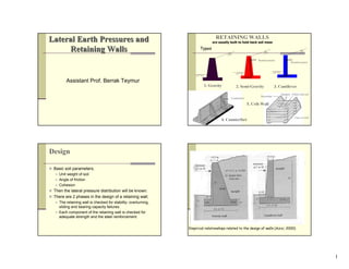
- 1. 1 Lateral Earth PressureLateral Earth Pressuress andand Retaining WallsRetaining Walls Assistant Prof. Berrak Teymur RETAINING WALLS are usually built to hold back soil mass 1. Gravity 2. Semi-Gravity Types 3. Cantilever Reinforcement Reinforcement Counterfort 4. Counterfort Strectcher Headers Filled with soil Face of wall 5. Crib Wall Design Basic soil parameters; Unit weight of soil Angle of friction Cohesion Then the lateral pressure distribution will be known. There are 2 phases in the design of a retaining wall; The retaining wall is checked for stability: overturning, sliding and bearing capacity failures. Each component of the retaining wall is checked for adequate strength and the steel reinforcement. Empirical relationships related to the design of walls (Azizi, 2000)
- 2. 2 Lateral Earth Pressure γ0 2 0210 2 1 KHHqKPPP +=+= At Rest q H z σh γ c φ K0 q K0 (q+γH) 1 2 P1 P2 P0 H/3 H/2 z' K0: coefficient of at- rest earth pressure The total force: uK vh +′= σσ 0 where φsin10 −=K for normally consolidated soil 0 21 32 P H P H P z + =′ σv If the water table is located at depth z<H, the at-rest pressure diagram will be as shown. H z γ c φ q γsat c φ GWT H1 H2 K0 q K0 (q+γH1) K0 (q+γH1+γH2) γwH2 u σ′h γ´=γsat-γw At z=0, σ´h=K0σ´v=K0q At z=H1, σ´h=K0σ´v=K0(q+γH1) At z=H2, σ´h=K0σ´v=K0(q+γH1+γ'H2) 2 2 2 20210 2 10100 2 1 ' 2 1 )( 2 1 HHKHHqKHKqHKP ωγγγγ +++++= Rankine Active Earth Pressure ∆x 45+φ/245+φ/2 Wall movement to left H z γ c φ z σh σv Rotation of wall about this point The Mohr’s circle will touch the Mohr-Coulomb failure envelope representing the failure condition in the soil mass. σh=σa, where σa is the Rankine active pressure. The Mohr-Coulomb failure envelope is defined by; τ = c + σ tanφ Relating the principal stresses for a Mohr’s circle that touches the Mohr-Coulomb failure envelope; ++ += 2 45tan2 2 45tan2 31 φφ σσ c σ1=σv and σ3=σa Thus ++ += 2 45tan2 2 45tan2 φφ σσ cav σa=σvKa-2c aK where Ka=tan2(45-φ/2); Rankine active pressure coefficient However the active earth pressure condition will be reached only if the wall is allowed to ‘yield’ sufficiently. The amount of outward displacement of the wall necessary is about 0.001H to 0.004H for granular soil backfills and about 0.01H to 0.04H for cohesive backfills.
- 3. 3 Coulomb’s Active Earth Pressure W Pa R β-δ θ1-φ β is the angle, the back face of the retaining wall makes with the horizontal. α is the angle that the backfill makes with the horizontal. δ is the angle of friction between the soil and the wall. The active force per unit length of the wall, Pa will be inclined at an angle of δ to the normal to the back face of the wall. 2 2 1 HKP aa γ= H: height of wall The value of the wall friction angle, δ is between φ/2 and 2φ/3. Rankine Passive Earth Pressure pK ∆x 45-φ/2 45-φ/2 Direction of wall movement H z γ c φ z Rotation of wall about this point σh σv The horizontal stress σh at this point is referred to as the Rankine passive pressure, σp=σvKp+2c where Kp=tan2(45+φ/2); Rankine passive earth pressure coefficient Rankine Passive Earth Pressure The magnitude of the wall movements, ∆x required to develop failure under passive conditions are; Soil Type ∆x (for passive condition) Dense sand 0.005H Loose sand 0.01H Stiff clay 0.01H Soft clay 0.05H
- 4. 4 pp KHP 2 2 1 γ= 2 2 2 )sin()sin( )sin()sin( 1)sin(sin )(sin ++ ++ −+ − = αβδβ αφδφ δββ φβ pK Coulomb’s Passive Earth Pressure Kp: Coulomb’s passive pressure coefficient Range of Wall Friction Angle Backfill materialδ(º) Gravel 27-30 Coarse sand 20-28 Fine sand 15-25 Stiff clay 15-20 Silty clay 12-16 α α γ c=0 φ σa α Pa H z H/3 α φαα φαα cos coscoscos coscoscos 22 22 −+ −− =aK aa zKγσ =aa KHP 2 2 1 γ= Rankine Active and Passive Earth Pressure for Inclined Granular Backfill pp KHP 2 2 1 γ= α φαα φαα cos coscoscos coscoscos 22 22 −− −+ =pK α α PA H H’ H/3 Ws WC Cantilever α α PA H H’ H/3 Ws WC Gravity Application of Lateral Earth Pressure Theories to Design Retaining Wall Stability 1) Safety Against Overturning (Rotational stability) : PV PH PAWc Ws C B Consider forces WC, WS, PV, PH Take moment w.r.t ‘C’ (TOE) clockwise : resisting (MR) (WC, WS, PV) a.clockwise :overturning (MO) (PH) if not increase the base ‘B’ ;use piles ;increase wall dimensions. Fs=2 (for cohesive backfill) and 1.5 (for granular backfill)
- 5. 5 Retaining Wall Stability 2) Safety Against Base Sliding : PV PH PAWc Ws B α D1 R c2,φ2,γ2 c1,φ1,γ1 D Driving Force : PH Ignore : PV Resisting force :R 5.1 cos tan)( tan)( 22 22 ≥ +Σ+ = +Σ+= α φ φ A p p P PVBc Fs PVBcR If base key : use reduced c2 and φ2 (φdesign=(0,5~0,67) φ2 , cdesign= =(0,5~0,67) c2) if not increase B ; provide key ;stronger backfill (import soil ∴ expansive) ; install tiedown anchors ppp KDcKDP 12 2 12 2 2 1 += γ Install tiedown anchors(if φ large) Extend heel Provide key Use stronger backfill Install tieback anchors 3) Bearing capacity failure. Fs=3=qu/qmax Base Pressures : PV PH PAWc Ws B A qall : allowable bearing capacity of foundation soil qmax qmin B A B/2 x ΣV e Sum of vertical forces Wc+Ws+Pv qmin > 0 (no tension) qmax < qall ) 6 1( 1* 2 min max B e B V q x B e V MM x DR ± Σ = −= Σ Σ−Σ = 4) Deep Seated Shear Failure : Weak soil Possible failure surface CONVENTIONAL ANALYSIS 5) CHECK FOR SETTLEMENTS (Conventional) : 6) REINFORCEMENT DESIGN (Structural Design) :
- 6. 6 Comments Relating to Stability The lateral force of the backfill will depend on (Casagrande, 1973); Effect of temperature (freeze and thaw), Groundwater fluctuation, Readjustment of the soil particles due to creep and prolonged rainfall, Tidal changes, Heavy wave action, Traffic vibration, Earthquakes. Gravity Retaining-Wall Design for Earthquake Conditions Coulomb’s active earth pressure theory can be extended to take into account the forces caused by an earthquake. H Pae δ β α γ c=0 φ kvW khW W φ .. ,. .. g compaccEQvertical k ggravitytodueacc compaccEQhorizontal k v h = = 2 2 2 2 )sin()sin( )sin()sin( 1)sin(sincos )(sin )1( 2 1 +−− −−+ +−− −+ = −= βαθδβ αθφδφ δθββθ θβφ γ AE vAE K KkHP AE − = − v h k k 1 tan 1 θ ~0,6H 0,5H Drainage from the Backfill of the Retaining Wall Bowles, 1997 Sheet Pile Walls are widely used for both large and small waterfront structures. used for Beach erosion protection Stabilizing ground slopes Shoring walls of trenches and other excavations and for cofferdams.
- 7. 7 Sheet Pile Walls Types: Wooden Precast concrete Steel b) Ball and socket type Sheet pile connections: a) Thumb and finger type Sheet Piles can be categorised as: a) Cantilever b) Anchored Construction Methods: 1. Backfilled structure 2. Dredged structure Sheet Pile Walls Cantilever Sheet Pile Walls -Used for small retaining height (20 ft ≅ 6 m above dredge line) Permanent : sands, gravels Temporary : other soils -Stability of cantilever sheet pile wall : due to passive resistance developed below the lower soil surface Cantilever Sheet Pile Walls Failure mode Dredge line 0 00 Active Active Active PassivePassive Passive h d R *fixing moment at 0 Design Idealisation Net Passive Resistance below ‘0’ : given with ‘R’ . ⇒ design : Σ Mc= 0 → determine ‘d’. Then ‘d’ is increased arbitrarily by %20 to allow for simplification of procedure . (1.2d : embedment) Σ Fh= 0 → determine R ( Check Pp ≥ R / over 0,2d ) Anchored Sheet Pile Walls Additional support to sheet pile walls can be given by backs (anchored) near the top of the wall (Used in deep excavation & water front construction ). Tie Rod (steel cables) ActivePassive h d A Bending Moment Diagram Note: depth of tension crack < depth of tie.
- 8. 8 Anchored Sheet Pile Walls DESIGN PROCEDURE: 1- Calculate Active & Passive Pressures in terms of (unknown) depth of embedment , ‘d’ . 2- Usually Fs=2 is applied to passive pressures 3- Take ΣMA =0 ; obtain cubic equation in terms of ‘d’. Solve for ‘d’. Increase d by 20% in quay walls. 4- Take ΣFh=0 ; solve for T. 5- Plot moment diagram & determine maximum bending moment. Determine required cross section. Sheet Piles with Anchors Anchor Active Passive h d A Moment Diagram When there is a deep excavation 0 Passive Active Passive A 0 R Active Note: Solved with equivalent beam method. Types of anchor used in sheet pile walls are: 1. Anchor plates and beams 2. Tie backs 3. Vertical anchor piles 4. Anchor beams supported by batter (compression and tension) piles Das, 1995 Das, 1995
- 9. 9 Systems to support the sides of excavations To support walls of deep or shallow narrow trenches. Side view Top view Sheet piling struts wales Braced Cuts (Braced Excavations) EARTH PRESSURES AGAINST BRACING SYSTEMS Braced Cuts: Earth Pressure function of Wall Displacement: Represented by empirical pressure envelopes Bracing systems ACTIVE (Retaining walls) Fixed TERZAGHI & PECK (1967) EMPIRICAL PRESSURE DIAGRAMS 0,25 H 0,50 H 0,25 H 0,75 H 0,25 H γ φ (sand) cu (clay) H 0.65 KA γ H medium to dense SAND 0.2 γ H to 0.4 γ H Stiff CLAY γ H KA soft to medium CLAY H c mKA γ 4 1−= 1 32 TERZAGHI & PECK (1967) EMPIRICAL PRESSURE DIAGRAMS uc Hγ 1) 0,65 Times Rankine Active 2) N:stability number N= if N < 4 (elastic equilibrium) 3) N > 4 plastic equilibrium at the bottom ( N=γH/cu > 4) m is usually 1,0 , but m=0,4 for soft NC clays. 4) N > 7 Heaving Strut Loads: A B C D HINGES to make the system determinant A B1 C1 D B2 C2 A=A B=B1+B2 C=C1+C2 D=D A,B,C,D Strut Loads Braced Cuts Wall construction & anchorage installation in stages. R/C wall anchor 1 5432 REINFORCED EARTH Reinforced earth is a construction material comprising soil that has been strengthened by tensile elements such as metal rods and/or strips, nonbiodegradable fabrics (geotextiles), geogrids. The beneficial effects of soil reinforcement derive from a) soil’s increased tensile strength and b) the shear resistance developed from the friction at the soil-reinforcement interfaces.
- 10. 10 REINFORCED EARTH Geotextiles have four primary uses in foundation engineering: 1. Drainage 2. Filtration 3. Separation 4. Reinforcement – increases the load-bearing capacity of the soil REINFORCED EARTH Two types of geogrids: a) Biaxial and b) Uniaxial 1.Longitudinal rib 2.Transverse bar 3.Transverse rib 4. Junction REINFORCED EARTH Facing (flexible) Footing Fill Coarse grained soil (drained) Reinforcement (tensile stresses) *steel : life 120 years *other materials; -aluminium alloys -plastics -geotextiles FACING : *Pre-cast concrete units (limited relative movement) *U-shaped steel sections arranged horizontally COST : *more economic than concrete cantilever retaining wall FAILURE : *Tensile failure of one element leads to progressive collapse of the entire structure *Local slipping leads to redistribution of tensile stress and gradual deformation of structure (not necessarily collapse) PASSIVE Zone RESISTANCE ACTIVE Zone 0,3H C A B 0,5H LeLv H z Max. tensile stress curve ≅Probable failure surface At-rest Active Lateral Earth Pressure p REINFORCED EARTH