طلمبات تعزيز الضغط - أنظمة متكاملة
•
1 like•143 views

أنظمة تعزيز الضغط تعمل آليا بشكل كامل و هى المثلى لعمليات إمدادات المياه للتطبيقات الصناعية, التجارية وأنظمة الرى فقد يتضمن النظام الواحد حتى أربعة طلمبات, تعمل بتدفق حتى 640 متر مكعب/ساعة حتى 160 متر وتتحمل حرارة السوائل المضخة حتى 80 درجة مئوية http://rheoserve.com/booster_sets.html

Recommended
Recommended
More Related Content
What's hot
What's hot (16)
Similar to طلمبات تعزيز الضغط - أنظمة متكاملة
Similar to طلمبات تعزيز الضغط - أنظمة متكاملة (20)
More from Rheoserve Industrial Solutions
More from Rheoserve Industrial Solutions (20)
Recently uploaded
Recently uploaded (20)
طلمبات تعزيز الضغط - أنظمة متكاملة
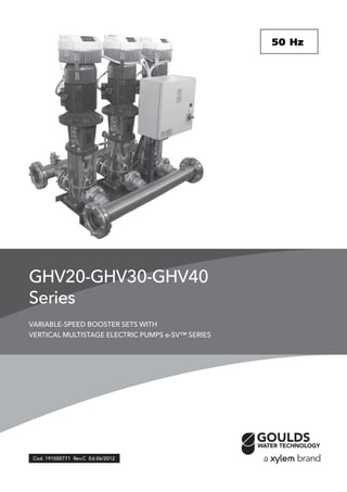
- 1. GHV20-GHV30-GHV40 Series VARIABLE-SPEED BOOSTER SETS WITH VERTICAL MULTISTAGE ELECTRIC PUMPS e-SV™ SERIES CCCCCod.od.od.od.od. 191000771 R191000771 R191000771 R191000771 R191000771 Revevevevev.C Ed.06/2012.C Ed.06/2012.C Ed.06/2012.C Ed.06/2012.C Ed.06/2012 50 Hz50 Hz50 Hz50 Hz50 Hz
- 2. 2 General introduction .............................................................................................................................33333 Choice and selection..............................................................................................................................77777 GHVGHVGHVGHVGHV.../SV.../SV.../SV.../SV.../SV Series .............................................................................................................................2525252525 Range ...............................................................................................................................................2727272727 Characteristics of the electric pumps .............................................................................................2828282828 Hydraulic performance tables ...........................................................................................................3333333333 Electric data tables............................................................................................................................4242424242 GHV20 Series ...................................................................................................................................4545454545 GHV30 Series ...................................................................................................................................5959595959 GHV40 Series ...................................................................................................................................7575757575 Operating characteristics at 30..50 Hz .............................................................................................9090909090 Hc pressure drop curve ................................................................................................................113113113113113 Accessories ..................................................................................................................................117117117117117 Technical Appendix ......................................................................................................................121121121121121 CONTENTSCONTENTSCONTENTSCONTENTSCONTENTS
- 3. 3 BOOSTER SETS GHV SERIESBOOSTER SETS GHV SERIESBOOSTER SETS GHV SERIESBOOSTER SETS GHV SERIESBOOSTER SETS GHV SERIES GENERAL INTRODUCTION - PRODUCT DESCRIPTIONGENERAL INTRODUCTION - PRODUCT DESCRIPTIONGENERAL INTRODUCTION - PRODUCT DESCRIPTIONGENERAL INTRODUCTION - PRODUCT DESCRIPTIONGENERAL INTRODUCTION - PRODUCT DESCRIPTION GHV series booster sets are designed to transfer and increase the pressure of water, in the following applications: • Hospitals • Schools • Public buildings • Industries • Hotels • Condominiums • Sports facilities • Mains water systems GHV series booster sets are pumping stations assembled with two up to a maximum of four vertical multistage pumps from the e-SV series. The pumps are connected to one another by suction and delivery pipes, and fixed onto a single base. The pumps are connected to the manifolds by means of stop valves and check valves. An electric protection and control panel is installed using a bracket on the base of the set. GHV series booster sets offer different regulating possibilities and are divided into the following versions: GHV Multi - Master seriesGHV Multi - Master seriesGHV Multi - Master seriesGHV Multi - Master seriesGHV Multi - Master series Pressure boosting sets with 2 to 4 e-SV series pumps, with Hydrovar® Master-type frequency converters for each pump located on the booster set. Variable speed operation is possible on all pumps turning at the same speed. GHV Master + Basic seriesGHV Master + Basic seriesGHV Master + Basic seriesGHV Master + Basic seriesGHV Master + Basic series Pressure boosting sets with 2 to 4 e-SV series pumps, with Hydrovar® Master-type or Basic-type frequency converters for each pump located on the booster set. Further details on page 15. Variable speed operation is possible on all pumps turning at the same speed. GHC Cascade control seriesGHC Cascade control seriesGHC Cascade control seriesGHC Cascade control seriesGHC Cascade control series Pressure boosting sets with 2 to 4 e-SV series pumps, one single pump equipped with a Hydrovar® frequency converter. Further details on page 16. All the other pumps kick-in depending on system requirements and run at fixed speed. The constant pressure is maintained by adjusting the speed on the Hydrovar® pump. Systems for regulating the speed of the electric motors, as in GHV series booster sets, are used in the following cases: • In the case of systems with a lot of users where the daily consumption varies frequently and in different periods. • When it is necessary to obtain constant pressure. • In the case of systems with supervision it is possible to monitor and check the performances of the pump stations. Systems for regulating the speed of the electric motors, as in GHV series booster sets, are used in the following cases: • In the case of systems with a lot of users where the daily consumption varies frequently and in different periods. • When it is necessary to obtain constant pressure. • In the case of systems with supervision it is possible to monitor and check the performances of the pump stations. These types of systems improve comfort for the final user, reducing noise output and guarantee the reduction of the so-called “water hammer”, thanks to the gradual switching off of the pumps.
- 4. 4 BOOSTER SETS GHV SERIESBOOSTER SETS GHV SERIESBOOSTER SETS GHV SERIESBOOSTER SETS GHV SERIESBOOSTER SETS GHV SERIES DESCRIPTION OF OPERADESCRIPTION OF OPERADESCRIPTION OF OPERADESCRIPTION OF OPERADESCRIPTION OF OPERATIONTIONTIONTIONTION In GHV series booster sets all pumps operate at variable speed. The pumps are connected to a frequency converter assembled directly on the motor fan cover. All pumps, to a maximum of four, engage by means of their own frequency converter. The pumps start automatically depending on the system requirements. Each pump is fitted with a pressure transmitter that is required to detect the pressure variation. The recorded figure is transmitted to the frequency converter. The pump driven by the inverter modulates its speed according to the system demand. The alternating pump start takes place automatically whenever the system is started and at pre-set timings. Starting and stopping of the pumps is determined according to the set value of pressure in the frequency converter menu. Example of operation of a set of three GHV series pumps.Example of operation of a set of three GHV series pumps.Example of operation of a set of three GHV series pumps.Example of operation of a set of three GHV series pumps.Example of operation of a set of three GHV series pumps. The pumps are controlled by each frequency converter connected directly to the pump electric motor; at every new starting cycle of the pumps, the starting priority of the pumps changes. The speed adjustment will be for all installed pumps. All the pumps will turn at the same speed. When the demand for water decreases, the pumps will stop in cascade. The pumps connected to the frequency converters keep the pressure constant by modulating the number of motor revs. At start and stop all pumps have a soft acceleration and deceleration. This allows to reduce water hammers and provide low booster set noise output. GHV series booster sets guarantee constant pressure of the system as in the following example: Example of operation of a set of three GHC series pumps.Example of operation of a set of three GHC series pumps.Example of operation of a set of three GHC series pumps.Example of operation of a set of three GHC series pumps.Example of operation of a set of three GHC series pumps. One pump is controlled by a Master-type frequency converter connected directly to the pump electric motor. The other pumps are controlled by an external ON/OFF signal and run at fixed speed. Speed adjustment happens only for the pump connected to the frequency converter. The other starting pumps use the contactors in the electric panel. The pump connected to the frequency converter will start first, while the other pumps will follow. For the latter it is possible to have the automatic alternating start in order to distribute the working load evenly. When the demand for water decreases, the pumps will stop in cascade. The last to stop will be the inverter pump. The constant pressure is maintained by adjusting the speed of the first pump. Set pressure H Q
- 5. 5 When there is a demand for water, the pump controlled by the converter will start, positioning its speed to guarantee the set pressure value. When the demand for water increases, the other pumps will start operating at variable speed and with the same speed value in order to maintain a constant pressure. When the demand for water decreases, the pumps switch off in cascade and the first pump decreases the number of revs to a set minimum before switching off definitively. Regulating the constant pressure valueRegulating the constant pressure valueRegulating the constant pressure valueRegulating the constant pressure valueRegulating the constant pressure value GHV series booster sets guarantee constant pressure of the system even during frequent variations in water consumption. When the booster set is connected to the system, the pressure value is read through the pressure transducers fitted on the delivery manifold. The value found is compared with the set value. The check between the pressure value found and the set value is made by means of the Hydrovar® internal “controller” that manages the motor acceleration and deceleration ramps (frequency), modifying the pump performance over time. In case of malfunction of one of the frequency converters, the other will continue to stay active and guarantee the control of the other pumps as well as maintain a constant pressure. Type of controlType of controlType of controlType of controlType of control GHV series booster sets use a sensor as a standard device to control pressure. For each booster set the sensor number is the same as the number of installed pumps. In case of fault in the transducer the converter connected to the pump stops operating. It is possible to change the measuring unit as bar, psi, m3 /h, °C, °F, l/sec, l/min, %. In this case it is possible to use different transducers depending of the selected measuring unit, such as flow and temperature transducers. SetpointSetpointSetpointSetpointSetpoint It is possible to select up to two setpoints of different values. Thus it is possible to use the booster set to serve systems that require different user pressure values. For example, different setpoints can be used for an irrigation system on a hillside, or one setpoint value can be used for domestic water supply during the day and a second setpoint for irrigation at night. The setpoint changes can be made using an external device. Set pressure H Q BOOSTER SETS GHV SERIESBOOSTER SETS GHV SERIESBOOSTER SETS GHV SERIESBOOSTER SETS GHV SERIESBOOSTER SETS GHV SERIES DESCRIPTION OF OPERADESCRIPTION OF OPERADESCRIPTION OF OPERADESCRIPTION OF OPERADESCRIPTION OF OPERATIONTIONTIONTIONTION
- 6. 6 Cyclical exchange of pumpsCyclical exchange of pumpsCyclical exchange of pumpsCyclical exchange of pumpsCyclical exchange of pumps Cyclical exchange of pumps is available for both the GHV and the GHC series. For the GHV series the pumps equipped each with its own drive alternate the start at every system restart or at a given time set for each pump by means of an internal clock in the drive menu. For the GHC series, the cyclical exchange takes place only for fixed-speed pumps that are controlled by their dedicated electric panel. The pump connected to the drive always starts first. Protection against dry runningProtection against dry runningProtection against dry runningProtection against dry runningProtection against dry running The protection function against dry running intervenes if the water reserve to which the booster set is connected falls below the minimum level guaranteed for suction. For GHV series booster sets the level may be controlled by a float, level probes or minimum pressure switch. It is also possible to manage the function directly by imputing a minimum pressure value in the Hydrovar® control board menu, which will receive a signal from the pressure transducer. BOOSTER SETS GHV SERIESBOOSTER SETS GHV SERIESBOOSTER SETS GHV SERIESBOOSTER SETS GHV SERIESBOOSTER SETS GHV SERIES DESCRIPTION OF OPERADESCRIPTION OF OPERADESCRIPTION OF OPERADESCRIPTION OF OPERADESCRIPTION OF OPERATIONTIONTIONTIONTION
- 7. 7 BOOSTER SETS GHV SERIESBOOSTER SETS GHV SERIESBOOSTER SETS GHV SERIESBOOSTER SETS GHV SERIESBOOSTER SETS GHV SERIES CHOICE AND SELECTIONCHOICE AND SELECTIONCHOICE AND SELECTIONCHOICE AND SELECTIONCHOICE AND SELECTION The following conditions should be considered when choosing a booster set: • The system’s requirements should be met regarding flow rate and pressure. • The booster set must not be oversized, avoiding unnecessary installation and running costs. Generally water distribution systems such as those for domestic water supply or for large agglomerates such as hospitals, hotels or similar, have “variable” water consumption i.e. in a 24-hour period there may be sudden variations in consumption that are difficult to foresee. A pattern of consumption may occur in 24 hours, but the daily percentage of booster set operation may also occur at various flow rates. Generally the definition of flow rate for these types of systems is based on either the “probability calculation” which is a very complex system of calculation, or based on tables or diagrams in the national standards which provide guidelines for the sizing of the systems and therefore for calculating the maximum simultaneous flow rate. The operating time of the booster set, still calculated over 24h, gives us a view of the daily percentage of operation at the various flow rates. This means that there may be daily peaks where the maximum flow rate requested is concentrated in a short space of time. In the example given below, it can be seen that in 100% of the time there is a consumption of 4 m³/h, while in 20% of the operating time there is a consumption of 40 m³/h. Consumption--over 24 h hours 3 6 129 15 18 21 24 Q (m³/h) 10 20 30 40 Operating time % hours/day20 50 75 100 Q (m³/h) 10 20 30 40
- 8. 8 When selecting the booster set the consumption figure of the system must be considered, which is generally supplied by the person who designed the system. For systems where consumption varies continuously and suddenly over time it is advisable to install GHV series booster sets with variable regulation of the pump speed. The calculation of the size of the booster set (its performance and the number of pumps) is based on the take-off point and therefore on the consumption value which takes the following factors into account: • The value of the peak in consumption • Efficiency • NPSH • Standby pumps • Jockey pumps • Diaphragm tanks By adjusting their operation over time, variable-speed booster sets give the end user energy savings which can be calculated directly on the control board with a metering module fitted in the electric panel. This allows checking of the system efficiency, especially in complex systems with many users and many ranges of consumption. It is possible to install a standby pump if it is necessary to have some kind of additional safety in the pump station. This is typical in systems of a certain importance, such as hospitals or factories, or in the field of crop irrigation. If small users have to be served in the same system, it is preferable to install what is commonly called a jockey pump, where instead of running the main pump, which usually has higher power, the service is guaranteed with a smaller pump and therefore lower energy consumption. GHV series booster sets must also be equipped with diaphragm tanks (for the size of the tank, see the specific chapter in this catalogue). A single tank can be installed on the delivery side of the booster set, or smaller tanks, maintaining the same total volume. Diaphragm tanks avoid the risk of water hammer, which is harmful for both the system and the pumps. Generally for systems with highly variable or sudden variations in consumption, it is recommended to install a booster set with variable pump speed, such as the GHV series, to guarantee constant pressure. SELECTING THE PUMPSSELECTING THE PUMPSSELECTING THE PUMPSSELECTING THE PUMPSSELECTING THE PUMPS What type of pump to choose? Generally, the choice of pump is based on the take-off point of the system, which is usually the highest possible. The maximum request value is normally for short periods, so the pump must also be able to satisfy variable requests throughout its time in service. BOOSTER SETS GHV SERIESBOOSTER SETS GHV SERIESBOOSTER SETS GHV SERIESBOOSTER SETS GHV SERIESBOOSTER SETS GHV SERIES CHOICE AND SELECTIONCHOICE AND SELECTIONCHOICE AND SELECTIONCHOICE AND SELECTIONCHOICE AND SELECTION
- 9. 9 BOOSTER SETS GHV SERIESBOOSTER SETS GHV SERIESBOOSTER SETS GHV SERIESBOOSTER SETS GHV SERIESBOOSTER SETS GHV SERIES SELECTING THE PUMPSSELECTING THE PUMPSSELECTING THE PUMPSSELECTING THE PUMPSSELECTING THE PUMPS Generally the choice of the pump, based on the performance curve, should fall around the maximum efficiency point. The pump must ensure operation within its rated performance. Since the booster set is sized according to the maximum possible consumption, the take-off point of the pumps must be in the area on the right of the performance curve so that, if there is a fall in consumption, the efficiency remains high. If we make a choice on the characteristic curve of the pump, we can see that the area where it is best to select the pump is represented by the following graph: Another factor to be considered when choosing the pumps is its npsh value. Never choose a pump where the take- off point is too far to the right of the npsh curve. This risks not having good pump suction, which may be aggravated by the type of installation (where negative suction is possible). In these cases there is the risk of cavitation. The npsh of the pump must always be checked at the maximum flow rate requested. Pump performance curve Q η Recommended range npsh Q ÷Recommended range Npsh curve Recommended selection area H Q
- 10. 10 H[m] 0 20 40 60 80 100 120 140 160 180 Q [US gpm] 0 100 200 300 400 500 H[ft] 0 100 200 300 400 500 Q [Imp gpm] 0 100 200 300 400 Q [m3 /h]0 20 40 60 80 100 120 140 NPSH[m] 0 2 4 6 Q [l/min]0 500 1000 1500 2000 NPSH[ft] 0 5 10 15 77082_A_CH 22SV10 ISO 9906 - Annex A 1 P 2 P 3 P 4 P The choice of pump is therefore based on the characteristic curve of the pump depending on the flow rate and the pressure required for the system. Starting from the required flow rate, a vertical line is drawn until it meets the horizontal line of the required pressure. The point of intersection of the lines gives both the type and the number of pumps necessary for the system. The example alongside refers to a required flow rate of 60 m³/h and a pressure of 110 water column. As may be seen from the selection, the system requires three pumps of the type 22SV10 as indicated top left in the table. Moreover the take-off point falls in the npsh area farthest to the left and therefore in an area with a low cavitation risk. The values obtained are those for the performance of the pumps. A correct check of the net pressure value must be made due to the intrinsic load loss of the booster set and the conditions of installation. For this reason it is recommended to see the specific chapter in this catalogue. BOOSTER SETS GHV SERIESBOOSTER SETS GHV SERIESBOOSTER SETS GHV SERIESBOOSTER SETS GHV SERIESBOOSTER SETS GHV SERIES SELECTING THE PUMPSSELECTING THE PUMPSSELECTING THE PUMPSSELECTING THE PUMPSSELECTING THE PUMPS
- 11. 11 H[m] 0 20 40 60 80 100 120 140 160 180 Q [US gpm] 0 100 200 300 400 500 H[ft] 0 100 200 300 400 500 Q [Imp gpm] 0 100 200 300 400 Q [m3 /h]0 20 40 60 80 100 120 140 NPSH[m] 0 2 4 6 Q [l/min]0 500 1000 1500 2000 NPSH[ft] 0 5 10 15 77082_A_CH 22SV10 ISO 9906 - Annex A 1 P 2 P 3 P 4 P When selecting the GHV series of pressure booster units, reference must be made to pump performance. Performance is calculated from the characteristic curves of the pumps and does not consider any pressure drops generated by pipes and valves as in the pressure booster units. To help choose the right pressure booster unit and calculate the correct pressure at the delivery manifold, the following example is shown: given the duty point Q = 42 m3 /h H = 105 mca and with two pumps working, the pump with the most suitable characteristic curve is chosen, that is, the one with a curve that guarantees the required flow and head values. From the example, we have chosen the 22SV10 series pump which guarantees system performance. The pump curve is slightly oversized, but this provides a safety margin to counter the pressure drops in the pressure booster unit pipes. To know the effective pressure at the delivery manifold outlet, the pressure drops in the suction and delivery lines of each pump are calculated. To simplify calculations, the pressure drop curves for each pump, on page 113 of this catalogue, are used. Assuming a pressure booster unit with check valves on the suction line (curve B of Hc pressure drops) has been selected, one proceeds as follows: The Hc pressure drops on the pump suction line are to evaluated on the “B” curve. At a flow rate of 21 m3 /h the value of Hc = 2,8 m. Similarly, the Hc pressure drops on the delivery line of the pump, as evaluated on the “B” curve, are analysed. At a flow rate of 21 m3 /h, the value of Hc is 0,035 m. The total pressure drop on the delivery and suction lines is therefore 2,84 m. As regards the pressure drop in the suction and delivery manifolds, 5% with respect to the pressure drops in the pump suction and delivery can be considered. In this case, therefore, the value is 0,142 m. The total pressure drop is approximately: 3 m. Analysing the performance of the unit at a flow rate of 42 m3 /h, the head H is 115 m. The net pressure at the delivery manifold is 115 – 3 = 112 m. Comparing this value with the rated value, 112 m > 105 m. The unit can therefore satisfy the demand of the system. BOOSTER SETS GHV SERIESBOOSTER SETS GHV SERIESBOOSTER SETS GHV SERIESBOOSTER SETS GHV SERIESBOOSTER SETS GHV SERIES CALCULACALCULACALCULACALCULACALCULATING NET PRESTING NET PRESTING NET PRESTING NET PRESTING NET PRESSURESURESURESURESURE
- 12. 12 The above example does not consider the suction conditions of the pressure booster unit which, similarly, affect final performance. It is therefore always best to check the suction line for leaks, especially as regards positive head installations. An example of positive head installation relative to the above case is shown below: In the positive head installation, the designer must calculate the minimum installation height Hg of the pump in safety conditions in order to avoid cavitation and, therefore, de-priming of the pump. The relationship that must be checked and which connects this measurement is the following: NPSH available ≥ NPSH requested where equality is the limit condition. NPSH available = Patm + Hg - ∑ pressure drops. Where: Patm is the atmospheric pressure, equal to 10,33 m Hg is the geodetic difference in level The pressure drops are connected with to the suction piping and relative valves (foot and cut-off valves) NPSH requested is a pump parameter taken from the performance curve of the pump which in our case, at a flow rate of 21 m3 /h corresponds to 2,5 m. Before calculating the NPSH available, the suction pressure drops are calculated using the tables on pages 131-132 in this catalogue, considering a material such as steel. The chosen diameter of the suction piping is DN80. 90° curve DN80 = 2,11 m Damper DN80 = 0,28 m Drain valve DN80 = 0,3 m (calculated from supplier data) Piping DN80 = 0,61 m (assuming a length of 2,5 m) Piping DN80, intake manifold = 0,04 m (length of manifold 0,61 m) Pressure drops on pump suction side (curve B) = 2,8 m ∑ pressure drops = 6,1 m Remembering that: NPSH available = 10,33 + Hg - 6,1 Replacing: 10,33 + Hg - 6,1 ≥ 2,5 Hg = 2,5 + 6,1 – 10,33 = - 1,73 m representing the limit, for which reason: NPSH available = NPSH requested Generally speaking, therefore, in order to assure correct operating conditions as regards the risk of cavitation, the pump must be positioned above the level of the tank so that the suction height is lower than the limit value of 1,73 m. BOOSTER SETS GHV SERIESBOOSTER SETS GHV SERIESBOOSTER SETS GHV SERIESBOOSTER SETS GHV SERIESBOOSTER SETS GHV SERIES SUCTION CONDITIONSSUCTION CONDITIONSSUCTION CONDITIONSSUCTION CONDITIONSSUCTION CONDITIONS
- 13. 13 BOOSTER SETS GHV SERIESBOOSTER SETS GHV SERIESBOOSTER SETS GHV SERIESBOOSTER SETS GHV SERIESBOOSTER SETS GHV SERIES INSTINSTINSTINSTINSTALLAALLAALLAALLAALLATIONTIONTIONTIONTION GHV series booster sets must be installed in areas protected against frost and with adequate ventilation to cool the motors. It is good practice to connect the suction and delivery pipes with vibration-damping joints to limit vibrations and resonance in the whole system. GHV series booster sets must be connected to pressurised tanks with an adequate capacity for the system. These tanks can avoid any problems due to water hammer that is created due to the sudden stopping of the pumps running at a fixed speed. For this type of system, 24-litre diaphragm tanks can be used that perform a pressure dampening function, since they do not have to provide water storage like ordinary autoclave systems. Due to their design, variable-speed booster sets can satisfy users’ demands by moderating the pump speed. It is always recommended to check the type of system to be made and choose the correct capacity of the diaphragm tank accordingly. For the sizing of the diaphragm tanks, see the specific chapter in this catalogue. Considering also that variable-pressure sets are very sensitive to swings of pressure in the system, the use of diaphragm tanks allows the pressure to stabilise when requests are low or inexistent, and avoids the pumps remaining in operation at minimum speed without stopping. It is good practice to check the value of the maximum pump pressure to match the set with a tank suitable for the pressure value. Delivery anti-vibration joint Suction Suction Delivery
- 14. 14 SET IDENTIFICASET IDENTIFICASET IDENTIFICASET IDENTIFICASET IDENTIFICATION CODETION CODETION CODETION CODETION CODE 30 / 22SV02F022T / DW Electric pump. See table. 20 = 2 pumps. 30 = 3 pumps. 40 = 4 pumps. Series name. PA/ Options _ = Standard version. DW = Drinking water version. A304 = Special version AISI 304. A316 = Special version AISI 316. GHV RA Non-return valve. _ = Delivery side. RA = Suction side. / M _ = Three-phase (over 2,2 kW). T = Three-phase (up to 2,2 kW). M = Single-phase (up to 2,2 kW). OPTIONS (ON DEMAND)OPTIONS (ON DEMAND)OPTIONS (ON DEMAND)OPTIONS (ON DEMAND)OPTIONS (ON DEMAND) 2S Hydrovar® equipped with double sensor. 3A Booster set with electric pump certified 1A (Factory test reports issued by the end of assembly line; it includes QH curve). 3B Booster set with electric pump certified 1B (Test report issued by Audit Test Lab; it includes QH curve, efficiency and power). 60 Booster set with 60Hz supply voltage. BAP High pressure switch installed on the delivery manifold. BF Hydrovar® equipped with “B” filter for for three-phase supply; domestic environment. C9 Delivery manifold at 90° with bend. The expansion vessels cannot be installed directly on the manifold. CM Suction or delivery manifold larger than standard size. CP Clean contacts version: converter faulty, start/stop for each pump. HFD Hydrovar® and panel mounted delivery side (for wall mounted version Hydrovar®), available only up to 22kw power. Beyond this size, the control panel will be wall mounted WM and the Hydrovar® will be wall mounted HWM. HFS Hydrovar® and panel mounted suction side (for wall mounted version hydrovar). HWM Wall mounted hydrovar , cables lenght = 5 m. IP65 IP65 version control panel. KV Kit voltmeter. MA Pressure gauge installed on suction manifold. NL Dutch market version. PA Minimum pressure gauge installed on the suction manifold for dry-running protection. PQ Booster set with higt suction pressure (pressure gauge/pressure switches/pressure transmitter increased of one range). RA Non return valves mounted on suction side (Es. GHV20RA/SV…). RE Heaters inside the control panel, with thermostat. SA No intake: no suction valves and suction manifold. SC Group with no control devices, such as pressure switches and transmitters; the pressure gauge is present. SCA No suction manifold (suction valves present). SCM Without delivery manifold (no pressure transmitters and pressure gauge, with delivery valves). SM Without delivery: without valves on delivery and without delivery manifold. TS Booster set with pumps equipped with special mechanical seals. UK UK market version. VA Electric control panel fitted with analogue voltmeter and ammeter. WM Wall-mounted electrical panel with fixing tabs. Cables L= 5m AAAAAVVVVVAILABLE VERSIONSAILABLE VERSIONSAILABLE VERSIONSAILABLE VERSIONSAILABLE VERSIONS A304 Main component in contact with liquid in stainless steel Aisi 304 or superior; gasket, sealing tape and thread sealing are suitable for drinking water. Bolts and screws galvanized. Flanges not in contact with the liquid in galvanized steel. B304 Main component in contact with liquid in stainless steel Aisi 304 or superior; gasket, sealing tape and thread sealing are suitable for drinking water. Bolts and screws in Aisi 304 or superior. Flanges not in contact with the liquid in Aisi 304 or superior. C304 Main component in contact with liquid in stainless steel Aisi 304 or superior; gasket, sealing tape and thread sealing are suitable for drinking water. Baseplate, frame, supports, bolts and screws in Aisi 304 or superior. Flanges not in contact with the liquid in Aisi 304 or superior. Valves and their components completely in Aisi 304 or superior (body, disc, plate). A316 Main component in contact with liquid in stainless steel Aisi 316; gasket, sealing tape and thread sealing are suitable for drinking water. Pumps in Aisi 316 material. Bolts and screws galvanized. Flanges not in contact with the liquid in galvanized steel. B316 Main component in contact with liquid in stainless steel Aisi 316; gasket, sealing tape and thread sealing are suitable for drinkingwater. Pumps in Aisi 316 material. Bolts and screws in Aisi 316. Flanges not in contact with the liquid in Aisi 316. C316 Main component in contact with liquid in stainless steel Aisi 316; gasket, sealing tape and thread sealing are suitable for drinking water. Pumps in Aisi 316 material. Baseplate, frame, supports, bolts and screws in Aisi 316. Flanges not in contact with the liquid in Aisi 316. Valves and their components completely in Aisi 316 (body, disc, plate). DW Main component in contact with fluid suitable for drinking water or in stainless steel AISI 304 or superior quality.
- 15. 15 VVVVVARIABLE-SPEED PUMP SYSTEMSARIABLE-SPEED PUMP SYSTEMSARIABLE-SPEED PUMP SYSTEMSARIABLE-SPEED PUMP SYSTEMSARIABLE-SPEED PUMP SYSTEMS From a mechanical standpoint, the Module conceptModule conceptModule conceptModule conceptModule concept related to HYDROHYDROHYDROHYDROHYDROVVVVVARARARARAR® is divided in two parts, the motormotormotormotormotor assemblyassemblyassemblyassemblyassembly power unit (power unit) and the control boardcontrol boardcontrol boardcontrol boardcontrol board. In the basic configuration, that is with a single motor assembly, HYDROVAR® may be used as “Basic Unit (BASIC)”“Basic Unit (BASIC)”“Basic Unit (BASIC)”“Basic Unit (BASIC)”“Basic Unit (BASIC)” without having to use a control board. In this configuration HYDROVAR® may be used as a sequential pump in a multi-pump system with at least one master inverter. By expanding the “Basic inverter” with the additional control board and the LCD screen, the HYDROVAR® “Master“Master“Master“Master“Master Unit”Unit”Unit”Unit”Unit” becomes suitable to operate in different modes and may be expanded by implementing several modules. GHV VERSION, MASTER + BASIC SERIESGHV VERSION, MASTER + BASIC SERIESGHV VERSION, MASTER + BASIC SERIESGHV VERSION, MASTER + BASIC SERIESGHV VERSION, MASTER + BASIC SERIES This mode provides several different combinations of different HYDROVAR® versions. In general, each pump is equipped with a HYDROVAR® unit. Each pump in the system (which may count up to 8 pumps), is fitted with a HYDROVAR® unit (at least one as “Master unit”“Master unit”“Master unit”“Master unit”“Master unit” and the others as “Basic units”“Basic units”“Basic units”“Basic units”“Basic units”, to guarantee adequate system control); the units are connected one another by means of a serial interface. Minimum requirements: one “Master unit” and the others equipped with “Basic unit”. The entire control process takes always place by means of the “Master unit”, though it is also possible to alternate the standby pump sequence in order to distribute wear and allow for the same number of operating hours of the pumps controlled by basic inverters. Following versions are available: • Power size above 2,2kW up to 11 kW motor mounted.Power size above 2,2kW up to 11 kW motor mounted.Power size above 2,2kW up to 11 kW motor mounted.Power size above 2,2kW up to 11 kW motor mounted.Power size above 2,2kW up to 11 kW motor mounted. General description of booster name: GHV [ ][ ]: First digit: total number of pump, Second digit: number of Basic units. Example: - GHV21GHV21GHV21GHV21GHV21: two pumps booster set, one “Master Inverter” and one “Basic Inverter” configuration. - GHV31GHV31GHV31GHV31GHV31: three pumps booster set, two “Master Inverter” and one “Basic Inverter” configuration. - GHV32GHV32GHV32GHV32GHV32: three pumps booster set, one “Master Inverter” and two “Basic Inverter” configuration. MASTER INVERTER BASIC INVERTER BASIC INVERTER BASIC INVERTER RS 485 CONNECTION GHV43/..GHV43/..GHV43/..GHV43/..GHV43/.. AAAAAVVVVVAILABLE SERIESAILABLE SERIESAILABLE SERIESAILABLE SERIESAILABLE SERIES GHV Multi-Master series. One Hydrovar® Master-type frequency converter for each electric pump. GHV Master + Basic series. One Hydrovar® frequency converter for each electric pump. Hydrovar® Master and/or Basic type. GHC GHC Cascade control series. Single Hydrovar® Master type frequency converter per set; the other electric pumps run at fixed speed, without a converter.
- 16. 16 GHC VERSION, CASCADE CONTROL SERIESGHC VERSION, CASCADE CONTROL SERIESGHC VERSION, CASCADE CONTROL SERIESGHC VERSION, CASCADE CONTROL SERIESGHC VERSION, CASCADE CONTROL SERIES One pump is equipped with a HYDROVAR® “Master unit”, while up to five fixed-speed pumps may be operated on request with the ON and OFF signal. For this purpose an additional 5-relay board is fitted on to the “Master unit”. It is necessary to resort to an external electric panel, in that the HYDROVAR® relays are not capable of directly commutating the pumps, since they are used exclusively as signal terminals. In this operating mode it is also possible to automatically alternate the fixed-speed pumps in order to distribute wear and allow the pumps to operate for the same number of hours. The inverter always feeds the same electric pump. The following power levels are available: • Power from 2,2kW to 22 kWPower from 2,2kW to 22 kWPower from 2,2kW to 22 kWPower from 2,2kW to 22 kWPower from 2,2kW to 22 kW, motor assembly (maximum 6 electric pumps), motor assembly (maximum 6 electric pumps), motor assembly (maximum 6 electric pumps), motor assembly (maximum 6 electric pumps), motor assembly (maximum 6 electric pumps) Example: - GHC20GHC20GHC20GHC20GHC20: pressure booster assembly made up of two pumps, a “Master inverter” and an electric pump running at fixed speed. - GHC30GHC30GHC30GHC30GHC30: pressure booster assembly made up of three pumps, a “Master inverter” and two electric pumps running at fixed speed. MASTER INVERTER EXTERNAL PANEL GHV VERSION, MULGHV VERSION, MULGHV VERSION, MULGHV VERSION, MULGHV VERSION, MULTI MASTER SERIESTI MASTER SERIESTI MASTER SERIESTI MASTER SERIESTI MASTER SERIES Each electric pump is fitted with a HYDROVAR® type “Master Unit”“Master Unit”“Master Unit”“Master Unit”“Master Unit”. Automatic alternation of the electric pumps is guaranteed in order to distribute wear and optimize the operating hours. The following power levels are available: • Power from 2,2kW to 22 kWPower from 2,2kW to 22 kWPower from 2,2kW to 22 kWPower from 2,2kW to 22 kWPower from 2,2kW to 22 kW, motor assembly (maximum 8 units)., motor assembly (maximum 8 units)., motor assembly (maximum 8 units)., motor assembly (maximum 8 units)., motor assembly (maximum 8 units). MASTER INVERTER MASTER INVERTER MASTER INVERTER MASTER INVERTER RS 485 CONNECTION GHV40/..GHV40/..GHV40/..GHV40/..GHV40/..
- 17. 17 Converters with power up to 22 kW can be mountedmountedmountedmountedmounted directly on to the motordirectly on to the motordirectly on to the motordirectly on to the motordirectly on to the motor. Models up to 22 kW can be mounted alternatively on the wall if equipped with the optional fan kitfan kitfan kitfan kitfan kit. Models with over 22 kW power, up to 45 kW, are designed for wall mounting only. The pressure is measured by a pressure transmitter which uses a standard 4..20 mA signal. The system pressure value can be read on the converter’s display. A simple user interface allows you to set the desired pressure value for optimal adjustment, as well as to viewviewviewviewview the operating datathe operating datathe operating datathe operating datathe operating data, such as the hours of operation and any alarms triggered. Included diagnostic menu to view temperature, current and voltage values of Hydrovar® facilitates diagnostics and failure analisys. Indicator lights signal power status, pump running and malfunctions. A passwordpasswordpasswordpasswordpassword is required to access sensitive settings that allow you to configure the converterconfigure the converterconfigure the converterconfigure the converterconfigure the converter in order to adapt it to any control requirements, such as flowflowflowflowflow resistance compensationresistance compensationresistance compensationresistance compensationresistance compensation,,,,, external controlexternal controlexternal controlexternal controlexternal control, periodic testing and so on. When more than one pump is used, the converters exchange information with each other through an RS485 serial lineRS485 serial lineRS485 serial lineRS485 serial lineRS485 serial line which can connect up to 8 Hydrovar® devices plus one external unit for remote control. The Pump-link and Pump-watcher dedicated systems, connected to Hydrovar®, allow remote control with a mobile or landline telephone system. RS485 serial interface available as standard up to 22 kW, which allows to control the Hydrovar® converters from a Modbus® field serial bus line. The converter is equipped with two potential-freepotential-freepotential-freepotential-freepotential-free relaysrelaysrelaysrelaysrelays which can be used for remote signallingremote signallingremote signallingremote signallingremote signalling of pump running and malfunction status, plus a programmable voltage analogue outputanalogue outputanalogue outputanalogue outputanalogue output for signalling the frequency or pressure. Standard version with two sensors inputs for implementing of two actual values signals within one system (min/max, difference) or for a second sensor for safety reasons. Specific digital inputsinputsinputsinputsinputs are used for protection against water failurewater failurewater failurewater failurewater failure,,,,, motor overtemperaturemotor overtemperaturemotor overtemperaturemotor overtemperaturemotor overtemperature, as well as for external enable signal and remote control. The converter also incorporates a dry running protection function via an adjustable minimum pressureminimum pressureminimum pressureminimum pressureminimum pressure threshold. MAIN CHARACTERISTICMAIN CHARACTERISTICMAIN CHARACTERISTICMAIN CHARACTERISTICMAIN CHARACTERISTICS OF FREQUENCY CONVERTERS USEDS OF FREQUENCY CONVERTERS USEDS OF FREQUENCY CONVERTERS USEDS OF FREQUENCY CONVERTERS USEDS OF FREQUENCY CONVERTERS USED IN THE BOOSTER SETS GHVIN THE BOOSTER SETS GHVIN THE BOOSTER SETS GHVIN THE BOOSTER SETS GHVIN THE BOOSTER SETS GHV, GHC SERIES, GHC SERIES, GHC SERIES, GHC SERIES, GHC SERIES The GHV, GHC series booster sets use a HydrovarHydrovarHydrovarHydrovarHydrovar® frequency converter, an automatic device that adjusts the speed of the electric pump in order to maintain constant pressureconstant pressureconstant pressureconstant pressureconstant pressure in the system. Class A filter standard for Hydrovar® three-phase power supply. E.g. Industrial areas, technical areas of any building fed from a dedicated transformer are examples of environment locations. Class B filter standard for Hydrovar® single-phase power supply. E.g. Houses, apartments, commercial premises or offices in a residential building are examples of environment locations. Further information are available into Hydrovar® manual. Hydrovar® HV2.015 - HV4.110 Hydrovar® Versione Wall mounted Hydrovar® HV4.150 - HV4.220 Hydrovar® HV3.30 - HV3.45
- 18. 18 SPECIFICASPECIFICASPECIFICASPECIFICASPECIFICATIONSTIONSTIONSTIONSTIONS SPECIFICATIONS Model * Power supply (V) IP Class Install. Power supply (V) Power (kW) HV 2.015 1x230 IP 55 Motor 3x230 0,75-1,5 HV 2.022 1x230 IP 55 Motor 3x230 2,2 HV 4.022 3x400 IP 55 Motor 3x400 1,1-2,2 HV 4.030 3x400 IP 55 Motor 3x400 3 HV 4.040 3x400 IP 55 Motor 3x400 4 HV 4.055 3x400 IP 55 Motor 3x400 5,5 HV 4.075 3x400 IP 55 Motor 3x400 7,5 HV 4.110 3x400 IP 55 Motor 3x400 11 HV 4.150 3x400 IP 55 Motor 3x400 15 HV 4.185 3x400 IP 55 Motor 3x400 18,5 HV 4.220 3x400 IP 55 Motor 3x400 22 (HV 3.30) 3x400 IP 54 Wall 3x400 30 (HV 3.37) 3x400 IP 54 Wall 3x400 37 (HV 3.45) 3x400 IP 54 Wall 3x400 45 * The Hydrovar Modular is available single-phase up to 2,2kW and above 2,2kW up to 22kW three-phase power supply only. gcom_hv-2p-en_d_te Converter Motor CONTROL PCONTROL PCONTROL PCONTROL PCONTROL PANELSANELSANELSANELSANELS Single-phase (GHV../M) or three-phase (GHV../T) electrical power supply panel for protecting up to two three-phase electric pumps (3x230Vac or 3x400Vac), with Hydrovar® frequency converter, made from polycarbonate, featuring a transparent door and protected to IP55 for power ratings up to 4kW. Panel to control and protection of higher power and all power for three or four electric pumps (GHV..) made from metallic material. Main characteristics: • Automatic switch with overload protection for each Hydrovar® frequency converter. • Standard supply voltage: 1x230Vac (GHV../M) or 3x400Vac (GHV../T) +/-10%, 50/60Hz. • No-water protection system alternatives: float, minimum pressure switch, external contact or electrode probes via the electronic module with sensitivity adjustment. • A special version with “clean” potential-free contacts for signalling: pump running, converter faulty. Configured for enable from external contact. A Hydrovar® frequency converter, integrated to the motor of each pump, which controls the number of revs required to keep pressure constant and complete with: power-on, pump running and fault indicator LED’s, control buttons. Complete with two relays for remote pump running and alarm signalling. A serial line for transmitting information between the two units in order to assure cycle exchange, simultaneous operation in case of maximum demand and service continuity in case one of the two converters develops a fault. The standard external serial line can be used to connect a control system. Control panel 2 pumps single- phase up to 2,2kW, or three- phase power supply up to 4kW Control panel 2 pumps three- phase power supply with dry contacts up to 4kW Control panel
- 19. 19 ENERGENERGENERGENERGENERGY SAY SAY SAY SAY SAVINGVINGVINGVINGVING The worldwide demand for energy is growing all the time and, while the demand is increasing, production is coming up against serious problems of an environmental nature and related to the supply of raw materials. In other words, energy is an asset that is becoming more precious every day, imposing choices to optimise consumption, especially with a view to safeguarding the environment. A very important improvement role is played by new technologies which include, among the most desirable parameters, environmental protection and energy saving as well as best technical performance. Drives for electric motors fall into this category. As well as making a considerable contribution to the decrease in energy consumption and consequently to the improvement of the environment, in many applications they also produce a notable reduction in the overall costs of running the installations. Drives for Electric MotorsDrives for Electric MotorsDrives for Electric MotorsDrives for Electric MotorsDrives for Electric Motors The electronic drives that are most involved in the general improvement of the quality of systems and installations, are those for asynchronous alternating current motors, generally three-phase induction motors. They may be divided into two large categories: • Drives with variable voltage • Drives with variable frequency The first, called “starters” or “soft starters”, are appliances that operate at constant frequency (that of the power mains), dose the voltage supplied to the load and have limited current. The following figure illustrates the typical operation of the “soft starter”: The second, called “Inverters” or “frequency converters” are most important from the point of view of energy saving and are able to supply the motor with a practically sinusoidal current (PMW) at a frequency that may vary from a value of practically 0 Hz to a rated frequency and beyond, with a constant flow (torque) or constant power. Typical example, fig.2: The applicatory advantages of the two categories of drives will be described below. SoftstartSoftstartSoftstartSoftstartSoftstart The direct starting of an asynchronous motor presents considerable difficulties due to the peak current in the start phase. Typically the value of the starting current is about 7/8 times the rated current of the motor. Direct start systems are therefore not generally convenient (except for small power); mainly because of the need to increase the size of the power supply mains (switches, fuses, etc. ...), and also problems of a mechanical nature, due to high stress in the start phase which in the medium/long term may prove to be destructive. The electrical engineering industry has already found various practical solutions to the problems; the main ones are noted below: • Special motors with double winding • Starting with autotransformer • Star/delta starting These starting systems are certainly an improvement on direct starting, but they do not solve the problem. The advent of electronic starters (“soft starters”) made a decisive contribution to solving the question. Current limit V (volt) Vmax t (sec) 0 fig. 1 Constant power Constant torque V (volt) Vnom Vboost f nom f (Hz) fig. 2
- 20. 20 ENERGENERGENERGENERGENERGY SAY SAY SAY SAY SAVINGVINGVINGVINGVING This type of drive is able to supply performance advantages: • Progressive start with a voltage ramp having a duration adjustable within wide time limits. • Limited current start with a value that can be set from 100% to 500% of the rated value. • Descending voltage ramp having a duration adjustable within wide time limits. • Voltage ramps at starting and stopping adaptable to particular operations (pumps). • Low-speed operation, with reversible running direction, for specific applications. • “Energy Saving” function with automatic reduction of the voltage/current in the case of a prolonged underload. • Safety devices that can be calibrated to prevent overheating of the motor, over/under currents and over/under voltages. • Safety devices that can be calibrated to prevent prolonged or too frequent starts. • Possibility of by-pass operation after starting, keeping all the safety devices active. All these features make the electronic starter the ideal tool for solving the problems we have mentioned. With the recently designed starters, with both analog and digital control, it is possible to obtain considerable softer and more efficient starts than any other electromechanical system was able to achieve. Moreover, thanks to the intrinsic control and protection systems of the starter, it is generally possible to eliminate other protection equipment that would otherwise be necessary in the system. In conclusion, in many applications, one can SAVE on: • Structure and auxiliary equipment of the power supply system. • Protection of the mechanical system against excessive stress. Speed AdjustmentSpeed AdjustmentSpeed AdjustmentSpeed AdjustmentSpeed Adjustment The speed adjustment systems allow energy consumption in proportion to the use of the system based on user demand. This allows considerable savings in systems working on a daily basis (24h). Alongside applications that require operation of the electric motors at a constant speed, with steady voltage and frequency, there are many in which the electric motor must be able to vary its speed of rotation (frequency); moreover, in many applications the process control obtained by varying the speed (adjustment of flow rate, pressure, etc...) is much more convenient than any other method of adjustment. For these applications the most suitable drives are certainly frequency converters, referred to below as “Inverters”, which can supply the motor with the desired torque from a few rpm up to the rated speed beyond which they are still able to operate at constant power with a decreasing torque. The advantage of using the Inverter lies in the greater efficiency of the performance that it is able to give in comparison with electromechanical controls. A useful application of frequency converters may simply be that of obtaining a soft start for a load that is particularly heavy to start (pump) and variable over time (flow rate). In any case the advantage of a soft start is present in all inverter-controlled systems for starting a motor, even in cases where speed adjustment is not needed. The advantage is due to the fact that the inverter is able to supply the rated torque (with possibility of 150% overload with respect to the rated current), right from frequency zero. This is possible because the voltage to the motor, generated by the inverter, is in phase with the number of revolutions right from the start (unless the motor is running). In this way the losses in the motor are considerably reduced. The starting torque that can be obtained using the inverter is greater than that obtained with a soft starter, and the demand for current in the whole starting phase is much lower. The yearly saving, for a lost power of 40000 Kwh, with electromechanical start, may be as much as 2000 Euro. The reliability and efficiency of the pump speed control systems means optimising consumption and processes as well as savings. In the specific case of pumping appliances, the immediate consequence of the use of these systems is the realisation of pumps with greater operative flexibility, with much larger and optimal performance curves. There are many advantages – above all, a pump that always works, irrespective of variations in the installation, in optimal conditions with less wear and less malfunctions. So there are less problems from downtime and the pumps require less frequent maintenance. Moreover, an installation where the pumps are controlled by an inverter is more efficient and less subject to stress: • absence of water hammer (which occurs when switching off pumps driven in a traditional way); • lower working pressures than systems with an autoclave or piezometric tank; • pressure and flow rate conditions always adequate for the demands, because the inverter is able to adjust the pump gradually in real time according to the pressure trend in the installation.
- 21. 21 ENERGENERGENERGENERGENERGY SAY SAY SAY SAY SAVINGVINGVINGVINGVING All this results in less stress on all the components in the distribution network, and therefore in less maintenance of the network, greater reliability of supply and lower running costs. In short, using a pumping system with one or more variable-speed pumps means: Saving energy; Optimising resources and processes; Having the possibility of complete integration of the management, control and supervision systems; Prolonging the life of the installations; Reducing maintenance costs; Increasing the productivity and efficiency of an installation. Comparison of starting systems Having examined the various starting systems that can be realised for electric motors, direct start, star/delta, soft starter and inverter, they can be compared, analysing the absorbed currents and therefore the energy consumed (current = energy = kWh = MONEY) Direct Starting I t0 7 x In I t0 Star/delta starting t0 4 In Starting with Soft Starter t0 I I Starting with Inverter I t0 7 x In In Comparisons
- 22. 22 GHV SERIES - EXAMPLE OF SPECIAL SETSGHV SERIES - EXAMPLE OF SPECIAL SETSGHV SERIES - EXAMPLE OF SPECIAL SETSGHV SERIES - EXAMPLE OF SPECIAL SETSGHV SERIES - EXAMPLE OF SPECIAL SETS HYDROHYDROHYDROHYDROHYDROVVVVVAR CONVERTER MOUNTED ON A BRACKETAR CONVERTER MOUNTED ON A BRACKETAR CONVERTER MOUNTED ON A BRACKETAR CONVERTER MOUNTED ON A BRACKETAR CONVERTER MOUNTED ON A BRACKET DELIVERY SIDEDELIVERY SIDEDELIVERY SIDEDELIVERY SIDEDELIVERY SIDE SUCTION SIDESUCTION SIDESUCTION SIDESUCTION SIDESUCTION SIDE
- 23. 23 SPECIAL VERSIONS WITH 5/6 PUMPSSPECIAL VERSIONS WITH 5/6 PUMPSSPECIAL VERSIONS WITH 5/6 PUMPSSPECIAL VERSIONS WITH 5/6 PUMPSSPECIAL VERSIONS WITH 5/6 PUMPS N.B.: Please request other special versions with regard to materials used, working temperatures, electric panels with additional functions. GHV_SPEC-SV_A_DD GHV50/92SV3G220TGHV60/92SV5/2AG70T/SCA
- 24. 24
- 25. 25 GHVGHVGHVGHVGHV.../SV.../SV.../SV.../SV.../SV GHV.../SV Series 50 Hz50 Hz50 Hz50 Hz50 Hz Variable-speed booster sets with e-SV™ series Vertical Multistage Electric Pumps with high-efficiency motors and flow rates up to 640 m3 /h
- 26. 26 GHVGHVGHVGHVGHV.../SV.../SV.../SV.../SV.../SV GHVGHVGHVGHVGHV.../SV SERIES.../SV SERIES.../SV SERIES.../SV SERIES.../SV SERIES HYDRAHYDRAHYDRAHYDRAHYDRAULIC PERFORMANCE RANGE AULIC PERFORMANCE RANGE AULIC PERFORMANCE RANGE AULIC PERFORMANCE RANGE AULIC PERFORMANCE RANGE AT 50 HzT 50 HzT 50 HzT 50 HzT 50 Hz 8 20 30 40 50 60 70 80 200 300 400 500 600 700 80010 100 1000 H[m] 4 5 6 7 8 9 20 30 40 50 60 70 80 90 200 10 100 40 60 80 200 400 600 800 2000 4000100 1000 H[ft] 20 30 40 50 60 70 80 200 300 400 500 600 100 200 400 600 800 2000 4000 6000 80001000 10000 40 60 80 200 400 600 800 2000100 1000 75141_B_CH Q [l/min] Q [m 3 /h] Q [US gpm] Q [Imp gpm] GHV..40 GHV..30 GHV..20
- 27. 27 GHVGHVGHVGHVGHV.../SV.../SV.../SV.../SV.../SV RANGERANGERANGERANGERANGE GHV20 SETSGHV20 SETSGHV20 SETSGHV20 SETSGHV20 SETS • Variable speed sets equipped with Hydrovar frequency converter and two multistage vertical pumps with up to 22 kW power. GHV30 SETSGHV30 SETSGHV30 SETSGHV30 SETSGHV30 SETS • Variable speed sets equipped with Hydrovar frequency converter and three multistage vertical pumps with up to 22 kW power. GHV40 SETSGHV40 SETSGHV40 SETSGHV40 SETSGHV40 SETS • Variable speed sets equipped with Hydrovar frequency converter and four multistage vertical pumps with up to 22 kW power. The range of GHV series variable-speed booster sets includes models with 2 to 4 electric duty pumps to adapt to the specific needs of each application. HeadHeadHeadHeadHead up to 160m. Flow rateFlow rateFlow rateFlow rateFlow rate up to 320 m3 /h. HeadHeadHeadHeadHead up to 160m. Flow rateFlow rateFlow rateFlow rateFlow rate up to 480 m3 /h. HeadHeadHeadHeadHead up to 160m. Flow rateFlow rateFlow rateFlow rateFlow rate up to 640 m3 /h. REFERENCE STREFERENCE STREFERENCE STREFERENCE STREFERENCE STANDARDSANDARDSANDARDSANDARDSANDARDS • The booster sets are CE-marked for conformity with the following directives: – Machinery Directive: 2006/42/EC. – Low Voltage Directive 2006/95/EC. – Electromagnetic Compatibility Directive 2004/108/EC • Electric pump performance complies with the following standard: ISO 9906-A Rotodynamic pumps – hydraulic performance acceptance tests.
- 28. 28 GHVGHVGHVGHVGHV.../SV.../SV.../SV.../SV.../SV The SV pump is a multistage vertical pump, not self-priming, combined with a normalised standard motor. The hydraulic part is kept in place between the upper cover and the pump body with tie-rods. The pump body is available in different configurations and connection typologies. CHARACTERISTICCHARACTERISTICCHARACTERISTICCHARACTERISTICCHARACTERISTICS OF THE ELECTRIC PUMPSS OF THE ELECTRIC PUMPSS OF THE ELECTRIC PUMPSS OF THE ELECTRIC PUMPSS OF THE ELECTRIC PUMPS TTTTTechnical Informationechnical Informationechnical Informationechnical Informationechnical Information: Flow rates: up to 160 m3 /h. Heads: up to 160 m. Temperature of pumped liquid: - from -30°C to +120°C for 10, 15, 22, 33, 46, 66, 92, 125SV standard version. Tested to ISO 9906 annex A. Clockwise direction of rotation looking at the pump from above (indicated with an arrow on the bracket and joint). MotorMotorMotorMotorMotor Short circuit squirrel cage motor, totally enclosed, fan-cooled. Standard supplied IE2/IE3 motors are compliant with Regulation (EC) no. 640/2009 and IEC 60034-30. IP55 protection. Class 155 (F) insulation. Performance levels according to EN 60034-1. Standard voltage: Single-phase version: 220-240 V, 50 Hz. Three-phase version: 220-240/380-415 V, 50 Hz for power up to 3 kW, 380-415/660-690 V, 50 Hz for power above 3 kW. For electrical data of the motors used see Technical Appendix. MaterialsMaterialsMaterialsMaterialsMaterials Suitable for pumping drinking water (WRAS certified).
- 29. 29 GHVGHVGHVGHVGHV.../SV.../SV.../SV.../SV.../SV CHARACTERISTICCHARACTERISTICCHARACTERISTICCHARACTERISTICCHARACTERISTICS OF 10, 15, 22SV SERIESS OF 10, 15, 22SV SERIESS OF 10, 15, 22SV SERIESS OF 10, 15, 22SV SERIESS OF 10, 15, 22SV SERIES CHARACTERISTICCHARACTERISTICCHARACTERISTICCHARACTERISTICCHARACTERISTICS OF 33, 46, 66, 92, 125SV SERIESS OF 33, 46, 66, 92, 125SV SERIESS OF 33, 46, 66, 92, 125SV SERIESS OF 33, 46, 66, 92, 125SV SERIESS OF 33, 46, 66, 92, 125SV SERIES CHARACTERISTICCHARACTERISTICCHARACTERISTICCHARACTERISTICCHARACTERISTICS OF THE ELECTRIC PUMPS USED INS OF THE ELECTRIC PUMPS USED INS OF THE ELECTRIC PUMPS USED INS OF THE ELECTRIC PUMPS USED INS OF THE ELECTRIC PUMPS USED IN GHV SERIES BOOSTER SETSGHV SERIES BOOSTER SETSGHV SERIES BOOSTER SETSGHV SERIES BOOSTER SETSGHV SERIES BOOSTER SETS • Vertical multistage centrifugal pump. All metal parts in contact with the pumped liquid are made of stainless steel. • The following versions are available: - FFFFF: round flanges, in-line delivery and suction ports, AISI 304. - TTTTT: oval flanges, in-line delivery and suction ports, AISI 304. - RRRRR: round flanges, delivery port above the suction port, with four adjustable positions, AISI 304. - NNNNN: round flanges, in-line delivery and suction ports, AISI 316. - VVVVV, PPPPP: Victaulic® couplings, in-line delivery and suction ports, AISI 316. - CCCCC: Clamp couplings (DIN 32676), in-line delivery and suction ports, AISI 316. - KKKKK: threaded couplings, (DIN 11851), in-line delivery and suction ports, AISI 316. • Reduced axial thrusts enable the use of standardstandardstandardstandardstandard motorsmotorsmotorsmotorsmotors that are easily found in the market. Standard supplied IE2/IE3 three-phaseStandard supplied IE2/IE3 three-phaseStandard supplied IE2/IE3 three-phaseStandard supplied IE2/IE3 three-phaseStandard supplied IE2/IE3 three-phase surface motorssurface motorssurface motorssurface motorssurface motors ≥ 0,75 kW are compliant0,75 kW are compliant0,75 kW are compliant0,75 kW are compliant0,75 kW are compliant with Regulation (EC) no. 640/2009with Regulation (EC) no. 640/2009with Regulation (EC) no. 640/2009with Regulation (EC) no. 640/2009with Regulation (EC) no. 640/2009. • Mechanical seal according to EN 12756 (ex DIN 24960) and ISO 3069 for 1, 3, 5SV and 10, 15, 22SV (≤ of 4 kW) series. • Balanced mechanical sealBalanced mechanical sealBalanced mechanical sealBalanced mechanical sealBalanced mechanical seal according to EN 12756 (ex DIN 24960) and ISO 3069, which cancancancancan be replaced without removing the motorbe replaced without removing the motorbe replaced without removing the motorbe replaced without removing the motorbe replaced without removing the motor from the pumpfrom the pumpfrom the pumpfrom the pumpfrom the pump for 10, 15 and 22SV (≥ of 5,5 kW) series. • Seal housing chamber designed to prevent the accumulation of air in the critical area next to the mechanical seal. • A second plug is available for 10, 15, 22SV series. • Versions with round flanges that can be coupled to counter-flanges, according to EN 1092. • Threaded, oval counter-flanges made of stainless steel are standard supply for the T versions. • Round counter-flanges made of stainless steel are available on request for the F, R and N versions. • Easy maintenance. No special tools required for assembly or disassembly. • The pumps for FThe pumps for FThe pumps for FThe pumps for FThe pumps for F, T, T, T, T, T, R, R, R, R, R, N versions are, N versions are, N versions are, N versions are, N versions are certified for drinking water usecertified for drinking water usecertified for drinking water usecertified for drinking water usecertified for drinking water use (WRAS and AC(WRAS and AC(WRAS and AC(WRAS and AC(WRAS and ACS certified)S certified)S certified)S certified)S certified). • Standard version for temperatures ranging from -30°C to +120°C. • The following versions are available: - GGGGG: vertical multistage centrifugal pump with impellers, diffusers and outer sleeve made entirely of stainless steel, and with pump casing and motor adaptor made of cast iron. - NNNNN, PPPPP: version made entirely of AISI 316 stainless steel. • Innovative axial load compensation system on pumps with higher head. This ensures reduced axial thrusts and enables the use of standard motorsstandard motorsstandard motorsstandard motorsstandard motors that are easily found in the market. Standard suppliedStandard suppliedStandard suppliedStandard suppliedStandard supplied IE2/IE3 three-phase surface motors areIE2/IE3 three-phase surface motors areIE2/IE3 three-phase surface motors areIE2/IE3 three-phase surface motors areIE2/IE3 three-phase surface motors are compliant with Regulation (EC) no. 640/compliant with Regulation (EC) no. 640/compliant with Regulation (EC) no. 640/compliant with Regulation (EC) no. 640/compliant with Regulation (EC) no. 640/ 20092009200920092009. • Balanced mechanical sealBalanced mechanical sealBalanced mechanical sealBalanced mechanical sealBalanced mechanical seal according to EN 12756 (ex DIN 24960) and ISO 3069, which cancancancancan be replaced without removing the motorbe replaced without removing the motorbe replaced without removing the motorbe replaced without removing the motorbe replaced without removing the motor from the pumpfrom the pumpfrom the pumpfrom the pumpfrom the pump. • Seal housing chamber designed to prevent the accumulation of air in the critical area next to the mechanical seal. • The pumps for G, N versions areThe pumps for G, N versions areThe pumps for G, N versions areThe pumps for G, N versions areThe pumps for G, N versions are certified for drinking water usecertified for drinking water usecertified for drinking water usecertified for drinking water usecertified for drinking water use (WRAS and AC(WRAS and AC(WRAS and AC(WRAS and AC(WRAS and ACS certified)S certified)S certified)S certified)S certified). • Standard version for temperatures ranging from -30°C to +120°C. • Pump body fitted with couplings for installing pressure gauges on both suction and delivery flanges. • In-line ports with round flanges that can be coupled to counter-flanges, in compliance with EN 1092. • Mechanical sturdiness and easy maintenance. No special tools required for assembly or disassembly.
- 30. 30 GHVGHVGHVGHVGHV.../SV.../SV.../SV.../SV.../SV OPERAOPERAOPERAOPERAOPERATING CHARACTERISTICTING CHARACTERISTICTING CHARACTERISTICTING CHARACTERISTICTING CHARACTERISTICS AND LIMITSS AND LIMITSS AND LIMITSS AND LIMITSS AND LIMITS LIVELLI EMISSIONE SONORA P2 (kW) IEC* GHV20 GHV30 GHV40 1,1 80 < 70 < 70 < 70 1,5 90 < 70 < 70 < 70 2,2 90 < 70 < 70 < 70 3 100R < 70 < 70 < 70 4 112R < 70 < 70 < 70 5,5 132R < 70 < 70 < 70 7,5 132 74 76 77 11 160R 76 78 79 15 160 74 76 77 18,5 160 76 78 79 22 180R 73 75 76 30 200 75 77 78 37 200 75 77 78 * R=Reduced motor casing size with respect to shaft extension and related flange. GHVcom_2p-en_a_tr ** Noise value of the electric motor only. 50 Hz 2900 min -1 LpA (dB ±2)** CARATTERISTICHE E LIMITI D' IMPIEGO GRUPPI GM_GS SV Liquids handled Water containing no gas or corrosive and/or aggressive substances. Fluid temperature Above -10°C a + 80 °C Ambient temperature Above 0°C a + 40 °C Maximum operating pressure Max 8 bar, 10 bar, 16 bar in function of pump type Minimum inlet pressure According to NPSH curve and losses, with a minimum margin of 0.5 m Maximum inlet pressure The inlet pressure added to the pressure of the pump at zero flow must be lower than the maximum operating pressure of the set. Installation Indoors, protected from the weather. Away from heat sources. Max elevation 1000 m ASL. Max humidity 50% without condensation. Hourly starts (single pump) 0,37 kW Pn 3 kW max 60 starts per hour. Direct motor start; 4 kW Pn kW max 40 starts per hour. Direct motor start; 11 kW Pn kW max 30 starts per hour. Direct motor start; 18,5 kW Pn 22 kW max 24 starts per hour.Direct motor start; 30 kW Pn 37 kW max 16 starts per hour. Start/delta start; Pn = 45 kW max 8 starts per hour. Start/delta start; Sound emission See table * On request, PN above in function of the pump gfix_2p-en_c_ti SOUND EMISSOUND EMISSOUND EMISSOUND EMISSOUND EMISSION LEVELSSION LEVELSSION LEVELSSION LEVELSSION LEVELS
- 31. 31 GHVGHVGHVGHVGHV.../SV.../SV.../SV.../SV.../SV MAIN COMPONENTSMAIN COMPONENTSMAIN COMPONENTSMAIN COMPONENTSMAIN COMPONENTS • Main On-off valvesMain On-off valvesMain On-off valvesMain On-off valvesMain On-off valves on suction and discharge side of each pump, ball type with threaded coupling up to 2" size included. Butterfly type for installation between the flanges are used for larger diameters. • Check valveCheck valveCheck valveCheck valveCheck valve on discharge side of each pump, spring-loaded type, with threaded coupling up to 1”1/2 size, as well as the double-swing type to fit between the flanges. For applications with air-cushion surge tanks, they are mounted on the suction side and the set is equipped with a connector for G 1/2" threaded flexible air feeder pipe (GHV..RA series). • Suction manifoldSuction manifoldSuction manifoldSuction manifoldSuction manifold made of galvanized or AISI 304 stainless steel with threaded or flanged ends depending on the type of pump (see drawings). Threaded coupling for water charging. • Delivery manifoldDelivery manifoldDelivery manifoldDelivery manifoldDelivery manifold made of galvanized or AISI 304 stainless steel depending on the version, with threaded or flanged ends depending on the type of pump (see drawings). Fitted with two R1" threaded couplings with caps to allow connection of 24 or 20-litre diaphragm pressure vessels. • Pressure gauge and 2 control transmittersPressure gauge and 2 control transmittersPressure gauge and 2 control transmittersPressure gauge and 2 control transmittersPressure gauge and 2 control transmitters located on the delivery side of the unit. • VVVVVarious couplingsarious couplingsarious couplingsarious couplingsarious couplings in nickel-plated brass, galvanised steel or stainless steel depending on the version. • Mounting baseMounting baseMounting baseMounting baseMounting base,,,,, for pumpset and panel mounting brackets: - in painted steel for sets with electric pumps series 10-15-22-33-46-66-92-125SV; • Electric control panelElectric control panelElectric control panelElectric control panelElectric control panel, IP55 protection class. STSTSTSTSTANDARD VERSIONS AANDARD VERSIONS AANDARD VERSIONS AANDARD VERSIONS AANDARD VERSIONS AVVVVVAILABLEAILABLEAILABLEAILABLEAILABLE See table of materials. STSTSTSTSTANDARD VERSIONANDARD VERSIONANDARD VERSIONANDARD VERSIONANDARD VERSION FFFFFor general applicationsor general applicationsor general applicationsor general applicationsor general applications Sets with 10SV pumps:Sets with 10SV pumps:Sets with 10SV pumps:Sets with 10SV pumps:Sets with 10SV pumps: Nickel-plated brass valves, brass non-return valves. Sets with 15-22SV pumps:Sets with 15-22SV pumps:Sets with 15-22SV pumps:Sets with 15-22SV pumps:Sets with 15-22SV pumps: Nickel-plated brass valves, non-return valves with stainless steel flaps. Sets with 33-46-66-92-125SV pumpsSets with 33-46-66-92-125SV pumpsSets with 33-46-66-92-125SV pumpsSets with 33-46-66-92-125SV pumpsSets with 33-46-66-92-125SV pumps: Valves with polyamide butterfly, non-return valves with stainless steel flaps. DW VERSION (GHVDW VERSION (GHVDW VERSION (GHVDW VERSION (GHVDW VERSION (GHV../DW)../DW)../DW)../DW)../DW) FFFFFor drinking water applications.or drinking water applications.or drinking water applications.or drinking water applications.or drinking water applications. The main components in contact with the liquid are certified suitable for drinking water or are made of AISI 304 or higher grade of stainless steel. Sets with 10SV pumps:Sets with 10SV pumps:Sets with 10SV pumps:Sets with 10SV pumps:Sets with 10SV pumps: Nickel-plated brass valves, brass non-return valves. Sets with 15-22SV pumps:Sets with 15-22SV pumps:Sets with 15-22SV pumps:Sets with 15-22SV pumps:Sets with 15-22SV pumps: Nickel-plated brass valves, non-return valves with stainless steel flaps. Sets with 33-46-66-92-125SV pumps:Sets with 33-46-66-92-125SV pumps:Sets with 33-46-66-92-125SV pumps:Sets with 33-46-66-92-125SV pumps:Sets with 33-46-66-92-125SV pumps: Valves with epoxy butterfly, non-return valves with stainless steel flaps. AISI304 VAISI304 VAISI304 VAISI304 VAISI304 Versionersionersionersionersion (GHV(GHV(GHV(GHV(GHV../A304)../A304)../A304)../A304)../A304),,,,, AISI 316AISI 316AISI 316AISI 316AISI 316 (GHV(GHV(GHV(GHV(GHV../A316)../A316)../A316)../A316)../A316) FFFFFor special applicationsor special applicationsor special applicationsor special applicationsor special applications Manifolds, valves, non-return valves and main components with parts directly in contact with the pumped liquid are made of AISI 304 or AISI 316 stainless steel. Accessories available on request:Accessories available on request:Accessories available on request:Accessories available on request:Accessories available on request: • Devices against dry runningagainst dry runningagainst dry runningagainst dry runningagainst dry running in one of the following versions: - float switch, for positive suction head; - probe electrodes kit, for positive suction head; - minimum pressure switch, for positive suction head. • Surge tankSurge tankSurge tankSurge tankSurge tank in the following versions: - Air-cushion surge tank with compressor and accessories for surge tank and compressor. - Diaphragm vessel as an alternative to the air-cushion tank. • Kit featuringKit featuringKit featuringKit featuringKit featuring a 24 or 20-litre diaphragmdiaphragmdiaphragmdiaphragmdiaphragm expansion vesselexpansion vesselexpansion vesselexpansion vesselexpansion vessel with ball valve (one for each pump), in the following versions, depending on the maximum head of the pumps: ----- 24-litre 8 bar cylinder water vessel kit - 24-litre 10 bar cylinder water vessel kit - 24-litre 16 bar cylinder water vessel kit - 20-litre 25 bar cylinder water vessel kit • Alarm kitAlarm kitAlarm kitAlarm kitAlarm kit; • Air feederAir feederAir feederAir feederAir feeder for RARARARARA version; • Air compressorAir compressorAir compressorAir compressorAir compressor for RA version. SPECIAL VERSIONS ASPECIAL VERSIONS ASPECIAL VERSIONS ASPECIAL VERSIONS ASPECIAL VERSIONS AVVVVVAILABLE ONAILABLE ONAILABLE ONAILABLE ONAILABLE ON REQUESTREQUESTREQUESTREQUESTREQUEST (Contact the Sales and technical Assistance(Contact the Sales and technical Assistance(Contact the Sales and technical Assistance(Contact the Sales and technical Assistance(Contact the Sales and technical Assistance Service)Service)Service)Service)Service) • Units with non-standard input voltages, such as three-phase 3x230V, 3x440V. • Support base in AISI 304, AISI 316 stainless steel. • Units with stainless steel expansion vessels. • Units with special valves. • Sets with 5 electric pumps. • Sets with 6 electric pumps. • Sets with jockey pump.
- 32. 32 GHVGHVGHVGHVGHV.../SV.../SV.../SV.../SV.../SV TABELLA MATERIALI GRUPPI A VELOCITA' FISSA CON POMPE SV33-46-66-92 DENOMINATION (STANDARD) DW A304 A316 Manifolds AISI 304 AISI 304 AISI 304 AISI 316 On-off valves Poliamide Epoxy AISI 316 AISI 316 Non-return valves Painted cast iron with stainless steel flaps Painted cast iron with stainless steel flaps AISI 304 AISI 316 Pressure switches Chrome plated zinc alloy AISI 304 AISI 304 AISI 304 Pressure transmitters AISI 316 AISI 316 AISI 316 AISI 316 Caps/plugs/flanges Galvanized steel AISI 316 AISI 316 AISI 316 Bracket Painted steel Painted steel Painted steel Painted steel Base Painted steel Painted steel Painted steel Painted steel Pump body Cast iron Cast iron Cast iron AISI 316 Outer sleeve AISI 304 AISI 304 AISI 304 AISI 316 gfixvsv33_2p-en_b_tm MATERIAL TABELLA MATERIALI GRUPPI A VELOCITA' FISSA CON POMPE SV16 DENOMINATION (STANDARD) DW A304 A316 Manifolds AISI304 AISI 304 AISI 304 AISI 316 On-off valves Nickel-plated brass Nickel-plated brass AISI 316 AISI 316 Non-return valves Painted cast iron with stainless steel flaps Painted cast iron with stainless steel flaps AISI 304 AISI 316 Pressure switches Chrome plated zinc alloy AISI 304 AISI 304 AISI 304 Pressure transmitters AISI 316 AISI 316 AISI 316 AISI 316 Caps/plugs/flanges Galvanized steel AISI 304 AISI 304 AISI 316 Bracket Painted steel (*) Painted steel (*) Painted steel (*) Painted steel (*) Base Painted steel Painted steel Painted steel Painted steel Pump body AISI 304 AISI 304 AISI 304 AISI 316 Outer sleeve AISI 304 AISI 304 AISI 304 AISI 316 (*) of galvanized steel for two-pump sets up to 4kW gfixvsv16_2p-en_b_tm MATERIAL TTTTTABLE OF MAABLE OF MAABLE OF MAABLE OF MAABLE OF MATERIALS FOR SETS WITH 10SV PUMPS UP TO 4kWTERIALS FOR SETS WITH 10SV PUMPS UP TO 4kWTERIALS FOR SETS WITH 10SV PUMPS UP TO 4kWTERIALS FOR SETS WITH 10SV PUMPS UP TO 4kWTERIALS FOR SETS WITH 10SV PUMPS UP TO 4kW TTTTTABLE OF MAABLE OF MAABLE OF MAABLE OF MAABLE OF MATERIALS FOR SETS WITH 10SV PUMPS ABOTERIALS FOR SETS WITH 10SV PUMPS ABOTERIALS FOR SETS WITH 10SV PUMPS ABOTERIALS FOR SETS WITH 10SV PUMPS ABOTERIALS FOR SETS WITH 10SV PUMPS ABOVE 4kWVE 4kWVE 4kWVE 4kWVE 4kW TABELLA MATERIALI GRUPPI A VELOCITA' FISSA CON POMPE SV2-4-8 FINO A 4kW NAME (STANDARD) DW A304 A316 Manifolds AISI 304 AISI 304 AISI 304 AISI 316 On-off valves Nickel-plated brass Nickel-plated brass AISI 316 AISI 316 Non-return valves Brass Brass AISI 304 AISI 316 Pressure switches Chrome plated zinc alloy AISI 304 AISI 304 AISI 304 Pressure transmitters AISI 316 AISI 316 AISI 316 AISI 316 Caps/plugs/flanges Galvanized steel AISI 304 AISI 304 AISI 316 Bracket Galvanized steel Galvanized steel Galvanized steel Galvanized steel Base Galvanized steel Galvanized steel Galvanized steel Galvanized steel Pump body AISI 304 AISI 304 AISI 304 AISI 316 Outer sleeve AISI 304 AISI 304 AISI 304 AISI 316 gfixvsv_2p-en_d_tm MATERIAL TABELLA MATERIALI GRUPPI A VELOCITA' FISSA CON POMPE SV8 OLTRE 4kW NAME (STANDARD) DW A304 A316 Manifolds AISI 304 AISI 304 AISI 304 AISI 316 On-off valves Nickel-plated brass Nickel-plated brass AISI 316 AISI 316 Non-return valves Brass Brass AISI 304 AISI 316 Pressure switches Chrome plated zinc alloy AISI 304 AISI 304 AISI 304 Pressure transmitters AISI 316 AISI 316 AISI 316 AISI 316 Caps/plugs/flanges Galvanized steel AISI 304 AISI 304 AISI 316 Bracket Painted steel Painted steel Painted steel Painted steel Base Painted steel Painted steel Painted steel Painted steel Pump body AISI 304 AISI 304 AISI 304 AISI 316 Outer sleeve AISI 304 AISI 304 AISI 304 AISI 316 gfixvsv8_2p-en_c_tm MATERIAL TTTTTABLE OF MAABLE OF MAABLE OF MAABLE OF MAABLE OF MATERIALS FOR SETS WITH 10-15-22SV PUMPSTERIALS FOR SETS WITH 10-15-22SV PUMPSTERIALS FOR SETS WITH 10-15-22SV PUMPSTERIALS FOR SETS WITH 10-15-22SV PUMPSTERIALS FOR SETS WITH 10-15-22SV PUMPS TTTTTABLE OF MAABLE OF MAABLE OF MAABLE OF MAABLE OF MATERIALS FOR SETS WITH 33-46-66-92-125SV PUMPSTERIALS FOR SETS WITH 33-46-66-92-125SV PUMPSTERIALS FOR SETS WITH 33-46-66-92-125SV PUMPSTERIALS FOR SETS WITH 33-46-66-92-125SV PUMPSTERIALS FOR SETS WITH 33-46-66-92-125SV PUMPS
- 33. 33 GHVGHVGHVGHVGHV.../SV.../SV.../SV.../SV.../SV TABELLA DI PRESTAZIONI IDRAULICHE A 50 Hz (SERVIZIO) SET TYPE l/min 0 167 267 340 367 467 540 660 700 800 860 920 967 GHV20/.. m3/h 0 10 16 20,4 22 28 32 39,6 42 48 52 55 58 15SV01F011T 14 12,9 12,4 12,2 11,3 10,4 8,4 7,6 5,1 15SV02F022T 29 26,7 25,9 25,5 23,9 22,4 18,9 17,4 13,1 15SV03F030T 43 40,4 39,1 38,6 36,2 33,8 28,7 26,5 20,1 15SV04F040T 58 54,7 53,1 52,5 49,4 46,3 39,7 36,9 28,7 15SV05F040T 73 67,8 65,8 65,0 61,0 57,1 48,7 45,2 34,9 15SV06F055T 88 81,5 79,4 78,4 74,1 69,9 60,3 56,3 44,2 15SV07F055T 102 94,5 91,9 90,8 85,7 80,6 69,4 64,7 50,5 15SV08F075T 117 110,9 108,0 106,8 100,8 94,9 82,0 76,7 60,6 15SV09F075T 132 124,4 121,0 119,6 112,8 106,1 91,5 85,5 67,4 15SV10F110T 148 138,8 135,3 133,8 126,7 119,6 103,9 97,4 77,5 The table referers to performance with 2 pumps running gcomv2p15sv_2p50-en_a_th 2 x 7,5 2 x 7,5 2 x 11 NOMINAL POWER kW 2 x 5,5 2 x 5,5 Q = DELIVERY H = TOTAL HEAD METRES COLUMN OF WATER 2 x 4 2 x 1,1 2 x 2,2 2 x 3 2 x 4 GHV20/15SVGHV20/15SVGHV20/15SVGHV20/15SVGHV20/15SV SERIES BOOSTER SETSSERIES BOOSTER SETSSERIES BOOSTER SETSSERIES BOOSTER SETSSERIES BOOSTER SETS HYDRAHYDRAHYDRAHYDRAHYDRAULIC PERFORMANCE TULIC PERFORMANCE TULIC PERFORMANCE TULIC PERFORMANCE TULIC PERFORMANCE TABLE AABLE AABLE AABLE AABLE AT 50 HZT 50 HZT 50 HZT 50 HZT 50 HZ (SERVICE PUMP)(SERVICE PUMP)(SERVICE PUMP)(SERVICE PUMP)(SERVICE PUMP) GHV20/22SVGHV20/22SVGHV20/22SVGHV20/22SVGHV20/22SV SERIES BOOSTER SETSSERIES BOOSTER SETSSERIES BOOSTER SETSSERIES BOOSTER SETSSERIES BOOSTER SETS HYDRAHYDRAHYDRAHYDRAHYDRAULIC PERFORMANCE TULIC PERFORMANCE TULIC PERFORMANCE TULIC PERFORMANCE TULIC PERFORMANCE TABLE AABLE AABLE AABLE AABLE AT 50 HZT 50 HZT 50 HZT 50 HZT 50 HZ (SERVICE PUMP)(SERVICE PUMP)(SERVICE PUMP)(SERVICE PUMP)(SERVICE PUMP) TABELLA DI PRESTAZIONI IDRAULICHE A 50 Hz (SERVIZIO) PUMP TYPE l/min 0 167 200 267 340 367 467 540 660 700 800 860 920 967 m3/h 0 10 12 16 20,4 22 28 32 39,6 42 48 52 55 58 22SV01F011T 15 13,5 12,7 12,0 10,4 9,7 7,7 6,3 4,7 3,4 22SV02F022T 30 28,4 27,2 26,0 23,3 22,2 18,9 16,6 13,8 11,5 22SV03F030T 45 42,2 40,4 38,5 34,5 32,8 27,8 24,2 20,2 16,6 22SV04F040T 61 56,8 54,4 51,9 46,6 44,4 37,9 33,1 27,7 23,0 22SV05F055T 76 70,9 67,9 64,9 58,3 55,6 47,4 41,4 34,7 28,8 22SV06F075T 93 88,8 85,7 82,5 75,4 72,4 63,3 56,7 49,1 42,6 22SV07F075T 109 103,1 99,4 95,7 87,2 83,7 73,1 65,3 56,5 48,8 22SV08F110T 125 119,2 115,2 111,0 101,6 97,7 85,7 77,0 66,9 58,2 22SV09F110T 140 133,7 129,2 124,4 113,8 109,3 95,8 86,0 74,6 64,8 22SV10F110T 155 148,2 143,1 137,8 125,9 120,9 105,8 94,8 82,3 71,3 The table referers to performance with 2 pumps running gms_2p22sv_2p50-en_b_th 2 x 5,5 2 x 1,1 2 x 2,2 2 x 11 2 x 7,5 2 x 7,5 2 x 11 2 x 11 2 x 3 2 x 4 Q = DELIVERY H = TOTAL HEAD METRES COLUMN OF WATERkW NOMINAL POWER
- 34. 34 GHVGHVGHVGHVGHV.../SV.../SV.../SV.../SV.../SV GRUPPI DI PRESSIONE SERIE GS20/SV33-46 TABELLA DI PRESTAZIONI IDRAULICHE A 50 Hz (SERVIZIO) PUMP TYPE l/min 0l/min 0 500 600 733 833 10001000 1167 13331333 1500 1800 2000 m 3 /h 0 30 3636 44 50 60 70 80 90 108108 120 33SV1/1AG022T 17,4 16,2 15,7 15,0 14,0 12,2 9,8 6,7 33SV1G030T 23,8 21,7 21,2 20,3 20,0 17,8 15,5 12,7 33SV2/2AG40T 35,1 34,1 33,3 32,0 30,0 27,0 22,4 16,6 33SV2/1AG40T 40,8 38,8 37,9 36,0 35,0 32,0 27,5 22,3 33SV2G055T 47,8 45,0 44,1 43,0 41,0 39,0 35,0 29,9 33SV3/2AG055T 57,7 55,2 53,8 51,0 49,0 44,0 38,0 29,6 33SV3/1AG075T 64,5 61,3 60,0 58,0 56,0 51,0 45,0 37,0 33SV3G075T 71,5 67,4 66,0 64,0 62,0 58,0 52,0 44,6 33SV4/2AG075T 82,0 78,8 77,0 74,0 72,0 66,0 58,0 47,2 33SV4/1AG110T 88,9 85,0 83,0 81,0 78,0 73,0 65,0 55,1 33SV4G110T 95,9 91,1 90,0 87,0 85,0 80,0 73,0 63,1 33SV5/2AG110T 106,0 101,6 100,0 96,0 93,0 85,0 76,0 63,0 33SV5/1AG110T 112,7 107,2 105,0 102,0 99,0 92,0 82,0 70,0 33SV5G150T 120,4 114,9 113,0 110,0 107,0 101,0 92,0 80,5 33SV6/2AG150T 131,2 126,9 125,0 120,0 116,0 108,0 96,0 81,2 33SV6/1AG150T 139,1 133,5 131,0 128,0 124,0 116,0 105,0 90,4 33SV6G150T 145,6 139,0 137,0 133,0 129,0 121,0 110,0 96,1 33SV7/2AG150T 156,0 149,9 147,0 143,0 138,0 128,0 115,0 98,2 46SV1/1AG030T 19,5 19,2 18,8 17,9 16,7 15,1 13,1 8,5 4,6 46SV1G040T 27,2 24,0 23,5 22,5 21,4 19,9 18,2 14,3 10,8 46SV2/2AG055T 38,8 39,8 39,2 37,8 35,7 32,9 29,4 21,1 13,9 46SV2G075T 52,6 48,5 47,7 46,1 44,2 41,7 38,7 31,4 25,1 46SV3/2AG110T 64,7 65,1 64,0 62,0 60,0 56,0 52,0 40,4 30,8 46SV3G110T 80,8 74,3 73,0 71,0 68,0 65,0 60,0 50,0 40,7 46SV4/2AG150T 92,4 90,7 90,0 87,0 83,0 79,0 73,0 58,0 45,6 46SV4G150T 107,3 99,8 98,0 96,0 92,0 87,0 82,0 68,0 55,9 46SV5/2AG185T 117,2 114,8 113,0 110,0 106,0 100,0 93,0 75,0 60,2 46SV5G185T 134,5 125,1 123,0 120,0 116,0 110,0 103,0 86,0 71,5 46SV6/2AG220T 143,7 139,3 138,0 134,0 129,0 122,0 113,0 92,0 73,4 46SV6G220T 161,0 149,9 148,0 144,0 139,0 132,0 124,0 104,0 86,0 The table refers to performance with 2 pumps running. gms_2psv33-46_2p50-en_b_th 2 x 22 2 x 22 kW 2 x 15 2 x 15 2 x 18,5 2 x 18,5 2 x 5,5 2 x 7,5 2 x 11 2 x 11 2 x 15 2 x 15 2 x 3 2 x 4 2 x 11 2 x 15 2 x 15 2 x 15 2 x 7,5 2 x 11 2 x 11 2 x 11 2 x 5,5 2 x 5,5 2 x 7,5 2 x 7,5 2 x 2,2 2 x 3 2 x 4 2 x 4 NOMINAL POWER Q = DELIVERY H = TOTAL HEAD METRES COLUMN OF WATER GHV20/33-46SVGHV20/33-46SVGHV20/33-46SVGHV20/33-46SVGHV20/33-46SV SERIES BOOSTER SETSSERIES BOOSTER SETSSERIES BOOSTER SETSSERIES BOOSTER SETSSERIES BOOSTER SETS HYDRAHYDRAHYDRAHYDRAHYDRAULIC PERFORMANCE TULIC PERFORMANCE TULIC PERFORMANCE TULIC PERFORMANCE TULIC PERFORMANCE TABLE AABLE AABLE AABLE AABLE AT 50 HZT 50 HZT 50 HZT 50 HZT 50 HZ (SERVICE PUMP)(SERVICE PUMP)(SERVICE PUMP)(SERVICE PUMP)(SERVICE PUMP)
- 35. 35 GHVGHVGHVGHVGHV.../SV.../SV.../SV.../SV.../SV .. - TABELLA DI PRESTAZIONI IDRAULICHE A 50 Hz (SERVIZIO) PUMP TYPE l/min 0l/min 0 1000 1200 1400 1500 1800 2000 2400 2600 2833,3 3200 3600 4000 m 3 /h 0 60 72 84 90 108 120 144 156 170 192 216 240 66SV1/1AG040T 23,8 21,4 20,7 19,9 19,4 17,8 16,6 13,3 11,2 8,3 66SV1G055T 29,2 25,8 24,8 23,8 23,3 21,8 20,7 17,9 16,1 13,5 66SV2/2AG075T 47,5 42,6 41,2 39,5 38,6 35,5 32,9 26,4 22,2 16,4 66SV2/1AG110T 54,2 49,6 48,2 46,7 45,8 42,9 40,6 34,8 31,2 26,2 66SV2G110T 60,4 55,7 54,4 52,8 52,0 49,3 47,1 42,0 38,9 34,7 66SV3/2AG150T 78,4 71,6 69,6 67,2 65,9 61,5 57,9 49,0 43,3 35,3 66SV3/1AG150T 84,7 77,8 75,8 73,5 72,2 68,0 64,6 56,3 51,1 44,0 66SV3G185T 91,4 84,7 82,7 80,5 79,3 75,2 72,0 64,4 59,8 53,5 66SV4/2AG185T 108,9 99,6 96,9 93,8 92,1 86,3 81,6 70,1 62,8 52,8 66SV4/1AG220T 115,2 105,9 103,1 100,1 98,5 92,9 88,6 77,8 71,1 61,8 66SV4G220T 121,6 112,5 109,8 106,9 105,3 99,8 95,7 85,5 79,2 70,8 66SV5/2AG300T 139,1 127,5 124,1 120,2 118,2 111,1 105,5 91,5 82,7 70,4 66SV5/1AG300T 145,6 134,0 130,5 126,8 124,7 117,8 112,4 99,2 90,9 79,5 66SV5G300T 152,0 140,4 137,0 133,3 131,3 124,6 119,4 106,8 99,1 88,5 92SV1/1AG055T 24,5 22,2 21,5 20,9 19,4 18,5 17,3 15,0 11,8 7,9 92SV1G075T 33,5 28,7 27,2 26,2 24,3 23,3 22,2 20,2 17,6 14,3 92SV2/2AG110T 49,4 45,1 43,7 42,5 39,6 37,9 35,5 30,9 24,6 16,8 92SV2G150T 67,8 58,2 55,3 53,4 49,5 47,6 45,2 41,4 36,3 29,6 92SV3/2AG185T 82,4 74,4 71,6 69,6 64,8 62,1 58,6 52,2 43,6 32,9 92SV3G220T 102,2 88,2 84,0 81,2 75,5 72,6 69,2 63,4 55,9 46,3 92SV4/2AG300T 115,7 104,0 99,9 97,0 90,4 86,8 82,1 73,8 62,8 49,0 92SV4G300T 133,1 117,0 111,7 108,0 100,6 96,8 92,3 84,6 74,8 62,5 92SV5/2AG370T 149,0 133,2 127,8 124,0 115,6 111,0 105,2 94,9 81,4 64,6 gms_2psv66-92_2p50-en_b_th NOMINAL POWER Q = DELIVERY H = TOTAL HEAD METRES COLUMN OF WATERkW 2 x 4 2 x 5,5 2 x 7,5 2 x 11 2 x 11 2 x 15 2 x 15 2 x 18,5 2 x 18,5 2 x 22 2 x 22 2 x 30 2 x 30 2 x 30 2 x 5,5 2 x 7,5 2 x 11 2 x 15 2 x 18,5 2 x 22 The table refers to performance with 2 pumps running. 2 x 30 2 x 30 2 x 37 GHV20/66-92SVGHV20/66-92SVGHV20/66-92SVGHV20/66-92SVGHV20/66-92SV SERIES BOOSTER SETSSERIES BOOSTER SETSSERIES BOOSTER SETSSERIES BOOSTER SETSSERIES BOOSTER SETS HYDRAHYDRAHYDRAHYDRAHYDRAULIC PERFORMANCE TULIC PERFORMANCE TULIC PERFORMANCE TULIC PERFORMANCE TULIC PERFORMANCE TABLE AABLE AABLE AABLE AABLE AT 50 HZT 50 HZT 50 HZT 50 HZT 50 HZ (SERVICE PUMP)(SERVICE PUMP)(SERVICE PUMP)(SERVICE PUMP)(SERVICE PUMP) GRUPPI DI PRESSIONE SERIE GV11/125SV TABELLA DI PRESTAZIONI IDRAULICHE A 50 Hz (SERVIZIO) PUMP TYPE l/min 0 2000 2400 2833 3400 3800 4000 4300 4600 5333 m3/h 0 120 144 170 204 228 240 258 276 320 125SV1G075T 27,6 20,8 19,8 18,6 16,8 15,3 14,4 12,9 11,3 6,2 125SV2G150T 53,8 44,4 42,5 40,4 37,1 34,4 32,9 30,4 27,7 19,6 125SV3G220T 80,7 66,5 63,8 60,6 55,7 51,6 49,4 45,7 41,5 29,4 125SV4G300T 107,6 88,7 85,0 80,7 74,2 68,8 65,8 60,9 55,4 39,2 125SV5G370T 134,5 110,9 106,3 100,9 92,8 86,0 82,3 76,1 69,2 49,0 The table refers to performance with 2 pumps running. 2 x 37 kW gv_2p125sv_2p50-en_b_th 2 x 7,5 2 x 15 2 x 22 2 x 30 NOMINAL POWER Q = DELIVERY H = TOTAL HEAD METRES COLUMN OF WATER GHV20/125SVGHV20/125SVGHV20/125SVGHV20/125SVGHV20/125SV SERIES BOOSTER SETSSERIES BOOSTER SETSSERIES BOOSTER SETSSERIES BOOSTER SETSSERIES BOOSTER SETS HYDRAHYDRAHYDRAHYDRAHYDRAULIC PERFORMANCE TULIC PERFORMANCE TULIC PERFORMANCE TULIC PERFORMANCE TULIC PERFORMANCE TABLE AABLE AABLE AABLE AABLE AT 50 HZT 50 HZT 50 HZT 50 HZT 50 HZ (SERVICE PUMP)(SERVICE PUMP)(SERVICE PUMP)(SERVICE PUMP)(SERVICE PUMP)
- 36. 36 GHVGHVGHVGHVGHV.../SV.../SV.../SV.../SV.../SV GHV30/15SVGHV30/15SVGHV30/15SVGHV30/15SVGHV30/15SV SERIES BOOSTER SETSSERIES BOOSTER SETSSERIES BOOSTER SETSSERIES BOOSTER SETSSERIES BOOSTER SETS HYDRAHYDRAHYDRAHYDRAHYDRAULIC PERFORMANCE TULIC PERFORMANCE TULIC PERFORMANCE TULIC PERFORMANCE TULIC PERFORMANCE TABLE AABLE AABLE AABLE AABLE AT 50 HZT 50 HZT 50 HZT 50 HZT 50 HZ (SERVICE PUMP)(SERVICE PUMP)(SERVICE PUMP)(SERVICE PUMP)(SERVICE PUMP) GHV30/22SVGHV30/22SVGHV30/22SVGHV30/22SVGHV30/22SV SERIES BOOSTER SETSSERIES BOOSTER SETSSERIES BOOSTER SETSSERIES BOOSTER SETSSERIES BOOSTER SETS HYDRAHYDRAHYDRAHYDRAHYDRAULIC PERFORMANCE TULIC PERFORMANCE TULIC PERFORMANCE TULIC PERFORMANCE TULIC PERFORMANCE TABLE AABLE AABLE AABLE AABLE AT 50 HZT 50 HZT 50 HZT 50 HZT 50 HZ (SERVICE PUMP)(SERVICE PUMP)(SERVICE PUMP)(SERVICE PUMP)(SERVICE PUMP) TABELLA DI PRESTAZIONI IDRAULICHE A 50 Hz (SERVIZIO) PUMP TYPE l/min 0 250 300 400 510 550 700 810 990 1050 1200 1290 1380 1450 m3/h 0 15 18 24 30,6 33 42 49 59,4 63 72 77 83 87 22SV01F011T 15 13,5 12,7 12,0 10,4 9,7 7,7 6,3 4,7 3,4 22SV02F022T 30 28,4 27,2 26,0 23,3 22,2 18,9 16,6 13,8 11,5 22SV03F030T 45 42,2 40,4 38,5 34,5 32,8 27,8 24,2 20,2 16,6 22SV04F040T 61 56,8 54,4 51,9 46,6 44,4 37,9 33,1 27,7 23,0 22SV05F055T 76 70,9 67,9 64,9 58,3 55,6 47,4 41,4 34,7 28,8 22SV06F075T 93 88,8 85,7 82,5 75,4 72,4 63,3 56,7 49,1 42,6 22SV07F075T 109 103,1 99,4 95,7 87,2 83,7 73,1 65,3 56,5 48,8 22SV08F110T 125 119,2 115,2 111,0 101,6 97,7 85,7 77,0 66,9 58,2 22SV09F110T 140 133,7 129,2 124,4 113,8 109,3 95,8 86,0 74,6 64,8 22SV10F110T 155 148,2 143,1 137,8 125,9 120,9 105,8 94,8 82,3 71,3 The tabel referers to performance with 3 pumps running gms_3p22sv_2p50-en_b_th 3 x 5,5 3 x 1,1 3 x 2,2 3 x 11 3 x 7,5 3 x 7,5 3 x 11 3 x 11 3 x 3 3 x 4 Q = DELIVERY H = TOTAL HEAD METRES COLUMN OF WATERkW NOMINAL POWER - TABELLA DI PRESTAZIONI IDRAULICHE A 50 Hz (SERVIZIO) PUMP TYPE l/min 0l/min 0 167167 200200 267267 340340 367367 467467 540540 660660 700700 800800 600600 700700 800800 m3/h 0m3/h 0 10 12 16 20,420,4 2222 2828 3232 39,639,6 4242 4848 3636 4242 4848 10SV03F011T 36 33,0 32,1 29,6 25,8 24,1 16,0 10SV04F015T 48 44,2 43,0 39,9 34,8 32,6 21,7 10SV05F022T 60 56,1 54,7 50,9 44,9 42,2 29,0 10SV06F022T 72 66,8 65,0 60,4 53,1 49,8 33,9 10SV07F030T 84 78,3 76,2 70,8 62,1 58,3 39,8 10SV08F030T 95 88,9 86,5 80,1 70,2 65,7 44,5 10SV09F040T 106 100,1 97,5 90,8 80,0 75,1 52,1 10SV10F040T 118 110,8 107,9 100,3 88,2 82,8 57,2 10SV11F040T 130 121,3 118,1 109,6 96,3 90,3 62,1 10SV13F055T 156 146,5 142,7 132,6 116,4 109,2 74,3 15SV01F011T 14 12,9 12,4 12,2 11,3 10,4 8,4 7,6 5,1 15SV02F022T 29 26,7 25,9 25,5 23,9 22,4 18,9 17,4 13,1 15SV03F030T 43 40,4 39,1 38,6 36,2 33,8 28,7 26,5 20,1 15SV04F040T 58 54,7 53,1 52,5 49,4 46,3 39,7 36,9 28,7 15SV05F040T 73 67,8 65,8 65,0 61,0 57,1 48,7 45,2 34,9 15SV06F055T 88 81,5 79,4 78,4 74,1 69,9 60,3 56,3 44,2 15SV07F055T 102 94,5 91,9 90,8 85,7 80,6 69,4 64,7 50,5 15SV08F075T 117 110,9 108,0 106,8 100,8 94,9 82,0 76,7 60,6 15SV09F075T 132 124,4 121,0 119,6 112,8 106,1 91,5 85,5 67,4 15SV10F110T 148 138,8 135,3 133,8 126,7 119,6 103,9 97,4 77,5 The table refers t operformance with 3 pumps running. gms_3p10-15sv_2p50-en_c_th 3 x 5,5 kW 3 x 2,2 3 x 3 3 x 4 3 x 4 3 x 4 3 x 4 3 x 5,5 Q = DELIVERY H = TOTAL HEAD METRES COLUMN OF WATER 3 x 1,1 3 x 2,2 3 x 3 3 x 3 3 x 4 3 x 2,2 3 x 1,1 3 x 1,5 NOMINAL POWER 3 x 5,5 3 x 7,5 3 x 7,5 3 x 11
- 37. 37 GHVGHVGHVGHVGHV.../SV.../SV.../SV.../SV.../SV GRUPPI DI PRESSIONE SERIE GS30/SV33-46 TABELLA DI PRESTAZIONI IDRAULICHE A 50 Hz (SERVIZIO) PUMP TYPE l/min 0 750 900 1100 1250 1500 1750 2000 2250 2700 3000 m3 /h 0 45 54 66 75 90 105 120 135 162 180 33SV1/1AG022T 17,4 16,2 15,7 15 14 12,2 9,8 6,7 33SV1G030T 23,8 21,7 21,2 20 20 17,8 15,5 12,7 33SV2/2AG40T 35,1 34,1 33,3 32 30 27 22,4 16,6 33SV2/1AG40T 40,8 38,8 37,9 36 35 32 27,5 22,3 33SV2G055T 47,8 45 44,1 43 41 39 35 29,9 33SV3/2AG055T 57,7 55,2 53,8 51 49 44 38 29,6 33SV3/1AG075T 64,5 61,3 60 58 56 51 45 37 33SV3G075T 71,5 67,4 66,0 64 62 58 52,0 44,6 33SV4/2AG075T 82 78,8 77 74 72 66 58 47,2 33SV4/1AG110T 88,9 85 83 81 78 73 65 55,1 33SV4G110T 95,9 91,1 90 87 85 80 73 63,1 33SV5/2AG110T 106 101,6 100 96 93 85 76 63 33SV5/1AG110T 112,7 107,2 105 102 99 92 82 70 33SV5G150T 120,4 114,9 113 110 107 101 92 80,5 33SV6/2AG150T 131,2 126,9 125 120 116 108 96 81,2 33SV6/1AG150T 139,1 133,5 131 128 124 116 105 90,4 33SV6G150T 145,6 139 137 133 129 121 110 96,1 33SV7/2AG150T 156 149,9 147 143 138 128 115 98,2 46SV1/1AG030T 19,5 19,2 18,8 17,9 16,7 15,1 13,1 8,5 4,6 46SV1G040T 27,2 24 23,5 22,5 21,4 19,9 18,2 14,3 10,8 46SV2/2AG055T 38,8 39,8 39,2 37,8 35,7 32,9 29,4 21,1 13,9 46SV2G075T 52,6 48,5 47,7 46,1 44,2 41,7 38,7 31,4 25,1 46SV3/2AG110T 64,7 65,1 64 62 60 56 52 40,4 30,8 46SV3G110T 80,8 74,3 73 71 68 65 60 50 40,7 46SV4/2AG150T 92,4 90,7 90 87 83 79 73 58 45,6 46SV4G150T 107,3 99,8 98 96 92 87 82 68 55,9 46SV5/2AG185T 117,2 114,8 113 110 106 100 93 75 60,2 46SV5G185T 134,5 125,1 123 120 116 110 103 86 71,5 46SV6/2AG220T 143,7 139,3 138 134 129 122 113 92 73,4 46SV6G220T 161 149,9 148 144 139 132 124 104 86 The table refers to performance with 3 pumps running. gms_3psv33-46_2p50-en_b_th 3 x 22 3 x 22 kW 3 x 15 3 x 15 3 x 18,5 3 x 18,5 3 x 5,5 3 x 7,5 3 x 11 3 x 11 3 x 15 3 x 15 3 x 3 3 x 4 3 x 11 3 x 15 3 x 15 3 x 15 3 x 7,5 3 x 11 3 x 11 3 x 11 3 x 5,5 3 x 5,5 3 x 7,5 3 x 7,5 3 x 2,2 3 x 3 3 x 4 3 x 4 NOMINAL POWER Q = DELIVERY H = TOTAL HEAD METRES COLUMN OF WATER GHV30/33-46SVGHV30/33-46SVGHV30/33-46SVGHV30/33-46SVGHV30/33-46SV SERIES BOOSTER SETSSERIES BOOSTER SETSSERIES BOOSTER SETSSERIES BOOSTER SETSSERIES BOOSTER SETS HYDRAHYDRAHYDRAHYDRAHYDRAULIC PERFORMANCE TULIC PERFORMANCE TULIC PERFORMANCE TULIC PERFORMANCE TULIC PERFORMANCE TABLE AABLE AABLE AABLE AABLE AT 50 HZT 50 HZT 50 HZT 50 HZT 50 HZ (SERVICE PUMP)(SERVICE PUMP)(SERVICE PUMP)(SERVICE PUMP)(SERVICE PUMP)
- 38. 38 GHVGHVGHVGHVGHV.../SV.../SV.../SV.../SV.../SV - TABELLA DI PRESTAZIONI IDRAULICHE A 50 Hz (SERVIZIO) PUMP TYPE l/min 0 1500 1800 2100 2250 2700 3000 3600 3900 4250 4800 5400 6000 m3 /h 0 90 108 126 135 162 180 216 234 255 288 324 360 66SV1/1AG040T 23,8 21,4 20,7 19,9 19,4 17,8 16,6 13,3 11,2 8,3 66SV1G055T 29,2 25,8 24,8 23,8 23,3 21,8 20,7 17,9 16,1 13,5 66SV2/2AG075T 47,5 42,6 41,2 39,5 38,6 36 32,9 26,4 22,2 16,4 66SV2/1AG110T 54,2 49,6 48,2 46,7 45,8 42,9 40,6 34,8 31,2 26,2 66SV2G110T 60,4 55,7 54,4 52,8 52 49,3 47,1 42 38,9 34,7 66SV3/2AG150T 78,4 71,6 70 67 66 62 58 49 43,3 35,3 66SV3/1AG150T 84,7 77,8 76 74 72 68 65 56 51 44,0 66SV3G185T 91,4 84,7 83 81 79 75 72 64 60 53,5 66SV4/2AG185T 108,9 99,6 97 94 92 86 82 70 63 52,8 66SV4/1AG220T 115,2 105,9 103 100 99 93 89 78 71 61,8 66SV4G220T 121,6 112,5 110 107 105 100 96 86 79 70,8 66SV5/2AG300T 139,1 127,5 124 120 118 111 106 92 83 70,4 66SV5/1AG300T 145,6 134 131 127 125 118 112 99 91 79,5 66SV5G300T 152 140,4 137 133 131 125 119 107 99 88,5 92SV1/1AG055T 24,5 22,2 21,5 20,9 19,4 18,5 17,3 15 11,8 7,9 92SV1G075T 33,5 28,7 27,2 26,2 24,3 23,3 22,2 20,2 17,6 14,3 92SV2/2AG110T 49,4 45,1 43,7 42,5 39,6 37,9 35,5 30,9 24,6 16,8 92SV2G150T 67,8 58,2 55 53 49,5 47,6 45,2 41,4 36,3 29,6 92SV3/2AG185T 82,4 74,4 72 70 65 62 59 52 43,6 32,9 92SV3G220T 102,2 88,2 84 81 76 73 69 63 56 46,3 92SV4/2AG300T 115,7 104 100 97 90 87 82 74 63 49 92SV4G300T 133,1 117 112 108 101 97 92 85 75 62,5 92SV5/2AG370T 149 133,2 128 124 116 111 105 95 81 64,6 gms_3psv66-92_2p50-en_b_thThe table refers to performance with 3 pumps running. 3 x 30 3 x 30 3 x 37 3 x 11 3 x 15 3 x 18,5 3 x 22 3 x 30 3 x 30 3 x 5,5 3 x 7,5 3 x 18,5 3 x 22 3 x 22 3 x 30 3 x 11 3 x15 3 x 15 3 x 18,5 3 x 4 3 x 5,5 3 x 7,5 3 x 11 NOMINAL POWER Q = DELIVERY H = TOTAL HEAD METRES COLUMN OF WATERkW GHV30/66-92SVGHV30/66-92SVGHV30/66-92SVGHV30/66-92SVGHV30/66-92SV SERIES BOOSTER SETSSERIES BOOSTER SETSSERIES BOOSTER SETSSERIES BOOSTER SETSSERIES BOOSTER SETS HYDRAHYDRAHYDRAHYDRAHYDRAULIC PERFORMANCE TULIC PERFORMANCE TULIC PERFORMANCE TULIC PERFORMANCE TULIC PERFORMANCE TABLE AABLE AABLE AABLE AABLE AT 50 HZT 50 HZT 50 HZT 50 HZT 50 HZ (SERVICE PUMP)(SERVICE PUMP)(SERVICE PUMP)(SERVICE PUMP)(SERVICE PUMP) GRUPPI DI PRESSIONE SERIE GV12/125SV TABELLA DI PRESTAZIONI IDRAULICHE A 50 Hz (SERVIZIO) PUMP TYPE l/min 0 3000 3600 4250 5100 5700 6000 6450 6900 8000 m3/h 0 180 216 255 306 342 360 387 414 480 125SV1G075T 27,6 20,8 19,8 18,6 16,8 15,3 14,4 12,9 11,3 6,2 125SV2G150T 53,8 44,4 42,5 40,4 37,1 34,4 32,9 30,4 27,7 19,6 125SV3G220T 80,7 66,5 63,8 60,6 55,7 51,6 49,4 45,7 41,5 29,4 125SV4G300T 107,6 88,7 85,0 80,7 74,2 68,8 65,8 60,9 55,4 39,2 125SV5G370T 134,5 110,9 106,3 100,9 92,8 86,0 82,3 76,1 69,2 49,0 The table refers to performance with 3 pumps running. 3 x 37 kW gv_3p125sv_2p50-en_b_th 3 x 7,5 3 x 15 3 x 22 3 x 30 NOMINAL POWER Q = DELIVERY H = TOTAL HEAD METRES COLUMN OF WATER GHV30/125SVGHV30/125SVGHV30/125SVGHV30/125SVGHV30/125SV SERIES BOOSTER SETSSERIES BOOSTER SETSSERIES BOOSTER SETSSERIES BOOSTER SETSSERIES BOOSTER SETS HYDRAHYDRAHYDRAHYDRAHYDRAULIC PERFORMANCE TULIC PERFORMANCE TULIC PERFORMANCE TULIC PERFORMANCE TULIC PERFORMANCE TABLE AABLE AABLE AABLE AABLE AT 50 HZT 50 HZT 50 HZT 50 HZT 50 HZ (SERVICE PUMP)(SERVICE PUMP)(SERVICE PUMP)(SERVICE PUMP)(SERVICE PUMP)
- 39. 39 GHVGHVGHVGHVGHV.../SV.../SV.../SV.../SV.../SV GHV40/15SVGHV40/15SVGHV40/15SVGHV40/15SVGHV40/15SV SERIES BOOSTER SETSSERIES BOOSTER SETSSERIES BOOSTER SETSSERIES BOOSTER SETSSERIES BOOSTER SETS HYDRAHYDRAHYDRAHYDRAHYDRAULIC PERFORMANCE TULIC PERFORMANCE TULIC PERFORMANCE TULIC PERFORMANCE TULIC PERFORMANCE TABLE AABLE AABLE AABLE AABLE AT 50 HZT 50 HZT 50 HZT 50 HZT 50 HZ (SERVICE PUMP)(SERVICE PUMP)(SERVICE PUMP)(SERVICE PUMP)(SERVICE PUMP) TABELLA DI PRESTAZIONI IDRAULICHE A 50 Hz (SERVIZIO) PUMP TYPE l/min 0 333 400 533 680 733 933 1080 1320 1400 1600 1720 1840 1933 m3/h 0 20 24 32 40,8 44 56 65 79,2 84 96 103 110 116 22SV01F011T 15 13,5 12,7 12,0 10,4 9,7 7,7 6,3 4,7 3,4 22SV02F022T 30 28,4 27,2 26,0 23,3 22,2 18,9 16,6 13,8 11,5 22SV03F030T 45 42,2 40,4 38,5 34,5 32,8 27,8 24,2 20,2 16,6 22SV04F040T 61 56,8 54,4 51,9 46,6 44,4 37,9 33,1 27,7 23,0 22SV05F055T 76 70,9 67,9 64,9 58,3 55,6 47,4 41,4 34,7 28,8 22SV06F075T 93 88,8 85,7 82,5 75,4 72,4 63,3 56,7 49,1 42,6 22SV07F075T 109 103,1 99,4 95,7 87,2 83,7 73,1 65,3 56,5 48,8 22SV08F110T 125 119,2 115,2 111,0 101,6 97,7 85,7 77,0 66,9 58,2 22SV09F110T 140 133,7 129,2 124,4 113,8 109,3 95,8 86,0 74,6 64,8 22SV10F110T 155 148,2 143,1 137,8 125,9 120,9 105,8 94,8 82,3 71,3 The table referers to performance with 4 pumps running gms_4p22sv_2p50-en_a_th Q = DELIVERY H = TOTAL HEAD METRES COLUMN OF WATERkW NOMINAL POWER 4 x 5,5 4 x 1,1 4 x 2,2 4 x 11 4 x 7,5 4 x 7,5 4 x 11 4 x 11 4 x 3 4 x 4 GHV40/22SVGHV40/22SVGHV40/22SVGHV40/22SVGHV40/22SV SERIES BOOSTER SETSSERIES BOOSTER SETSSERIES BOOSTER SETSSERIES BOOSTER SETSSERIES BOOSTER SETS HYDRAHYDRAHYDRAHYDRAHYDRAULIC PERFORMANCE TULIC PERFORMANCE TULIC PERFORMANCE TULIC PERFORMANCE TULIC PERFORMANCE TABLE AABLE AABLE AABLE AABLE AT 50 HZT 50 HZT 50 HZT 50 HZT 50 HZ (SERVICE PUMP)(SERVICE PUMP)(SERVICE PUMP)(SERVICE PUMP)(SERVICE PUMP) - TABELLA DI PRESTAZIONI IDRAULICHE A 50 Hz (SERVIZIO) PUMP TYPE l/min 0l/min 0 333333 400400 533533 680680 733733 933933 10801080 13201320 14001400 16001600 12001200 14001400 16001600 m3/h 0m3/h 0 20 24 32 40,840,8 4444 5656 6565 79,279,2 8484 9696 7272 8484 9696 10SV03F011T 36 33,0 32,1 29,6 25,8 24,1 16,0 10SV04F015T 48 44,2 43,0 39,9 34,8 32,6 21,7 10SV05F022T 60 56,1 54,7 50,9 44,9 42,2 29,0 10SV06F022T 72 66,8 65,0 60,4 53,1 49,8 33,9 10SV07F030T 84 78,3 76,2 70,8 62,1 58,3 39,8 10SV08F030T 95 88,9 86,5 80,1 70,2 65,7 44,5 10SV09F040T 106 100,1 97,5 90,8 80,0 75,1 52,1 10SV10F040T 118 110,8 107,9 100,3 88,2 82,8 57,2 10SV11F040T 130 121,3 118,1 109,6 96,3 90,3 62,1 10SV13F055T 156 146,5 142,7 132,6 116,4 109,2 74,3 15SV01F011T 14 12,9 12,4 12,2 11,3 10,4 8,4 7,6 5,1 15SV02F022T 29 26,7 25,9 25,5 23,9 22,4 18,9 17,4 13,1 15SV03F030T 43 40,4 39,1 38,6 36,2 33,8 28,7 26,5 20,1 15SV04F040T 58 54,7 53,1 52,5 49,4 46,3 39,7 36,9 28,7 15SV05F040T 73 67,8 65,8 65,0 61,0 57,1 48,7 45,2 34,9 15SV06F055T 88 81,5 79,4 78,4 74,1 69,9 60,3 56,3 44,2 15SV07F055T 102 94,5 91,9 90,8 85,7 80,6 69,4 64,7 50,5 15SV08F075T 117 110,9 108,0 106,8 100,8 94,9 82,0 76,7 60,6 15SV09F075T 132 124,4 121,0 119,6 112,8 106,1 91,5 85,5 67,4 15SV10F110T 148 138,8 135,3 133,8 126,7 119,6 103,9 97,4 77,5 The table refers to performance with 4 pumps running. gms4p10-15sv_2p50-en_b_th 4 x 5,5 kW 4 x 2,2 4 x 3 4 x 4 4 x 4 4 x 4 4 x 4 4 x 5,5 Q = DELIVERY H = TOTAL HEAD METRES COLUMN OF WATER 4 x 1,1 4 x 2,2 4 x 3 4 x 3 4 x 4 4 x 2,2 4 x 1,1 4 x 1,5 NOMINAL POWER 4 x 5,5 4 x 7,5 4 x 7,5 4 x 11