SlideShare a Scribd company logo
1 of 20
Download to read offline
D-1
	 Variable displacement vane pumps (with hydraulic pressure compensator)
	PSP-Type
Key Features:
Rotation: 	 Right (viewed from shaft end)
Mounting flanges: 	 4-hole flange (UNI ISO 3019/2)
Connections: 	 GAS BSP (UNI ISO 228/1) and SAE
Mechanical displacement limiter "Q" on request
All pumps are already set up as standard to be coupled to each
other and with other types of pump
Wide choice of pressure and flow regulation controls
Series/Name
Rated Displacement
(cm3
/r)
Maximum Flow Capacity at
1450 rpm
(L/min)
Maximum Pressure
(bar)
02-PSP-2-40 40 58 160
02-PSP-2-50 50 73 160
02-PSP-3-63 63 91 150
02-PSP-3-80 80 116 150
02-PSP-3-100 100 145 150
0.5.53.1.03.17.1
D-2
PSPCONTENTS
CONTENTS
GENERAL DESCRIPTION........................................................................................................................... D-3
CHARACTERISTICS................................................................................................................................... D-4
ORDERING CODE..................................................................................................................................... D-5
TECHNICAL DATA..................................................................................................................................... D-6
COMBINED PUMPS.................................................................................................................................. D-7
COMBINED PUMPS WITH SINGLE PRESSURE CONTROL DEVICE........................................................... D-10
PRESSURE-FLOW CONTROL SOLUTIONS................................................................................................ D-12
CHARACTERISTIC CURVES...................................................................................................................... D-15
OVERALL DIMENSIONS.......................................................................................................................... D-17
ACCESSORIES......................................................................................................................................... D-18
INSTRUCTIONS FOR INSTALLATION AND USE........................................................................................ D-20
WARNING
All Berarma pumps have been carefully checked during manufacture and subjected to stringent testing cycles before shipment.
To achieve optimum performance, avoid problems and maintain the warranty, the installation instructions enclosed with each
pump sold must be strictly observed.
NOTES
Before selection and/or use of any Berarma product, it is important that the purchaser carefully analyses all aspects of
its application and reviews the information in the current Berarma Technical-Sales catalogues. Due to the many different
operating conditions and applications for Berarma products, the purchaser, through their own analysis and testing, is solely
responsible for making the final selection of the products and assuring that all performance and safety requirements are met.
Berarma S.r.l. accepts no responsibility for any editing mistakes in this catalogue.
Berarma S.r.l. reserves the right to modify the products and data contained in this catalogue at any time and without prior
notice.
D-3
PSP
GENERAL DESCRIPTION
Berarma PSP variable displacement vane pumps come in two nominal sizes: Size 2-3. The PSP high pressure pumps (160 bar)
are equipped with a HYDRAULIC pressure regulating device.
Pump components include: a body (1), a drive rotor (2) which houses the vanes (3), vanes that transport the fluid into the
inlet and outlet chambers; a stator (4) (mobile circular ring) for varying eccentricity and consequently displacement; side
distribution plates with AXIAL HYDROSTATIC COMPENSATION (5) which delimit the inlet and outlet chambers; a guide block
balancing adjustment screw (6) (absolutely must not be tampered with by the user); a displacement adjustment piston (7), a
maximum flow regulation screw (8) (available on request); a pressure control device (9); and a pressure regulator (10).
Hydraulic Symbol
OUT
IN
9
10
21 43
876
BA5
GENERALDESCRIPTION
D-4
PSP
CHARACTERISTICS
•	 SILENT RUNNING from 63 to 72 dB(A)
•	 HIGH EFFICIENCY
•	 LONG WORKING LIFE
•	 The pumps can be supplied with various proportional devices for flow, pressure and power control
•	 ISO standard MOUNTING FLANGES
•	 GAS (BSP), SAE standard PORT CONNECTIONS
•	 MODULAR DESIGN: All Berarma pumps feature modular design for maximum flexibility and adaptability.
The pumps comprise a body, common to each size, on which the various types of compensator devices (mechanical and
hydraulic for pressure and flow control) can be mounted.
The pump can therefore be converted from PVS to PSP and vice versa without any special modification, using the same
standard pump body.
PVSPSP
IN
CHARACTERISTICS
D-5
PSP
ORDERING CODE
Series/
Name
Size
Displacement
Flange
Pressure
setting
Rotation Seals
Controls
Pressure
Options
02 PSP H R
Code Size
Displacement
(cm3
/r)
2 - 40 2 40
2 - 50 2 50
3 - 63 3 63
3 - 80 3 80
3 - 100 3 100
Code Flange Thread
F UNI ISO3019/2 - 4 holes GAS UNI ISO 228/1; SAE
Code Pressure setting
H
30 - 160 bar (for Size 2)
30 - 150 bar (for Size 3)
Code Rotation Direction
R Right (viewed from shaft end)
Code Seals
M NBR
E FPM (viton)
Code Size
/ Omit for single stage pressure compensator
PCS002 Pump with remote pressure control
PCS003 Pump with two-stage pressure control, one with fixed setting
PCS004 Pump with two-stage pressure control, both adjustable
PCS005 Pump with proportional pressure control
PCLS001 LOAD SENSING pump with single-stage pressure compensator
PCLS002 LOAD SENSING pump with remote pressure control
PCLS003 LOAD SENSING pump with two-stage pressure control, one with fixed setting
PCLS004 LOAD SENSING pump with two adjustable pressure stages
PCLS005 LOAD SENSING pump with proportional pressure control
Code Options
KL Key-Lock Compensator
Q Displacement adjustment
Ordering code example:
•	 02 PSP 2-40 F H R M
•	 02 PSP 3-80 F H R M Q PCS002
•	 02 PSP 3-100 F H R M
ORDERINGCODE
D-6
PSP
TECHNICAL DATA
NOMINAL SIZE Size 2 Size 3
Geometric displacement according to UNI-ISO 3662 (cm3
/r) 40 - 50 63 - 80 - 100
Actual displacement (cm3
/r) 42.8 - 53.1 69 - 86.2 - 105.5
Maximum working pressure (bar) 160 150
Pressure setting range (bar) H: 30 - 160 H: 30 - 150
Permitted maximum drain port pressure (bar) 1
Inlet pressure (absolute - bar) 0.8 - 1.5
Speed range (r/min) 800 - 1800
Rotation direction (viewed from shaft end) Right (clockwise) R
Loads on drive shaft NO RADIAL OR AXIAL LOADS ALLOWED
Maximum torque on primary shaft (Nm) 400 740
Hydraulic fluid HM hydraulic oil according to ISO 6743/4; HLP hydraulic oil
according to DIN 51524/2; organic ester HFD-U according
to ISO 6743/4 (Quintolubric 888); for other fluids contact
Berarma Technical-Sales Service
Viscosity range (cSt, mm2/s) 22 - 68
Starting viscosity under full flow conditions (cSt, mm²/s) 400 max
Viscosity index according to ISO 2909 100 min
Inlet fluid temperature range (°C) -10 - +50
Maximum acceptable fluid contamination level 20/18/15 according to ISO 4406/99, CLASS 9 according to
NAS 1638
Recommended fluid contamination level for a longer pump
working life
18/16/13 according to ISO 4406/99, CLASS 7 according to
NAS 1638
Weight (kg) 33 45
For different operating conditions, please contact Berarma Technical Service
TECHNICALDATA
D-7
PSP
COMBINEDPUMPS
COMBINED PUMPS
BERARMA pumps are already set up for coupling to one another or to other types of pump (see table of possible combinations).
The standard rotor shaft is set up for coupling (see pump section view, detail "A", on page 3). After removal of cover "B", the
pump can be fitted with the different units already set up for coupling.
With this solution BERARMA intends to avoid pumps with non-standard special applications, in order to simplify
interchangeability and pump combination.
For solutions different to the ones described, please contact Berarma Technical Service.
2
1
1) Combined Pumps
2) Non return valves - recommended installation (supplied on request)
The ordering code should be specified according to the coupling sequence
PRIMARY PUMP CODE
+ COUPLING UNIT CODE
+ SECONDARY PUMP CODE
D-8
PSPCOMBINEDPUMPS
Combined pumps should be mounted in decreasing order of absorbed power, paying attention to the maximum acceptable
torques (see diagram below).
The ordering code for a combined pump should be specified according to coupling sequence (primary pump code + coupling
unit code + secondary pump code).
•	 The sum of individual torques of all pumps in the complete pump combination must not exceed the maximum permissible
torque value applicable to the primary pump shaft (Tmax see page 6).
•	 Secondary pump torque (or sum of torques for more than one secondary pump) must not exceed the coupling unit
maximum thru drive torque (Ta, see table below).
PRIMARY PUMP SECONDARY PUMP COUPLING UNIT
Pump type A Pump type C Code B
Maximum
thru drive
torque
Ta
02 PSP 2 (40-50) F 173
GEAR PUMP SIZE 1P (*) 3000022000 90
110 Nm
GEAR PUMP SIZE 1 (*) 3000022100 90
GEAR PUMP SIZE 2 (*) 3000022200 90
GEAR PUMP SIZE 3 (*) 3000022300 90
01 PLP 05 16 F 107 3000020400 85
01 PLP 05 16 FGR2 107 3000022200 90
01 PHP 05 16 F 145 3000020400 85
01 PHP 05 16 FGR2 145 3000022200 90
01 PLP 1 (20-25-32) F 166 3000020100 87
01 PHP 1 (20-25-32)F 166 3000020100 87
02 PVS 2 (40-50) F 220 3000020200 102
02 PSP 2 (40-50) F 220 3000020200 102
SAE "A" (*) 3100000200 100.5
SAE "B" (*) 3100000300 126.5
02 PSP 3 (63-80-100) F 198
GEAR PUMP SIZE 1P (*) 3000022000 90
GEAR PUMP SIZE 1 (*) 3000022100 90
GEAR PUMP SIZE 2 (*) 3000022200 90
GEAR PUMP SIZE 3 (*) 3000022300 90
01 PLP 05 16 F 107 3000020400 85
01 PLP 05 16 FGR2 107 3000022200 90
01 PHP 05 16 F 145 3000020400 85
01 PHP 05 16 FGR2 145 3000022200 90
01 PLP 1 (20-25-32) F 166 3000020100 87
01 PHP 1 (20-25-32)F 166 3000020100 87
02 PVS 2 (40-50) F 220 3000020200 102
02 PSP 2 (40-50) F 220 3000020200 102
SAE "A" (*) 3100000200 100.5
SAE "B" (*) 3100000300 126.5
02 PVS 3 (63-80-100) F 245 3000020300 117
180 Nm
02 PSP 3 (63-80-100) F 245 3000020300 117
(*) For the secondary pump SAE A flange dimensions please see page 9.
In order to find out the secondary SAE flange pump axial dimension please see the manufacturer's catalogue.
(**) For the secondary gear pump flange dimensions please see page 9.
In order find out the secondary gear pump axial dimension please see the manufacturer's catalogue.
For other coupling unit types, please contact Berarma Technical-Sales Service.
D-9
PSP
SAE FLANGE DIMENSIONS FOR BERARMA COUPLING KIT
Secondary
pump
Secondary pump with SAE flange should conform to the dimensions below
Ø D E Ø F
G
H L M Ø N
min max
SAE "A" Ø82.5 7 Ø19.05 32 59 21.1 4.8 106.4 11.1
SAE "B" Ø101.6 9.5 Ø22.2 41 71
25.1 6.375
146 14.3
25.5 4.8
GEAR PUMP FLANGE DIMENSIONS FOR BERARMA COUPLING KIT
Secondary
pump
Secondary gear pumps should conform to the dimensions below
D E F Ø G Ø H J K L M N P Ø R
gear pump 1P 29 20 4 25.4 8 M7 52.4 26.2 71.9 2.4 5.3 7.5
gear pump 1 35 23.5 5.5 30 12 M10x1 56 24.5 73 3 7.9 6.5
gear pump 2 40 28 5 36.5 14.7 M12x1.5 71.5 32.5 96 4 (*) 9.7 8.5
gear pump 3 47 33 5 50.8 19 M14x1.5 98.5 43 128 4 12.2 11
COMBINEDPUMPS
D-10
PSP
COMBINED PUMPS WITH SINGLE PRESSURE CONTROL DEVICE
In response to market demand, Berarma has widened its range of products to cater to the request for higher displacement
pumps.
In fact, rather than developing large displacement pumps as such, Berarma has obtained the same results by combining
standard SIZE 3 pumps controlled by a single hydraulic device for pressure regulation.
This solution:
•	 reduces noise level
•	 cuts down production costs
OVERALL DIMENSIONS
U
CETOP 03 [UNI ISO 4401-03]
19
40.5
16.3
26.6
32.5
6
31
67
105105
133
12
155.5
Ø18
140 max.
58.7
58.7
30.2
315 35
30.2
185
43
120
123
185
Ø200
301
315
10
105
77.8
77.8
Ø40
315
560
46
68
3434
Ø160
G
D
F 1/4" Gas
BØ32
M10
C3/4" Gas E
Ø51 A
M12
A - SAE flange inlet port.
B - SAE flange outlet port.
C - GAS (BSP) thread drain ports.
D - Pressure regulating knob.
Rotate clockwise to increase pressure.
E - Set-up for pressure control system with CETOP 03 [UNI ISO 4401-03] mounting surface.
F - 1/4" GAS (BSP) port connection for pressure gauge.
G - Identification plate.
U - Manifold block, with CETOP 03 [UNI ISO 4401-03] mounting surface, for solenoid operated directional control valve
to vent air.
COMBINEDPUMPSWITHSINGLEPRESSURECONTROLDEVICE
D-11
PSP
COMBINEDPUMPSWITHSINGLEPRESSURECONTROLDEVICE
U
V
S
F
CETOP03[UNIISO4401-03]
T
P
R
For further information, please consult
the leaflet "Installation and start-up
instructions for PSPC-type variable
displacement vane combined pumps
with single pressure control device".
Geometric displacement (cm3
/r) 126 143 160 180 200
Actual displacement (cm3
/r) 138 155.2 172.4 191.7 211
R - Combined pumps with single pressure control device.
S -
Outlet manifold with check valves and maximum pressure relief valve.
Supplied on request. Installation recommended.
F - 1/4" GAS (BSP) port connection for pressure gauge.
U -
Manifold block, with CETOP 03 [UNI ISO 4401-03] mounting surface, for solenoid operated directional control valve
to vent air.
V -
Solenoid operated directional control valve to vent air.
Supplied on request (specify coil type). Must be installed in case of starting under zero flow setting conditions.
ORDERING CODE
1 2 3 4 5 6 7 8 9 10
SERIES NAME SIZE DISPLACEMENT FLANGE
PRESS.
SETTING
ROTATION SEALS
PRESS.
CONTROLS
OPTIONS
E.G. 02 PSPC 3 200 F H R M PCS... KL
1 PUMP SERIES = 02 6 PRESSURE SETTING = H 30-120 bar
2 PUMP NAME = PSPC 7
ROTATION = R (Right-hand [clockwise] rotation
viewed from shaft end)
3 PUMP SIZE = 3 8 SEALS = M (NBR)
4 DISPLACEMENT CM3
/R = 126, 143, 160, 180, 200 9
PRESSURE-FLOW CONTROL
SOLUTIONS page 13
PCS002
PCS003
PCS004
PCS005
5
FLANGE AND PORT CONNECTIONS=
F (Flange: UNI ISO 3019/2
	 Inlet-Outlet: flange SAE J518
	 Drain port: GAS BSP UNI ISO 228/1 thread)
10 OPTIONS = KL (Key lock compensator)
D-12
PSPPRESSURE-FLOWCONTROLSOLUTIONS
PRESSURE-FLOW CONTROL SOLUTIONS
PSP pumps can be supplied with a wide range of electro-hydraulic devices for pressure and flow control.
In addition to its various pressure regulating systems, Berarma has developed a LOAD-SENSING device for its pumps (see
diagrams with characteristic curves).
This solution make Berarma pumps suitable to be used in energy saving systems.
LOAD - SENSING
The LOAD-SENSING flow regulating system is relatively simple; the signal for the compensator is picked up from the pump
pressure line after a restriction and before an actuator.
The regulating system (restriction) may comprise: throttle, manual or proportional type, or quick/slow units. As the extent
of the restriction (at a fixed pressure drop Δp=20 bar [*]) changes, pump displacement is automatically varied by the system
regardless of pressure variations in the circuit. The LOAD-SENSING system enables the notable limitation of power dissipation
and is particularly suitable for applications with considerable torque (or force) and speed variations.
[*] Note: For different operating conditions, please contact Berarma Technical Service.
619
16.3
26.6
32.5
31
40.5
T P
Mounting surface CETOP-03 [UNI ISO 4401-
03] on PCS and PCLS compensators
D-13
PSP
PRESSURE-FLOWCONTROLSOLUTIONS
Diagrams and characteristic curves for pressure regulation
1 Pump with standard pressure compensator
2
Pump with pressure compensator
with CETOP 03 [UNI ISO 4401-03]
P CS002
P CS003
P CS004
3
Pump with pressure compensator
for proportional regulation with
CETOP 03 [UNI ISO 4401-03]
P CS005
Pump with two-stage pressure control, one of which is fixed
(at the minimum pressure setting of the pump)
Code P CS003
2
A
q
p
A - Solenoid valve supplied only
on request (please specify coil
type)
Standard pump
1
p
q
Pump with two-stage pressure control, both adjustable
Code P CS004
2B A
q
p
A - Berarma pressure relief valve
supplied factory-assembled and
tested
B - Solenoid valve supplied only
on request (please specify coil
type)
Pump with remote pressure control
Code P CS002
2
A
q
p
A - Maximum pressure relief
valve (0-5 l/min) not supplied
Note
•	 The length of the pilot pipe
between the compensator
and the valve must not
exceed 5 m
•	 Remote control port 1/4" Gas
(BSP) or 1/2"-20 UNF 2B
Pump with proportional pressure control
Code P CS005
3
A
q
p
A - Pressure control proportional
valve supplied only on request
D-14
PSPPRESSURE-FLOWCONTROLSOLUTIONS
Diagrams and characteristic curves for combined LOAD
SENSING and pressure regulation
1
LOAD SENSING pump with
standard pressure regulation
P CLS001
2
LOAD SENSING pump with
CETOP 03 mounting surface
[UNI ISO 4401-03]
P CLS002-3-4-5
3
Manual-electrical-proportional flow regulator not
supplied
Note
•	 The length of the individual pipe between the flow regulator
and the LOAD SENSING device must not exceed 5 m
•	 Load Sensing signal connection 1/4" Gas
LOAD SENSING pump with two-stage pressure control, one of
which is fixed (at the minimum pressure setting of the pump)
Code P CLS003
2
3
A
q
p
A - Solenoid valve supplied only
on request (please specify coil
type)
LOAD SENSING pump with standard pressure regulation
Code P CLS001
1
3
q
p
LOAD SENSING pump with two adjustable pressure stages
Code P CLS004
3
2
A
B
q
p
A - Berarma pressure relief valve
supplied factory-assembled and
tested
B - Solenoid valve supplied only
on request (please specify coil
type)
LOAD SENSING pump with remote pressure control
Code P CLS002
3
2A
q
p
A - Maximum pressure relief
valve (0-5 l/min) not supplied
Note
•	 The length of the pilot pipe
between the compensator
and the valve must not
exceed 5 m
•	 Remote control port 1/4" Gas
(BSP)
LOAD SENSING pump with proportional pressure control
Code P CLS005
3
2
A
q
p
A - Pressure control proportional
valve supplied only on request
D-15
PSP
CHARACTERISTICCURVES
CHARACTERISTIC CURVES
Indicative values related to 1450 r/min., HM hydraulic oil according to ISO 6743/4, ISO VG 32 according to ISO 3448, temperature 50°C
02 PSP 2 40-50
40
16
20
8
4
160140
12
1201008060
100
20
60
40
20
0
80
40
flow(l/min)
pressure (bar)
Volumetric efficiency -zero flow setting curve
absorbedpower(kW) 1601208060 100 140
8
10
6
2
4
4020
0
40-50
drainage(l/min)
pressure (bar)
values established with zero flow setting
24
20
16
12
50
4
8
1601401201008060
100
60
40
80
20
20
0
40
flow(l/min)
pressure (bar)
Volumetric efficiency -zero flow setting curve
absorbedpower(kW)
Power consumption with maximum flow
Power consumption with zero flow setting
Noise level
Maximum noise level measured on Berarma test bench with sound-level
meter placed 1 metre from the pump, with flexible coupling
1601208060 100 140
74
76
4020
72
68
70
0
64
66
40-50
dB(A)
pressure (bar)
50 ms
40-50
220
280
160
40
100
0
pressure(bar)
time ms
Response time and pressure peak
Pressure peaks are due to the test system. Pressure peaks
exceeding 30% of the maximum operating pressure must be
eliminated by adopting the appropriate measures.
D-16
PSPCHARACTERISTICCURVES
Indicative values related to 1450 r/min., HM hydraulic oil according to ISO 6743/4, ISO VG 32 according to ISO 3448, temperature 50°C
02 PSP 3 63-80-100
28
63
200
120
80
160
7
14
150906030
40
0
120
21
flow(l/min)
absorbedpower(kW)
pressure (bar)
volumetric efficiency -zero flow setting curve
15012060 90
12
10
8
6
2
4
30
0
63-80-100
drainage(l/min)
pressure (bar)
values established with zero flow setting
80
21
35
28
14
7
1509060
200
30
120
80
40
0
160
120
flow(l/min)
pressure (bar)
volumetric efficiency -zero flow setting curve absorbedpower(kW) Noise level
Maximum noise level measured on Berarma test bench with sound-level
meter placed 1 metre from the pump, with flexible coupling
15012060 90
74
76
30
72
68
70
0
64
66
63-80-100
dB(A)
pressure (bar)
42
21
35
28
100
14
7
1509060
200
120
80
160
30
40
0
120
flow(l/min)
pressure (bar)
volumetric efficiency -zero flow setting curve
absorbedpower(kW)
Power consumption with maximum flow
Power consumption with zero flow setting
50 ms
63-80-100
220
280
160
40
100
0
pressure(bar)
time ms
Response time and pressure peak
Pressure peaks are due to the test system. Pressure peaks
exceeding 30% of the maximum operating pressure must be
eliminated by adopting the appropriate measures.
D-17
PSP
OVERALLDIMENSIONS
OVERALL DIMENSIONS
02 PSP 2 40-50 (F)
CETOP-03
[UNI ISO 4401-03] **
26.2140 max.
30
52.4
Ø14
95
67
10
95
145.5
123
35.7
91
10
60
Ø160
114
11045max.
150
219
40
279
9
Ø125
70
Ø32
255.5
35
150
ØC
D
B
E
ØA
Drain Port
Outlet Port
Inlet Port
Mounting
surface
Pressure setting knob
Flow regulation screw *
*- Supplied on request (see page 15) ** - Supplied on request (dimensions: see page 12)
Flange ØA B ØC D E
F (ISO) 38
SAE (3000) 1"1/2
M12x45
25
SAE (3000) 1"
M10x35
3/4" Gas (BSP)
02 PSP 3 63-80-100 (F)
CETOP-03
[UNI ISO 4401-03] **
58.7
30.2140 max.
35
Ø18
185
67
105105
43
155.5
275.5
12
133
10
77.8
68
Ø160
Ø40
43
105
Ø200
123
12045max.
185
245
313
469
ØC
D
E
ØA
B
Drain Port
Outlet Port
Inlet Port
Mounting
surface
Pressure setting knob
Flow regulation screw *
*- Supplied on request (see page 15) ** - Supplied on request (dimensions: see page 12)
Flange ØA B ØC D E
F (ISO) 51
SAE (3000) 2"
M12x45
32
SAE (3000) 1"1/4
M10x40
3/4" Gas (BSP)
D-18
PSPACCESSORIES
ACCESSORIES
KEY-LOCK PRESSURE COMPENSATOR DEVICE
9982
166
Note: In the case of combined
pumpswithKey-Lockpressure
compensator, please contact
Berarma Technical Service.
PRESSURE RELIEF VALVE FOR PSP PUMP (CODE 2010500600)
46
46
31
10
19
27.8
40.5
Ø5.5
16.3
6
32.5
26.6
10365
[UNI ISO 4401-03]
CETOP-03
Mounting surface
KEY-LOCK PRESSURE RELIEF VALVE FOR PSP PUMP (CODE 2010500700)
CETOP-03
[UNI ISO 4401-03]
99
46
46
31
10
19
40.5
27.8
6
Ø5.5
26.6
32.5
16.3
10387
Mounting surface
D-19
PSP
ACCESSORIES
FLOW-RATE REGULATOR UNIT
7 x 7
If the pump is supplied with
flow-rate regulator unit "Q",
set to less than 50% of the
nominal flow, the pump can
only start on condition that
the system and pump are
completely filled with fluid.
Pump type
02PSP2-40
02PSP2-50
02PSP3-63
02PSP3-80
02PSP3-100
Indicative data that can change from pump to pump
MAX flow at 1450 r/min (l/min) 62 78 100 125 152
MIN flow at 1450 r/min (l/min) 14.3 30.3 14 39 66
Reduced flow by screw turn (l/min) 23.8 23.8 34.5 34.5 34.5
FLANGES SAE J518 (3000 SERIES) SUPPLIED WITH SCREWS AND O-RING
D
E
F
C
G
ØB
A
H
ØKJ
Pump type Ordering code Nominal size A ØB C D E F G H J ØK Screws O-Ring
02 PVS PSP 2
5540000102 1"
1" Gas
(BSP)
25 52.4 70 26.2 52 38 18 19 11 M10 OR 4131 NBR
5540000106 1" 1/2
1"½ Gas
(BSP)
38 70 93 35.7 78 44 25 24 13.5 M12 OR 4187 NBR
02 PVS PSP 3
5540000104 1" 1/4
1"¼ Gas
(BSP)
32 58.7 79 30.2 68 41 21 22 11.5 M10 OR 4150 NBR
5540000108 2"
2" Gas
(BSP)
51 77.8 102 42.9 90 45 25 30 13.5 M12 OR 4225 NBR
D-20
PSP
INSTRUCTIONS FOR INSTALLATION AND USE
1)	 Sizes 2 and 3 PSP pumps must be mounted with the shaft along a horizontal axis and with the compensator device facing
upward (see figure).
	 When the pump is installed above the tank oil level, pay attention to the inlet pressure (see page 6).
	 The minimum section of the inlet pipe must be equal to the section of the thread of the pump inlet port. The inlet pipes
should be as short as possible, with a small number of bends and without internal section changes.
2)	 All return and drain pipes must be positioned so that the oil cannot be sucked back directly by the pump (see figure).
	 The oil tank must be suitably sized in order to exchange the thermal power generated by the various system components
and to provide a low recycle rate.
	 To ensure the maximum pump working life, the inlet oil temperature must never be above 50°C. In systems where the
pump runs for a long time under zero flow setting conditions, the installation of a heat exchanger in the drain line is
recommended.
	 The pressure on the drain port must never exceed the specified value (page 6).
	 The drain pipe must always be independent from the other return lines, connected directly to the tank, and extended
sufficiently inside the tank so as to be below the minimum oil level to avoid generating foam. Moreover, the drain pipe
must be free of restrictions and as far as possible from the inlet pipe.
3)	 Motor-pump coupling must be made with a self-aligning flexible coupling with convex teeth and a polyamide cam. When
assembling, maximum attention must be given to the distance between the half-couplings which must strictly fall within
the values specified in the diagram below (detail "A").
	 Other types of motor-pump couplings are not permitted.
	 No induced RADIAL or AXIAL LOADS are allowed on the pump shaft.
4)	 During initial installation, the pump must be run under maximum flow conditions (P connected to T), with the oil flowing
directly into the tank, in order to induce air bleeding.
	 For sizes 2 and 3 there is an air bleed on the compensator.
	 This phase must run for several minutes. Pump priming (delivery of oil to the outlet) must occur within a few seconds,
otherwise the pump must be turned off and the operation repeated. Subsequent start-ups under zero flow setting conditions
are admissible only with pressure not exceeding 30 bar, and with the system and pump completely filled with oil.
	 During the initial and subsequent starting operations, the difference between the oil temperature and the ambient
temperature (body pump temperature) must not exceed 20°C.
4 - 7
45°
150 min.
50min.
A A0.05
100min.
IN
OUT
DRAIN
200min.
300 min.
DETAIL A
For further information, please consult the leaflet "Installation and start-up instructions for variable displacement vane
combined pumps".
INSTRUCTIONSFORINSTALLATIONANDUSE

More Related Content

What's hot

Fire pump controllers
Fire pump controllersFire pump controllers
Fire pump controllersmichaeljmack
 
AUTOMATIC TURBINE RUNUP SYSTEM
AUTOMATIC TURBINE RUNUP SYSTEMAUTOMATIC TURBINE RUNUP SYSTEM
AUTOMATIC TURBINE RUNUP SYSTEMkumarswamy927
 
Vertical multistage fire pump catalogue-60HZ
Vertical multistage fire pump catalogue-60HZVertical multistage fire pump catalogue-60HZ
Vertical multistage fire pump catalogue-60HZAndy Chen
 
Week 6 2_design_of_pneumatic_circuit
Week 6 2_design_of_pneumatic_circuitWeek 6 2_design_of_pneumatic_circuit
Week 6 2_design_of_pneumatic_circuitakmal ariffin
 
Pneumatics Circuits Components (Circuit details)
Pneumatics Circuits Components (Circuit details)Pneumatics Circuits Components (Circuit details)
Pneumatics Circuits Components (Circuit details)S K
 
Parker (pavc,-pavc33,-pavc38,-pavc65,-pavc100)-hydraulic-piston-pumps,-variab...
Parker (pavc,-pavc33,-pavc38,-pavc65,-pavc100)-hydraulic-piston-pumps,-variab...Parker (pavc,-pavc33,-pavc38,-pavc65,-pavc100)-hydraulic-piston-pumps,-variab...
Parker (pavc,-pavc33,-pavc38,-pavc65,-pavc100)-hydraulic-piston-pumps,-variab...belafermanse
 
ความรู้พื้นฐานระบบนิวเมติก
ความรู้พื้นฐานระบบนิวเมติกความรู้พื้นฐานระบบนิวเมติก
ความรู้พื้นฐานระบบนิวเมติกDNTMb Inc.
 
VARIOUS METHODS OF CENTRIFUGAL COMPRESSOR SURGE CONTROL
VARIOUS METHODS OF CENTRIFUGAL COMPRESSOR SURGE CONTROLVARIOUS METHODS OF CENTRIFUGAL COMPRESSOR SURGE CONTROL
VARIOUS METHODS OF CENTRIFUGAL COMPRESSOR SURGE CONTROLVijay Sarathy
 
어태치먼트 적용 벨브
어태치먼트 적용 벨브어태치먼트 적용 벨브
어태치먼트 적용 벨브Sean Kim
 
Variable speed fire pump controllers
Variable speed fire pump controllersVariable speed fire pump controllers
Variable speed fire pump controllersmichaeljmack
 
Sistem pneumatik
Sistem pneumatikSistem pneumatik
Sistem pneumatikFendy Endy
 
Compressed Coalescing Filters for Industrial Use
Compressed Coalescing Filters for Industrial UseCompressed Coalescing Filters for Industrial Use
Compressed Coalescing Filters for Industrial UseClassic Controls, Inc.
 
Catálogo Williams _ Wilroy
Catálogo Williams _ Wilroy Catálogo Williams _ Wilroy
Catálogo Williams _ Wilroy Vibropac
 
03 fdny apparatus
03 fdny apparatus03 fdny apparatus
03 fdny apparatusoscarfire12
 

What's hot (18)

Hydraulics Valves
Hydraulics ValvesHydraulics Valves
Hydraulics Valves
 
Fire pump controllers
Fire pump controllersFire pump controllers
Fire pump controllers
 
AUTOMATIC TURBINE RUNUP SYSTEM
AUTOMATIC TURBINE RUNUP SYSTEMAUTOMATIC TURBINE RUNUP SYSTEM
AUTOMATIC TURBINE RUNUP SYSTEM
 
Basic pneumatic circuit
Basic pneumatic circuitBasic pneumatic circuit
Basic pneumatic circuit
 
Vertical multistage fire pump catalogue-60HZ
Vertical multistage fire pump catalogue-60HZVertical multistage fire pump catalogue-60HZ
Vertical multistage fire pump catalogue-60HZ
 
Catalogo neumatic
Catalogo neumaticCatalogo neumatic
Catalogo neumatic
 
Week 6 2_design_of_pneumatic_circuit
Week 6 2_design_of_pneumatic_circuitWeek 6 2_design_of_pneumatic_circuit
Week 6 2_design_of_pneumatic_circuit
 
Pneumatics Circuits Components (Circuit details)
Pneumatics Circuits Components (Circuit details)Pneumatics Circuits Components (Circuit details)
Pneumatics Circuits Components (Circuit details)
 
Parker (pavc,-pavc33,-pavc38,-pavc65,-pavc100)-hydraulic-piston-pumps,-variab...
Parker (pavc,-pavc33,-pavc38,-pavc65,-pavc100)-hydraulic-piston-pumps,-variab...Parker (pavc,-pavc33,-pavc38,-pavc65,-pavc100)-hydraulic-piston-pumps,-variab...
Parker (pavc,-pavc33,-pavc38,-pavc65,-pavc100)-hydraulic-piston-pumps,-variab...
 
ความรู้พื้นฐานระบบนิวเมติก
ความรู้พื้นฐานระบบนิวเมติกความรู้พื้นฐานระบบนิวเมติก
ความรู้พื้นฐานระบบนิวเมติก
 
VARIOUS METHODS OF CENTRIFUGAL COMPRESSOR SURGE CONTROL
VARIOUS METHODS OF CENTRIFUGAL COMPRESSOR SURGE CONTROLVARIOUS METHODS OF CENTRIFUGAL COMPRESSOR SURGE CONTROL
VARIOUS METHODS OF CENTRIFUGAL COMPRESSOR SURGE CONTROL
 
Ks%20 eng
Ks%20 engKs%20 eng
Ks%20 eng
 
어태치먼트 적용 벨브
어태치먼트 적용 벨브어태치먼트 적용 벨브
어태치먼트 적용 벨브
 
Variable speed fire pump controllers
Variable speed fire pump controllersVariable speed fire pump controllers
Variable speed fire pump controllers
 
Sistem pneumatik
Sistem pneumatikSistem pneumatik
Sistem pneumatik
 
Compressed Coalescing Filters for Industrial Use
Compressed Coalescing Filters for Industrial UseCompressed Coalescing Filters for Industrial Use
Compressed Coalescing Filters for Industrial Use
 
Catálogo Williams _ Wilroy
Catálogo Williams _ Wilroy Catálogo Williams _ Wilroy
Catálogo Williams _ Wilroy
 
03 fdny apparatus
03 fdny apparatus03 fdny apparatus
03 fdny apparatus
 

Similar to Гидромоторы серии PSP Berarma Srl

Hpv pinton pump test
Hpv pinton pump testHpv pinton pump test
Hpv pinton pump testgrebnesor
 
Yuken A series Single Piston pump
Yuken A series Single Piston pumpYuken A series Single Piston pump
Yuken A series Single Piston pumpA&S hydraulic
 
Bombas Dosadoras Williams
Bombas Dosadoras WilliamsBombas Dosadoras Williams
Bombas Dosadoras WilliamsVibropac
 
Catálogo Geral Williams
Catálogo Geral WilliamsCatálogo Geral Williams
Catálogo Geral WilliamsVibropac
 
Iai rcp2 rgd6_c_specsheet
Iai rcp2 rgd6_c_specsheetIai rcp2 rgd6_c_specsheet
Iai rcp2 rgd6_c_specsheetElectromate
 
Hyundai hsl850 7 a skid steer loader service repair manual
Hyundai hsl850 7 a skid steer loader service repair manualHyundai hsl850 7 a skid steer loader service repair manual
Hyundai hsl850 7 a skid steer loader service repair manualfjjskekdmmse
 
Hyundai hsl850 7 a skid steer loader service repair manual
Hyundai hsl850 7 a skid steer loader service repair manualHyundai hsl850 7 a skid steer loader service repair manual
Hyundai hsl850 7 a skid steer loader service repair manualfjjsekdmme
 
Hyundai hsl850 7 a skid steer loader service repair manual
Hyundai hsl850 7 a skid steer loader service repair manualHyundai hsl850 7 a skid steer loader service repair manual
Hyundai hsl850 7 a skid steer loader service repair manualfhsjejkdmem
 
Hyundai hsl850 7 a skid steer loader service repair manual
Hyundai hsl850 7 a skid steer loader service repair manualHyundai hsl850 7 a skid steer loader service repair manual
Hyundai hsl850 7 a skid steer loader service repair manualidkkddmmd1
 
Iai rcp2 rgs6_c_specsheet
Iai rcp2 rgs6_c_specsheetIai rcp2 rgs6_c_specsheet
Iai rcp2 rgs6_c_specsheetElectromate
 
Accesorios Ingersoll Rand- Aro
Accesorios Ingersoll Rand- AroAccesorios Ingersoll Rand- Aro
Accesorios Ingersoll Rand- AroAlmacenes JJ S.A.
 
Iai rcp2 rgs4_c_specsheet
Iai rcp2 rgs4_c_specsheetIai rcp2 rgs4_c_specsheet
Iai rcp2 rgs4_c_specsheetElectromate
 
High pressure jet cleaner 14 lpm 140 bar
High pressure jet cleaner 14 lpm 140 barHigh pressure jet cleaner 14 lpm 140 bar
High pressure jet cleaner 14 lpm 140 baradmin_PJSPL
 
High pressure jet cleaner 14 lpm 140 bar
High pressure jet cleaner 14 lpm 140 barHigh pressure jet cleaner 14 lpm 140 bar
High pressure jet cleaner 14 lpm 140 baradmin_PJSPL
 
High pressure jet cleaner 14 lpm 140 bar
High pressure jet cleaner 14 lpm 140 barHigh pressure jet cleaner 14 lpm 140 bar
High pressure jet cleaner 14 lpm 140 baradmin_PJSPL
 
High pressure jet cleaner 14 lpm 140 bar
High pressure jet cleaner 14 lpm 140 barHigh pressure jet cleaner 14 lpm 140 bar
High pressure jet cleaner 14 lpm 140 baradmin_PJSPL
 
High Pressure Water Jet cleaner 14 lpm 140 bar
High Pressure Water Jet cleaner 14 lpm 140 barHigh Pressure Water Jet cleaner 14 lpm 140 bar
High Pressure Water Jet cleaner 14 lpm 140 baradmin_PJSPL
 

Similar to Гидромоторы серии PSP Berarma Srl (20)

Hpv pinton pump test
Hpv pinton pump testHpv pinton pump test
Hpv pinton pump test
 
Yuken A series Single Piston pump
Yuken A series Single Piston pumpYuken A series Single Piston pump
Yuken A series Single Piston pump
 
Bombas Dosadoras Williams
Bombas Dosadoras WilliamsBombas Dosadoras Williams
Bombas Dosadoras Williams
 
Catálogo Geral Williams
Catálogo Geral WilliamsCatálogo Geral Williams
Catálogo Geral Williams
 
Iai rcp2 rgd6_c_specsheet
Iai rcp2 rgd6_c_specsheetIai rcp2 rgd6_c_specsheet
Iai rcp2 rgd6_c_specsheet
 
184608653 02-pa-transaxle
184608653 02-pa-transaxle184608653 02-pa-transaxle
184608653 02-pa-transaxle
 
Hyundai hsl850 7 a skid steer loader service repair manual
Hyundai hsl850 7 a skid steer loader service repair manualHyundai hsl850 7 a skid steer loader service repair manual
Hyundai hsl850 7 a skid steer loader service repair manual
 
Hyundai hsl850 7 a skid steer loader service repair manual
Hyundai hsl850 7 a skid steer loader service repair manualHyundai hsl850 7 a skid steer loader service repair manual
Hyundai hsl850 7 a skid steer loader service repair manual
 
Hyundai hsl850 7 a skid steer loader service repair manual
Hyundai hsl850 7 a skid steer loader service repair manualHyundai hsl850 7 a skid steer loader service repair manual
Hyundai hsl850 7 a skid steer loader service repair manual
 
Hyundai hsl850 7 a skid steer loader service repair manual
Hyundai hsl850 7 a skid steer loader service repair manualHyundai hsl850 7 a skid steer loader service repair manual
Hyundai hsl850 7 a skid steer loader service repair manual
 
Iai rcp2 rgs6_c_specsheet
Iai rcp2 rgs6_c_specsheetIai rcp2 rgs6_c_specsheet
Iai rcp2 rgs6_c_specsheet
 
Accesorios Ingersoll Rand- Aro
Accesorios Ingersoll Rand- AroAccesorios Ingersoll Rand- Aro
Accesorios Ingersoll Rand- Aro
 
Iai rcp2 rgs4_c_specsheet
Iai rcp2 rgs4_c_specsheetIai rcp2 rgs4_c_specsheet
Iai rcp2 rgs4_c_specsheet
 
Pjs1415 new
Pjs1415 newPjs1415 new
Pjs1415 new
 
High pressure jet cleaner 14 lpm 140 bar
High pressure jet cleaner 14 lpm 140 barHigh pressure jet cleaner 14 lpm 140 bar
High pressure jet cleaner 14 lpm 140 bar
 
High pressure jet cleaner 14 lpm 140 bar
High pressure jet cleaner 14 lpm 140 barHigh pressure jet cleaner 14 lpm 140 bar
High pressure jet cleaner 14 lpm 140 bar
 
High pressure jet cleaner 14 lpm 140 bar
High pressure jet cleaner 14 lpm 140 barHigh pressure jet cleaner 14 lpm 140 bar
High pressure jet cleaner 14 lpm 140 bar
 
High pressure jet cleaner 14 lpm 140 bar
High pressure jet cleaner 14 lpm 140 barHigh pressure jet cleaner 14 lpm 140 bar
High pressure jet cleaner 14 lpm 140 bar
 
High pressure water jet cleaner-PressureJet
High pressure water jet cleaner-PressureJetHigh pressure water jet cleaner-PressureJet
High pressure water jet cleaner-PressureJet
 
High Pressure Water Jet cleaner 14 lpm 140 bar
High Pressure Water Jet cleaner 14 lpm 140 barHigh Pressure Water Jet cleaner 14 lpm 140 bar
High Pressure Water Jet cleaner 14 lpm 140 bar
 

More from Arve

Редукторы и мотор редукторы wi-wmi STM
Редукторы и мотор редукторы wi-wmi STMРедукторы и мотор редукторы wi-wmi STM
Редукторы и мотор редукторы wi-wmi STMArve
 
Редукторы и мотор-редукторы UMI STM
Редукторы и мотор-редукторы UMI STMРедукторы и мотор-редукторы UMI STM
Редукторы и мотор-редукторы UMI STMArve
 
Двигатель Damel 2SGS
Двигатель Damel 2SGSДвигатель Damel 2SGS
Двигатель Damel 2SGSArve
 
Обзор Pepperl+Fuchs
Обзор Pepperl+FuchsОбзор Pepperl+Fuchs
Обзор Pepperl+FuchsArve
 
Lc серия Бонфиглиоли
Lc серия БонфиглиолиLc серия Бонфиглиоли
Lc серия БонфиглиолиArve
 
Презентация hidrapac hydraulic
Презентация hidrapac hydraulicПрезентация hidrapac hydraulic
Презентация hidrapac hydraulicArve
 
Моторы Lak4000 T-T Electric
Моторы Lak4000 T-T ElectricМоторы Lak4000 T-T Electric
Моторы Lak4000 T-T ElectricArve
 
MENTOR MP/QUANTUM MP
MENTOR MP/QUANTUM MPMENTOR MP/QUANTUM MP
MENTOR MP/QUANTUM MPArve
 
ПЛАНЕТАРНЫЕ РЕДУКТОРЫ серии RE SIBONI
ПЛАНЕТАРНЫЕ РЕДУКТОРЫ серии RE SIBONIПЛАНЕТАРНЫЕ РЕДУКТОРЫ серии RE SIBONI
ПЛАНЕТАРНЫЕ РЕДУКТОРЫ серии RE SIBONIArve
 
Двигатели серии Dmi ABB
Двигатели серии Dmi  ABBДвигатели серии Dmi  ABB
Двигатели серии Dmi ABBArve
 
Моторы серии Dmi ABB
Моторы серии Dmi ABBМоторы серии Dmi ABB
Моторы серии Dmi ABBArve
 
Редукторы TwinSpin SPINEA
Редукторы TwinSpin SPINEAРедукторы TwinSpin SPINEA
Редукторы TwinSpin SPINEAArve
 
Патронный нагреватель CALOR Mazurczak
Патронный нагреватель CALOR MazurczakПатронный нагреватель CALOR Mazurczak
Патронный нагреватель CALOR MazurczakArve
 
Двигатели серий MAC QI Vascat
Двигатели серий MAC QI VascatДвигатели серий MAC QI Vascat
Двигатели серий MAC QI VascatArve
 
Регуляторы давления fe fb fex Pietro Fiorentini S.p.A.
Регуляторы давления fe fb fex Pietro Fiorentini S.p.A.Регуляторы давления fe fb fex Pietro Fiorentini S.p.A.
Регуляторы давления fe fb fex Pietro Fiorentini S.p.A.Arve
 
Split body Pietro Fiorentini
 Split body Pietro Fiorentini  Split body Pietro Fiorentini
Split body Pietro Fiorentini Arve
 
Электродвигатели серии TX ROSSI
Электродвигатели серии TX ROSSIЭлектродвигатели серии TX ROSSI
Электродвигатели серии TX ROSSIArve
 
Электродвигатели серии BH ROSSI
Электродвигатели серии BH ROSSIЭлектродвигатели серии BH ROSSI
Электродвигатели серии BH ROSSIArve
 
Экструзионные редукторы STM
Экструзионные редукторы STMЭкструзионные редукторы STM
Экструзионные редукторы STMArve
 
Rex and Link-Belt Spherical Roller Bearing Units Rexnord
Rex and Link-Belt Spherical Roller Bearing Units RexnordRex and Link-Belt Spherical Roller Bearing Units Rexnord
Rex and Link-Belt Spherical Roller Bearing Units RexnordArve
 

More from Arve (20)

Редукторы и мотор редукторы wi-wmi STM
Редукторы и мотор редукторы wi-wmi STMРедукторы и мотор редукторы wi-wmi STM
Редукторы и мотор редукторы wi-wmi STM
 
Редукторы и мотор-редукторы UMI STM
Редукторы и мотор-редукторы UMI STMРедукторы и мотор-редукторы UMI STM
Редукторы и мотор-редукторы UMI STM
 
Двигатель Damel 2SGS
Двигатель Damel 2SGSДвигатель Damel 2SGS
Двигатель Damel 2SGS
 
Обзор Pepperl+Fuchs
Обзор Pepperl+FuchsОбзор Pepperl+Fuchs
Обзор Pepperl+Fuchs
 
Lc серия Бонфиглиоли
Lc серия БонфиглиолиLc серия Бонфиглиоли
Lc серия Бонфиглиоли
 
Презентация hidrapac hydraulic
Презентация hidrapac hydraulicПрезентация hidrapac hydraulic
Презентация hidrapac hydraulic
 
Моторы Lak4000 T-T Electric
Моторы Lak4000 T-T ElectricМоторы Lak4000 T-T Electric
Моторы Lak4000 T-T Electric
 
MENTOR MP/QUANTUM MP
MENTOR MP/QUANTUM MPMENTOR MP/QUANTUM MP
MENTOR MP/QUANTUM MP
 
ПЛАНЕТАРНЫЕ РЕДУКТОРЫ серии RE SIBONI
ПЛАНЕТАРНЫЕ РЕДУКТОРЫ серии RE SIBONIПЛАНЕТАРНЫЕ РЕДУКТОРЫ серии RE SIBONI
ПЛАНЕТАРНЫЕ РЕДУКТОРЫ серии RE SIBONI
 
Двигатели серии Dmi ABB
Двигатели серии Dmi  ABBДвигатели серии Dmi  ABB
Двигатели серии Dmi ABB
 
Моторы серии Dmi ABB
Моторы серии Dmi ABBМоторы серии Dmi ABB
Моторы серии Dmi ABB
 
Редукторы TwinSpin SPINEA
Редукторы TwinSpin SPINEAРедукторы TwinSpin SPINEA
Редукторы TwinSpin SPINEA
 
Патронный нагреватель CALOR Mazurczak
Патронный нагреватель CALOR MazurczakПатронный нагреватель CALOR Mazurczak
Патронный нагреватель CALOR Mazurczak
 
Двигатели серий MAC QI Vascat
Двигатели серий MAC QI VascatДвигатели серий MAC QI Vascat
Двигатели серий MAC QI Vascat
 
Регуляторы давления fe fb fex Pietro Fiorentini S.p.A.
Регуляторы давления fe fb fex Pietro Fiorentini S.p.A.Регуляторы давления fe fb fex Pietro Fiorentini S.p.A.
Регуляторы давления fe fb fex Pietro Fiorentini S.p.A.
 
Split body Pietro Fiorentini
 Split body Pietro Fiorentini  Split body Pietro Fiorentini
Split body Pietro Fiorentini
 
Электродвигатели серии TX ROSSI
Электродвигатели серии TX ROSSIЭлектродвигатели серии TX ROSSI
Электродвигатели серии TX ROSSI
 
Электродвигатели серии BH ROSSI
Электродвигатели серии BH ROSSIЭлектродвигатели серии BH ROSSI
Электродвигатели серии BH ROSSI
 
Экструзионные редукторы STM
Экструзионные редукторы STMЭкструзионные редукторы STM
Экструзионные редукторы STM
 
Rex and Link-Belt Spherical Roller Bearing Units Rexnord
Rex and Link-Belt Spherical Roller Bearing Units RexnordRex and Link-Belt Spherical Roller Bearing Units Rexnord
Rex and Link-Belt Spherical Roller Bearing Units Rexnord
 

Recently uploaded

Call Girls In Sikandarpur Gurgaon ❤️8860477959_Russian 100% Genuine Escorts I...
Call Girls In Sikandarpur Gurgaon ❤️8860477959_Russian 100% Genuine Escorts I...Call Girls In Sikandarpur Gurgaon ❤️8860477959_Russian 100% Genuine Escorts I...
Call Girls In Sikandarpur Gurgaon ❤️8860477959_Russian 100% Genuine Escorts I...lizamodels9
 
2024 Numerator Consumer Study of Cannabis Usage
2024 Numerator Consumer Study of Cannabis Usage2024 Numerator Consumer Study of Cannabis Usage
2024 Numerator Consumer Study of Cannabis UsageNeil Kimberley
 
NewBase 22 April 2024 Energy News issue - 1718 by Khaled Al Awadi (AutoRe...
NewBase  22 April  2024  Energy News issue - 1718 by Khaled Al Awadi  (AutoRe...NewBase  22 April  2024  Energy News issue - 1718 by Khaled Al Awadi  (AutoRe...
NewBase 22 April 2024 Energy News issue - 1718 by Khaled Al Awadi (AutoRe...Khaled Al Awadi
 
Intro to BCG's Carbon Emissions Benchmark_vF.pdf
Intro to BCG's Carbon Emissions Benchmark_vF.pdfIntro to BCG's Carbon Emissions Benchmark_vF.pdf
Intro to BCG's Carbon Emissions Benchmark_vF.pdfpollardmorgan
 
BEST Call Girls In Old Faridabad ✨ 9773824855 ✨ Escorts Service In Delhi Ncr,
BEST Call Girls In Old Faridabad ✨ 9773824855 ✨ Escorts Service In Delhi Ncr,BEST Call Girls In Old Faridabad ✨ 9773824855 ✨ Escorts Service In Delhi Ncr,
BEST Call Girls In Old Faridabad ✨ 9773824855 ✨ Escorts Service In Delhi Ncr,noida100girls
 
Sales & Marketing Alignment: How to Synergize for Success
Sales & Marketing Alignment: How to Synergize for SuccessSales & Marketing Alignment: How to Synergize for Success
Sales & Marketing Alignment: How to Synergize for SuccessAggregage
 
Vip Dewas Call Girls #9907093804 Contact Number Escorts Service Dewas
Vip Dewas Call Girls #9907093804 Contact Number Escorts Service DewasVip Dewas Call Girls #9907093804 Contact Number Escorts Service Dewas
Vip Dewas Call Girls #9907093804 Contact Number Escorts Service Dewasmakika9823
 
Islamabad Escorts | Call 03274100048 | Escort Service in Islamabad
Islamabad Escorts | Call 03274100048 | Escort Service in IslamabadIslamabad Escorts | Call 03274100048 | Escort Service in Islamabad
Islamabad Escorts | Call 03274100048 | Escort Service in IslamabadAyesha Khan
 
Banana Powder Manufacturing Plant Project Report 2024 Edition.pptx
Banana Powder Manufacturing Plant Project Report 2024 Edition.pptxBanana Powder Manufacturing Plant Project Report 2024 Edition.pptx
Banana Powder Manufacturing Plant Project Report 2024 Edition.pptxgeorgebrinton95
 
Call Girls In Kishangarh Delhi ❤️8860477959 Good Looking Escorts In 24/7 Delh...
Call Girls In Kishangarh Delhi ❤️8860477959 Good Looking Escorts In 24/7 Delh...Call Girls In Kishangarh Delhi ❤️8860477959 Good Looking Escorts In 24/7 Delh...
Call Girls In Kishangarh Delhi ❤️8860477959 Good Looking Escorts In 24/7 Delh...lizamodels9
 
Call Girls In Sikandarpur Gurgaon ❤️8860477959_Russian 100% Genuine Escorts I...
Call Girls In Sikandarpur Gurgaon ❤️8860477959_Russian 100% Genuine Escorts I...Call Girls In Sikandarpur Gurgaon ❤️8860477959_Russian 100% Genuine Escorts I...
Call Girls In Sikandarpur Gurgaon ❤️8860477959_Russian 100% Genuine Escorts I...lizamodels9
 
VIP Call Girl Jamshedpur Aashi 8250192130 Independent Escort Service Jamshedpur
VIP Call Girl Jamshedpur Aashi 8250192130 Independent Escort Service JamshedpurVIP Call Girl Jamshedpur Aashi 8250192130 Independent Escort Service Jamshedpur
VIP Call Girl Jamshedpur Aashi 8250192130 Independent Escort Service JamshedpurSuhani Kapoor
 
RE Capital's Visionary Leadership under Newman Leech
RE Capital's Visionary Leadership under Newman LeechRE Capital's Visionary Leadership under Newman Leech
RE Capital's Visionary Leadership under Newman LeechNewman George Leech
 
Cash Payment 9602870969 Escort Service in Udaipur Call Girls
Cash Payment 9602870969 Escort Service in Udaipur Call GirlsCash Payment 9602870969 Escort Service in Udaipur Call Girls
Cash Payment 9602870969 Escort Service in Udaipur Call GirlsApsara Of India
 
A.I. Bot Summit 3 Opening Keynote - Perry Belcher
A.I. Bot Summit 3 Opening Keynote - Perry BelcherA.I. Bot Summit 3 Opening Keynote - Perry Belcher
A.I. Bot Summit 3 Opening Keynote - Perry BelcherPerry Belcher
 
Call Girls in DELHI Cantt, ( Call Me )-8377877756-Female Escort- In Delhi / Ncr
Call Girls in DELHI Cantt, ( Call Me )-8377877756-Female Escort- In Delhi / NcrCall Girls in DELHI Cantt, ( Call Me )-8377877756-Female Escort- In Delhi / Ncr
Call Girls in DELHI Cantt, ( Call Me )-8377877756-Female Escort- In Delhi / Ncrdollysharma2066
 
Call Girls in Mehrauli Delhi 💯Call Us 🔝8264348440🔝
Call Girls in Mehrauli Delhi 💯Call Us 🔝8264348440🔝Call Girls in Mehrauli Delhi 💯Call Us 🔝8264348440🔝
Call Girls in Mehrauli Delhi 💯Call Us 🔝8264348440🔝soniya singh
 
Tech Startup Growth Hacking 101 - Basics on Growth Marketing
Tech Startup Growth Hacking 101  - Basics on Growth MarketingTech Startup Growth Hacking 101  - Basics on Growth Marketing
Tech Startup Growth Hacking 101 - Basics on Growth MarketingShawn Pang
 
VIP Kolkata Call Girl Howrah 👉 8250192130 Available With Room
VIP Kolkata Call Girl Howrah 👉 8250192130  Available With RoomVIP Kolkata Call Girl Howrah 👉 8250192130  Available With Room
VIP Kolkata Call Girl Howrah 👉 8250192130 Available With Roomdivyansh0kumar0
 
Lean: From Theory to Practice — One City’s (and Library’s) Lean Story… Abridged
Lean: From Theory to Practice — One City’s (and Library’s) Lean Story… AbridgedLean: From Theory to Practice — One City’s (and Library’s) Lean Story… Abridged
Lean: From Theory to Practice — One City’s (and Library’s) Lean Story… AbridgedKaiNexus
 

Recently uploaded (20)

Call Girls In Sikandarpur Gurgaon ❤️8860477959_Russian 100% Genuine Escorts I...
Call Girls In Sikandarpur Gurgaon ❤️8860477959_Russian 100% Genuine Escorts I...Call Girls In Sikandarpur Gurgaon ❤️8860477959_Russian 100% Genuine Escorts I...
Call Girls In Sikandarpur Gurgaon ❤️8860477959_Russian 100% Genuine Escorts I...
 
2024 Numerator Consumer Study of Cannabis Usage
2024 Numerator Consumer Study of Cannabis Usage2024 Numerator Consumer Study of Cannabis Usage
2024 Numerator Consumer Study of Cannabis Usage
 
NewBase 22 April 2024 Energy News issue - 1718 by Khaled Al Awadi (AutoRe...
NewBase  22 April  2024  Energy News issue - 1718 by Khaled Al Awadi  (AutoRe...NewBase  22 April  2024  Energy News issue - 1718 by Khaled Al Awadi  (AutoRe...
NewBase 22 April 2024 Energy News issue - 1718 by Khaled Al Awadi (AutoRe...
 
Intro to BCG's Carbon Emissions Benchmark_vF.pdf
Intro to BCG's Carbon Emissions Benchmark_vF.pdfIntro to BCG's Carbon Emissions Benchmark_vF.pdf
Intro to BCG's Carbon Emissions Benchmark_vF.pdf
 
BEST Call Girls In Old Faridabad ✨ 9773824855 ✨ Escorts Service In Delhi Ncr,
BEST Call Girls In Old Faridabad ✨ 9773824855 ✨ Escorts Service In Delhi Ncr,BEST Call Girls In Old Faridabad ✨ 9773824855 ✨ Escorts Service In Delhi Ncr,
BEST Call Girls In Old Faridabad ✨ 9773824855 ✨ Escorts Service In Delhi Ncr,
 
Sales & Marketing Alignment: How to Synergize for Success
Sales & Marketing Alignment: How to Synergize for SuccessSales & Marketing Alignment: How to Synergize for Success
Sales & Marketing Alignment: How to Synergize for Success
 
Vip Dewas Call Girls #9907093804 Contact Number Escorts Service Dewas
Vip Dewas Call Girls #9907093804 Contact Number Escorts Service DewasVip Dewas Call Girls #9907093804 Contact Number Escorts Service Dewas
Vip Dewas Call Girls #9907093804 Contact Number Escorts Service Dewas
 
Islamabad Escorts | Call 03274100048 | Escort Service in Islamabad
Islamabad Escorts | Call 03274100048 | Escort Service in IslamabadIslamabad Escorts | Call 03274100048 | Escort Service in Islamabad
Islamabad Escorts | Call 03274100048 | Escort Service in Islamabad
 
Banana Powder Manufacturing Plant Project Report 2024 Edition.pptx
Banana Powder Manufacturing Plant Project Report 2024 Edition.pptxBanana Powder Manufacturing Plant Project Report 2024 Edition.pptx
Banana Powder Manufacturing Plant Project Report 2024 Edition.pptx
 
Call Girls In Kishangarh Delhi ❤️8860477959 Good Looking Escorts In 24/7 Delh...
Call Girls In Kishangarh Delhi ❤️8860477959 Good Looking Escorts In 24/7 Delh...Call Girls In Kishangarh Delhi ❤️8860477959 Good Looking Escorts In 24/7 Delh...
Call Girls In Kishangarh Delhi ❤️8860477959 Good Looking Escorts In 24/7 Delh...
 
Call Girls In Sikandarpur Gurgaon ❤️8860477959_Russian 100% Genuine Escorts I...
Call Girls In Sikandarpur Gurgaon ❤️8860477959_Russian 100% Genuine Escorts I...Call Girls In Sikandarpur Gurgaon ❤️8860477959_Russian 100% Genuine Escorts I...
Call Girls In Sikandarpur Gurgaon ❤️8860477959_Russian 100% Genuine Escorts I...
 
VIP Call Girl Jamshedpur Aashi 8250192130 Independent Escort Service Jamshedpur
VIP Call Girl Jamshedpur Aashi 8250192130 Independent Escort Service JamshedpurVIP Call Girl Jamshedpur Aashi 8250192130 Independent Escort Service Jamshedpur
VIP Call Girl Jamshedpur Aashi 8250192130 Independent Escort Service Jamshedpur
 
RE Capital's Visionary Leadership under Newman Leech
RE Capital's Visionary Leadership under Newman LeechRE Capital's Visionary Leadership under Newman Leech
RE Capital's Visionary Leadership under Newman Leech
 
Cash Payment 9602870969 Escort Service in Udaipur Call Girls
Cash Payment 9602870969 Escort Service in Udaipur Call GirlsCash Payment 9602870969 Escort Service in Udaipur Call Girls
Cash Payment 9602870969 Escort Service in Udaipur Call Girls
 
A.I. Bot Summit 3 Opening Keynote - Perry Belcher
A.I. Bot Summit 3 Opening Keynote - Perry BelcherA.I. Bot Summit 3 Opening Keynote - Perry Belcher
A.I. Bot Summit 3 Opening Keynote - Perry Belcher
 
Call Girls in DELHI Cantt, ( Call Me )-8377877756-Female Escort- In Delhi / Ncr
Call Girls in DELHI Cantt, ( Call Me )-8377877756-Female Escort- In Delhi / NcrCall Girls in DELHI Cantt, ( Call Me )-8377877756-Female Escort- In Delhi / Ncr
Call Girls in DELHI Cantt, ( Call Me )-8377877756-Female Escort- In Delhi / Ncr
 
Call Girls in Mehrauli Delhi 💯Call Us 🔝8264348440🔝
Call Girls in Mehrauli Delhi 💯Call Us 🔝8264348440🔝Call Girls in Mehrauli Delhi 💯Call Us 🔝8264348440🔝
Call Girls in Mehrauli Delhi 💯Call Us 🔝8264348440🔝
 
Tech Startup Growth Hacking 101 - Basics on Growth Marketing
Tech Startup Growth Hacking 101  - Basics on Growth MarketingTech Startup Growth Hacking 101  - Basics on Growth Marketing
Tech Startup Growth Hacking 101 - Basics on Growth Marketing
 
VIP Kolkata Call Girl Howrah 👉 8250192130 Available With Room
VIP Kolkata Call Girl Howrah 👉 8250192130  Available With RoomVIP Kolkata Call Girl Howrah 👉 8250192130  Available With Room
VIP Kolkata Call Girl Howrah 👉 8250192130 Available With Room
 
Lean: From Theory to Practice — One City’s (and Library’s) Lean Story… Abridged
Lean: From Theory to Practice — One City’s (and Library’s) Lean Story… AbridgedLean: From Theory to Practice — One City’s (and Library’s) Lean Story… Abridged
Lean: From Theory to Practice — One City’s (and Library’s) Lean Story… Abridged
 

Гидромоторы серии PSP Berarma Srl

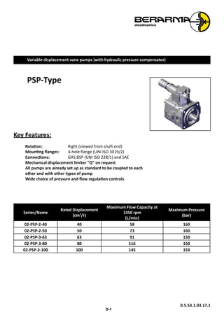
  • 1. D-1 Variable displacement vane pumps (with hydraulic pressure compensator) PSP-Type Key Features: Rotation: Right (viewed from shaft end) Mounting flanges: 4-hole flange (UNI ISO 3019/2) Connections: GAS BSP (UNI ISO 228/1) and SAE Mechanical displacement limiter "Q" on request All pumps are already set up as standard to be coupled to each other and with other types of pump Wide choice of pressure and flow regulation controls Series/Name Rated Displacement (cm3 /r) Maximum Flow Capacity at 1450 rpm (L/min) Maximum Pressure (bar) 02-PSP-2-40 40 58 160 02-PSP-2-50 50 73 160 02-PSP-3-63 63 91 150 02-PSP-3-80 80 116 150 02-PSP-3-100 100 145 150 0.5.53.1.03.17.1
  • 2. D-2 PSPCONTENTS CONTENTS GENERAL DESCRIPTION........................................................................................................................... D-3 CHARACTERISTICS................................................................................................................................... D-4 ORDERING CODE..................................................................................................................................... D-5 TECHNICAL DATA..................................................................................................................................... D-6 COMBINED PUMPS.................................................................................................................................. D-7 COMBINED PUMPS WITH SINGLE PRESSURE CONTROL DEVICE........................................................... D-10 PRESSURE-FLOW CONTROL SOLUTIONS................................................................................................ D-12 CHARACTERISTIC CURVES...................................................................................................................... D-15 OVERALL DIMENSIONS.......................................................................................................................... D-17 ACCESSORIES......................................................................................................................................... D-18 INSTRUCTIONS FOR INSTALLATION AND USE........................................................................................ D-20 WARNING All Berarma pumps have been carefully checked during manufacture and subjected to stringent testing cycles before shipment. To achieve optimum performance, avoid problems and maintain the warranty, the installation instructions enclosed with each pump sold must be strictly observed. NOTES Before selection and/or use of any Berarma product, it is important that the purchaser carefully analyses all aspects of its application and reviews the information in the current Berarma Technical-Sales catalogues. Due to the many different operating conditions and applications for Berarma products, the purchaser, through their own analysis and testing, is solely responsible for making the final selection of the products and assuring that all performance and safety requirements are met. Berarma S.r.l. accepts no responsibility for any editing mistakes in this catalogue. Berarma S.r.l. reserves the right to modify the products and data contained in this catalogue at any time and without prior notice.
  • 3. D-3 PSP GENERAL DESCRIPTION Berarma PSP variable displacement vane pumps come in two nominal sizes: Size 2-3. The PSP high pressure pumps (160 bar) are equipped with a HYDRAULIC pressure regulating device. Pump components include: a body (1), a drive rotor (2) which houses the vanes (3), vanes that transport the fluid into the inlet and outlet chambers; a stator (4) (mobile circular ring) for varying eccentricity and consequently displacement; side distribution plates with AXIAL HYDROSTATIC COMPENSATION (5) which delimit the inlet and outlet chambers; a guide block balancing adjustment screw (6) (absolutely must not be tampered with by the user); a displacement adjustment piston (7), a maximum flow regulation screw (8) (available on request); a pressure control device (9); and a pressure regulator (10). Hydraulic Symbol OUT IN 9 10 21 43 876 BA5 GENERALDESCRIPTION
  • 4. D-4 PSP CHARACTERISTICS • SILENT RUNNING from 63 to 72 dB(A) • HIGH EFFICIENCY • LONG WORKING LIFE • The pumps can be supplied with various proportional devices for flow, pressure and power control • ISO standard MOUNTING FLANGES • GAS (BSP), SAE standard PORT CONNECTIONS • MODULAR DESIGN: All Berarma pumps feature modular design for maximum flexibility and adaptability. The pumps comprise a body, common to each size, on which the various types of compensator devices (mechanical and hydraulic for pressure and flow control) can be mounted. The pump can therefore be converted from PVS to PSP and vice versa without any special modification, using the same standard pump body. PVSPSP IN CHARACTERISTICS
  • 5. D-5 PSP ORDERING CODE Series/ Name Size Displacement Flange Pressure setting Rotation Seals Controls Pressure Options 02 PSP H R Code Size Displacement (cm3 /r) 2 - 40 2 40 2 - 50 2 50 3 - 63 3 63 3 - 80 3 80 3 - 100 3 100 Code Flange Thread F UNI ISO3019/2 - 4 holes GAS UNI ISO 228/1; SAE Code Pressure setting H 30 - 160 bar (for Size 2) 30 - 150 bar (for Size 3) Code Rotation Direction R Right (viewed from shaft end) Code Seals M NBR E FPM (viton) Code Size / Omit for single stage pressure compensator PCS002 Pump with remote pressure control PCS003 Pump with two-stage pressure control, one with fixed setting PCS004 Pump with two-stage pressure control, both adjustable PCS005 Pump with proportional pressure control PCLS001 LOAD SENSING pump with single-stage pressure compensator PCLS002 LOAD SENSING pump with remote pressure control PCLS003 LOAD SENSING pump with two-stage pressure control, one with fixed setting PCLS004 LOAD SENSING pump with two adjustable pressure stages PCLS005 LOAD SENSING pump with proportional pressure control Code Options KL Key-Lock Compensator Q Displacement adjustment Ordering code example: • 02 PSP 2-40 F H R M • 02 PSP 3-80 F H R M Q PCS002 • 02 PSP 3-100 F H R M ORDERINGCODE
  • 6. D-6 PSP TECHNICAL DATA NOMINAL SIZE Size 2 Size 3 Geometric displacement according to UNI-ISO 3662 (cm3 /r) 40 - 50 63 - 80 - 100 Actual displacement (cm3 /r) 42.8 - 53.1 69 - 86.2 - 105.5 Maximum working pressure (bar) 160 150 Pressure setting range (bar) H: 30 - 160 H: 30 - 150 Permitted maximum drain port pressure (bar) 1 Inlet pressure (absolute - bar) 0.8 - 1.5 Speed range (r/min) 800 - 1800 Rotation direction (viewed from shaft end) Right (clockwise) R Loads on drive shaft NO RADIAL OR AXIAL LOADS ALLOWED Maximum torque on primary shaft (Nm) 400 740 Hydraulic fluid HM hydraulic oil according to ISO 6743/4; HLP hydraulic oil according to DIN 51524/2; organic ester HFD-U according to ISO 6743/4 (Quintolubric 888); for other fluids contact Berarma Technical-Sales Service Viscosity range (cSt, mm2/s) 22 - 68 Starting viscosity under full flow conditions (cSt, mm²/s) 400 max Viscosity index according to ISO 2909 100 min Inlet fluid temperature range (°C) -10 - +50 Maximum acceptable fluid contamination level 20/18/15 according to ISO 4406/99, CLASS 9 according to NAS 1638 Recommended fluid contamination level for a longer pump working life 18/16/13 according to ISO 4406/99, CLASS 7 according to NAS 1638 Weight (kg) 33 45 For different operating conditions, please contact Berarma Technical Service TECHNICALDATA
  • 7. D-7 PSP COMBINEDPUMPS COMBINED PUMPS BERARMA pumps are already set up for coupling to one another or to other types of pump (see table of possible combinations). The standard rotor shaft is set up for coupling (see pump section view, detail "A", on page 3). After removal of cover "B", the pump can be fitted with the different units already set up for coupling. With this solution BERARMA intends to avoid pumps with non-standard special applications, in order to simplify interchangeability and pump combination. For solutions different to the ones described, please contact Berarma Technical Service. 2 1 1) Combined Pumps 2) Non return valves - recommended installation (supplied on request) The ordering code should be specified according to the coupling sequence PRIMARY PUMP CODE + COUPLING UNIT CODE + SECONDARY PUMP CODE
  • 8. D-8 PSPCOMBINEDPUMPS Combined pumps should be mounted in decreasing order of absorbed power, paying attention to the maximum acceptable torques (see diagram below). The ordering code for a combined pump should be specified according to coupling sequence (primary pump code + coupling unit code + secondary pump code). • The sum of individual torques of all pumps in the complete pump combination must not exceed the maximum permissible torque value applicable to the primary pump shaft (Tmax see page 6). • Secondary pump torque (or sum of torques for more than one secondary pump) must not exceed the coupling unit maximum thru drive torque (Ta, see table below). PRIMARY PUMP SECONDARY PUMP COUPLING UNIT Pump type A Pump type C Code B Maximum thru drive torque Ta 02 PSP 2 (40-50) F 173 GEAR PUMP SIZE 1P (*) 3000022000 90 110 Nm GEAR PUMP SIZE 1 (*) 3000022100 90 GEAR PUMP SIZE 2 (*) 3000022200 90 GEAR PUMP SIZE 3 (*) 3000022300 90 01 PLP 05 16 F 107 3000020400 85 01 PLP 05 16 FGR2 107 3000022200 90 01 PHP 05 16 F 145 3000020400 85 01 PHP 05 16 FGR2 145 3000022200 90 01 PLP 1 (20-25-32) F 166 3000020100 87 01 PHP 1 (20-25-32)F 166 3000020100 87 02 PVS 2 (40-50) F 220 3000020200 102 02 PSP 2 (40-50) F 220 3000020200 102 SAE "A" (*) 3100000200 100.5 SAE "B" (*) 3100000300 126.5 02 PSP 3 (63-80-100) F 198 GEAR PUMP SIZE 1P (*) 3000022000 90 GEAR PUMP SIZE 1 (*) 3000022100 90 GEAR PUMP SIZE 2 (*) 3000022200 90 GEAR PUMP SIZE 3 (*) 3000022300 90 01 PLP 05 16 F 107 3000020400 85 01 PLP 05 16 FGR2 107 3000022200 90 01 PHP 05 16 F 145 3000020400 85 01 PHP 05 16 FGR2 145 3000022200 90 01 PLP 1 (20-25-32) F 166 3000020100 87 01 PHP 1 (20-25-32)F 166 3000020100 87 02 PVS 2 (40-50) F 220 3000020200 102 02 PSP 2 (40-50) F 220 3000020200 102 SAE "A" (*) 3100000200 100.5 SAE "B" (*) 3100000300 126.5 02 PVS 3 (63-80-100) F 245 3000020300 117 180 Nm 02 PSP 3 (63-80-100) F 245 3000020300 117 (*) For the secondary pump SAE A flange dimensions please see page 9. In order to find out the secondary SAE flange pump axial dimension please see the manufacturer's catalogue. (**) For the secondary gear pump flange dimensions please see page 9. In order find out the secondary gear pump axial dimension please see the manufacturer's catalogue. For other coupling unit types, please contact Berarma Technical-Sales Service.
  • 9. D-9 PSP SAE FLANGE DIMENSIONS FOR BERARMA COUPLING KIT Secondary pump Secondary pump with SAE flange should conform to the dimensions below Ø D E Ø F G H L M Ø N min max SAE "A" Ø82.5 7 Ø19.05 32 59 21.1 4.8 106.4 11.1 SAE "B" Ø101.6 9.5 Ø22.2 41 71 25.1 6.375 146 14.3 25.5 4.8 GEAR PUMP FLANGE DIMENSIONS FOR BERARMA COUPLING KIT Secondary pump Secondary gear pumps should conform to the dimensions below D E F Ø G Ø H J K L M N P Ø R gear pump 1P 29 20 4 25.4 8 M7 52.4 26.2 71.9 2.4 5.3 7.5 gear pump 1 35 23.5 5.5 30 12 M10x1 56 24.5 73 3 7.9 6.5 gear pump 2 40 28 5 36.5 14.7 M12x1.5 71.5 32.5 96 4 (*) 9.7 8.5 gear pump 3 47 33 5 50.8 19 M14x1.5 98.5 43 128 4 12.2 11 COMBINEDPUMPS
  • 10. D-10 PSP COMBINED PUMPS WITH SINGLE PRESSURE CONTROL DEVICE In response to market demand, Berarma has widened its range of products to cater to the request for higher displacement pumps. In fact, rather than developing large displacement pumps as such, Berarma has obtained the same results by combining standard SIZE 3 pumps controlled by a single hydraulic device for pressure regulation. This solution: • reduces noise level • cuts down production costs OVERALL DIMENSIONS U CETOP 03 [UNI ISO 4401-03] 19 40.5 16.3 26.6 32.5 6 31 67 105105 133 12 155.5 Ø18 140 max. 58.7 58.7 30.2 315 35 30.2 185 43 120 123 185 Ø200 301 315 10 105 77.8 77.8 Ø40 315 560 46 68 3434 Ø160 G D F 1/4" Gas BØ32 M10 C3/4" Gas E Ø51 A M12 A - SAE flange inlet port. B - SAE flange outlet port. C - GAS (BSP) thread drain ports. D - Pressure regulating knob. Rotate clockwise to increase pressure. E - Set-up for pressure control system with CETOP 03 [UNI ISO 4401-03] mounting surface. F - 1/4" GAS (BSP) port connection for pressure gauge. G - Identification plate. U - Manifold block, with CETOP 03 [UNI ISO 4401-03] mounting surface, for solenoid operated directional control valve to vent air. COMBINEDPUMPSWITHSINGLEPRESSURECONTROLDEVICE
  • 11. D-11 PSP COMBINEDPUMPSWITHSINGLEPRESSURECONTROLDEVICE U V S F CETOP03[UNIISO4401-03] T P R For further information, please consult the leaflet "Installation and start-up instructions for PSPC-type variable displacement vane combined pumps with single pressure control device". Geometric displacement (cm3 /r) 126 143 160 180 200 Actual displacement (cm3 /r) 138 155.2 172.4 191.7 211 R - Combined pumps with single pressure control device. S - Outlet manifold with check valves and maximum pressure relief valve. Supplied on request. Installation recommended. F - 1/4" GAS (BSP) port connection for pressure gauge. U - Manifold block, with CETOP 03 [UNI ISO 4401-03] mounting surface, for solenoid operated directional control valve to vent air. V - Solenoid operated directional control valve to vent air. Supplied on request (specify coil type). Must be installed in case of starting under zero flow setting conditions. ORDERING CODE 1 2 3 4 5 6 7 8 9 10 SERIES NAME SIZE DISPLACEMENT FLANGE PRESS. SETTING ROTATION SEALS PRESS. CONTROLS OPTIONS E.G. 02 PSPC 3 200 F H R M PCS... KL 1 PUMP SERIES = 02 6 PRESSURE SETTING = H 30-120 bar 2 PUMP NAME = PSPC 7 ROTATION = R (Right-hand [clockwise] rotation viewed from shaft end) 3 PUMP SIZE = 3 8 SEALS = M (NBR) 4 DISPLACEMENT CM3 /R = 126, 143, 160, 180, 200 9 PRESSURE-FLOW CONTROL SOLUTIONS page 13 PCS002 PCS003 PCS004 PCS005 5 FLANGE AND PORT CONNECTIONS= F (Flange: UNI ISO 3019/2 Inlet-Outlet: flange SAE J518 Drain port: GAS BSP UNI ISO 228/1 thread) 10 OPTIONS = KL (Key lock compensator)
  • 12. D-12 PSPPRESSURE-FLOWCONTROLSOLUTIONS PRESSURE-FLOW CONTROL SOLUTIONS PSP pumps can be supplied with a wide range of electro-hydraulic devices for pressure and flow control. In addition to its various pressure regulating systems, Berarma has developed a LOAD-SENSING device for its pumps (see diagrams with characteristic curves). This solution make Berarma pumps suitable to be used in energy saving systems. LOAD - SENSING The LOAD-SENSING flow regulating system is relatively simple; the signal for the compensator is picked up from the pump pressure line after a restriction and before an actuator. The regulating system (restriction) may comprise: throttle, manual or proportional type, or quick/slow units. As the extent of the restriction (at a fixed pressure drop Δp=20 bar [*]) changes, pump displacement is automatically varied by the system regardless of pressure variations in the circuit. The LOAD-SENSING system enables the notable limitation of power dissipation and is particularly suitable for applications with considerable torque (or force) and speed variations. [*] Note: For different operating conditions, please contact Berarma Technical Service. 619 16.3 26.6 32.5 31 40.5 T P Mounting surface CETOP-03 [UNI ISO 4401- 03] on PCS and PCLS compensators
  • 13. D-13 PSP PRESSURE-FLOWCONTROLSOLUTIONS Diagrams and characteristic curves for pressure regulation 1 Pump with standard pressure compensator 2 Pump with pressure compensator with CETOP 03 [UNI ISO 4401-03] P CS002 P CS003 P CS004 3 Pump with pressure compensator for proportional regulation with CETOP 03 [UNI ISO 4401-03] P CS005 Pump with two-stage pressure control, one of which is fixed (at the minimum pressure setting of the pump) Code P CS003 2 A q p A - Solenoid valve supplied only on request (please specify coil type) Standard pump 1 p q Pump with two-stage pressure control, both adjustable Code P CS004 2B A q p A - Berarma pressure relief valve supplied factory-assembled and tested B - Solenoid valve supplied only on request (please specify coil type) Pump with remote pressure control Code P CS002 2 A q p A - Maximum pressure relief valve (0-5 l/min) not supplied Note • The length of the pilot pipe between the compensator and the valve must not exceed 5 m • Remote control port 1/4" Gas (BSP) or 1/2"-20 UNF 2B Pump with proportional pressure control Code P CS005 3 A q p A - Pressure control proportional valve supplied only on request
  • 14. D-14 PSPPRESSURE-FLOWCONTROLSOLUTIONS Diagrams and characteristic curves for combined LOAD SENSING and pressure regulation 1 LOAD SENSING pump with standard pressure regulation P CLS001 2 LOAD SENSING pump with CETOP 03 mounting surface [UNI ISO 4401-03] P CLS002-3-4-5 3 Manual-electrical-proportional flow regulator not supplied Note • The length of the individual pipe between the flow regulator and the LOAD SENSING device must not exceed 5 m • Load Sensing signal connection 1/4" Gas LOAD SENSING pump with two-stage pressure control, one of which is fixed (at the minimum pressure setting of the pump) Code P CLS003 2 3 A q p A - Solenoid valve supplied only on request (please specify coil type) LOAD SENSING pump with standard pressure regulation Code P CLS001 1 3 q p LOAD SENSING pump with two adjustable pressure stages Code P CLS004 3 2 A B q p A - Berarma pressure relief valve supplied factory-assembled and tested B - Solenoid valve supplied only on request (please specify coil type) LOAD SENSING pump with remote pressure control Code P CLS002 3 2A q p A - Maximum pressure relief valve (0-5 l/min) not supplied Note • The length of the pilot pipe between the compensator and the valve must not exceed 5 m • Remote control port 1/4" Gas (BSP) LOAD SENSING pump with proportional pressure control Code P CLS005 3 2 A q p A - Pressure control proportional valve supplied only on request
  • 15. D-15 PSP CHARACTERISTICCURVES CHARACTERISTIC CURVES Indicative values related to 1450 r/min., HM hydraulic oil according to ISO 6743/4, ISO VG 32 according to ISO 3448, temperature 50°C 02 PSP 2 40-50 40 16 20 8 4 160140 12 1201008060 100 20 60 40 20 0 80 40 flow(l/min) pressure (bar) Volumetric efficiency -zero flow setting curve absorbedpower(kW) 1601208060 100 140 8 10 6 2 4 4020 0 40-50 drainage(l/min) pressure (bar) values established with zero flow setting 24 20 16 12 50 4 8 1601401201008060 100 60 40 80 20 20 0 40 flow(l/min) pressure (bar) Volumetric efficiency -zero flow setting curve absorbedpower(kW) Power consumption with maximum flow Power consumption with zero flow setting Noise level Maximum noise level measured on Berarma test bench with sound-level meter placed 1 metre from the pump, with flexible coupling 1601208060 100 140 74 76 4020 72 68 70 0 64 66 40-50 dB(A) pressure (bar) 50 ms 40-50 220 280 160 40 100 0 pressure(bar) time ms Response time and pressure peak Pressure peaks are due to the test system. Pressure peaks exceeding 30% of the maximum operating pressure must be eliminated by adopting the appropriate measures.
  • 16. D-16 PSPCHARACTERISTICCURVES Indicative values related to 1450 r/min., HM hydraulic oil according to ISO 6743/4, ISO VG 32 according to ISO 3448, temperature 50°C 02 PSP 3 63-80-100 28 63 200 120 80 160 7 14 150906030 40 0 120 21 flow(l/min) absorbedpower(kW) pressure (bar) volumetric efficiency -zero flow setting curve 15012060 90 12 10 8 6 2 4 30 0 63-80-100 drainage(l/min) pressure (bar) values established with zero flow setting 80 21 35 28 14 7 1509060 200 30 120 80 40 0 160 120 flow(l/min) pressure (bar) volumetric efficiency -zero flow setting curve absorbedpower(kW) Noise level Maximum noise level measured on Berarma test bench with sound-level meter placed 1 metre from the pump, with flexible coupling 15012060 90 74 76 30 72 68 70 0 64 66 63-80-100 dB(A) pressure (bar) 42 21 35 28 100 14 7 1509060 200 120 80 160 30 40 0 120 flow(l/min) pressure (bar) volumetric efficiency -zero flow setting curve absorbedpower(kW) Power consumption with maximum flow Power consumption with zero flow setting 50 ms 63-80-100 220 280 160 40 100 0 pressure(bar) time ms Response time and pressure peak Pressure peaks are due to the test system. Pressure peaks exceeding 30% of the maximum operating pressure must be eliminated by adopting the appropriate measures.
  • 17. D-17 PSP OVERALLDIMENSIONS OVERALL DIMENSIONS 02 PSP 2 40-50 (F) CETOP-03 [UNI ISO 4401-03] ** 26.2140 max. 30 52.4 Ø14 95 67 10 95 145.5 123 35.7 91 10 60 Ø160 114 11045max. 150 219 40 279 9 Ø125 70 Ø32 255.5 35 150 ØC D B E ØA Drain Port Outlet Port Inlet Port Mounting surface Pressure setting knob Flow regulation screw * *- Supplied on request (see page 15) ** - Supplied on request (dimensions: see page 12) Flange ØA B ØC D E F (ISO) 38 SAE (3000) 1"1/2 M12x45 25 SAE (3000) 1" M10x35 3/4" Gas (BSP) 02 PSP 3 63-80-100 (F) CETOP-03 [UNI ISO 4401-03] ** 58.7 30.2140 max. 35 Ø18 185 67 105105 43 155.5 275.5 12 133 10 77.8 68 Ø160 Ø40 43 105 Ø200 123 12045max. 185 245 313 469 ØC D E ØA B Drain Port Outlet Port Inlet Port Mounting surface Pressure setting knob Flow regulation screw * *- Supplied on request (see page 15) ** - Supplied on request (dimensions: see page 12) Flange ØA B ØC D E F (ISO) 51 SAE (3000) 2" M12x45 32 SAE (3000) 1"1/4 M10x40 3/4" Gas (BSP)
  • 18. D-18 PSPACCESSORIES ACCESSORIES KEY-LOCK PRESSURE COMPENSATOR DEVICE 9982 166 Note: In the case of combined pumpswithKey-Lockpressure compensator, please contact Berarma Technical Service. PRESSURE RELIEF VALVE FOR PSP PUMP (CODE 2010500600) 46 46 31 10 19 27.8 40.5 Ø5.5 16.3 6 32.5 26.6 10365 [UNI ISO 4401-03] CETOP-03 Mounting surface KEY-LOCK PRESSURE RELIEF VALVE FOR PSP PUMP (CODE 2010500700) CETOP-03 [UNI ISO 4401-03] 99 46 46 31 10 19 40.5 27.8 6 Ø5.5 26.6 32.5 16.3 10387 Mounting surface
  • 19. D-19 PSP ACCESSORIES FLOW-RATE REGULATOR UNIT 7 x 7 If the pump is supplied with flow-rate regulator unit "Q", set to less than 50% of the nominal flow, the pump can only start on condition that the system and pump are completely filled with fluid. Pump type 02PSP2-40 02PSP2-50 02PSP3-63 02PSP3-80 02PSP3-100 Indicative data that can change from pump to pump MAX flow at 1450 r/min (l/min) 62 78 100 125 152 MIN flow at 1450 r/min (l/min) 14.3 30.3 14 39 66 Reduced flow by screw turn (l/min) 23.8 23.8 34.5 34.5 34.5 FLANGES SAE J518 (3000 SERIES) SUPPLIED WITH SCREWS AND O-RING D E F C G ØB A H ØKJ Pump type Ordering code Nominal size A ØB C D E F G H J ØK Screws O-Ring 02 PVS PSP 2 5540000102 1" 1" Gas (BSP) 25 52.4 70 26.2 52 38 18 19 11 M10 OR 4131 NBR 5540000106 1" 1/2 1"½ Gas (BSP) 38 70 93 35.7 78 44 25 24 13.5 M12 OR 4187 NBR 02 PVS PSP 3 5540000104 1" 1/4 1"¼ Gas (BSP) 32 58.7 79 30.2 68 41 21 22 11.5 M10 OR 4150 NBR 5540000108 2" 2" Gas (BSP) 51 77.8 102 42.9 90 45 25 30 13.5 M12 OR 4225 NBR
  • 20. D-20 PSP INSTRUCTIONS FOR INSTALLATION AND USE 1) Sizes 2 and 3 PSP pumps must be mounted with the shaft along a horizontal axis and with the compensator device facing upward (see figure). When the pump is installed above the tank oil level, pay attention to the inlet pressure (see page 6). The minimum section of the inlet pipe must be equal to the section of the thread of the pump inlet port. The inlet pipes should be as short as possible, with a small number of bends and without internal section changes. 2) All return and drain pipes must be positioned so that the oil cannot be sucked back directly by the pump (see figure). The oil tank must be suitably sized in order to exchange the thermal power generated by the various system components and to provide a low recycle rate. To ensure the maximum pump working life, the inlet oil temperature must never be above 50°C. In systems where the pump runs for a long time under zero flow setting conditions, the installation of a heat exchanger in the drain line is recommended. The pressure on the drain port must never exceed the specified value (page 6). The drain pipe must always be independent from the other return lines, connected directly to the tank, and extended sufficiently inside the tank so as to be below the minimum oil level to avoid generating foam. Moreover, the drain pipe must be free of restrictions and as far as possible from the inlet pipe. 3) Motor-pump coupling must be made with a self-aligning flexible coupling with convex teeth and a polyamide cam. When assembling, maximum attention must be given to the distance between the half-couplings which must strictly fall within the values specified in the diagram below (detail "A"). Other types of motor-pump couplings are not permitted. No induced RADIAL or AXIAL LOADS are allowed on the pump shaft. 4) During initial installation, the pump must be run under maximum flow conditions (P connected to T), with the oil flowing directly into the tank, in order to induce air bleeding. For sizes 2 and 3 there is an air bleed on the compensator. This phase must run for several minutes. Pump priming (delivery of oil to the outlet) must occur within a few seconds, otherwise the pump must be turned off and the operation repeated. Subsequent start-ups under zero flow setting conditions are admissible only with pressure not exceeding 30 bar, and with the system and pump completely filled with oil. During the initial and subsequent starting operations, the difference between the oil temperature and the ambient temperature (body pump temperature) must not exceed 20°C. 4 - 7 45° 150 min. 50min. A A0.05 100min. IN OUT DRAIN 200min. 300 min. DETAIL A For further information, please consult the leaflet "Installation and start-up instructions for variable displacement vane combined pumps". INSTRUCTIONSFORINSTALLATIONANDUSE