
Recommended
Recommended
More Related Content
What's hot
What's hot (19)
Similar to 06 e-flightplanning
Similar to 06 e-flightplanning (20)
More from Rehmat Kaur
More from Rehmat Kaur (20)
Recently uploaded
Recently uploaded (20)
06 e-flightplanning
- 2. Aerotriangulation • Application of photogrammetry • strength is efficient coverage of lerger areas • thus blocks with many images required • larger blocks have thousands of images • Flight planning • given a region of interest to be surveyed • how should the images be taken in order to cover the region at the desired accuracy?
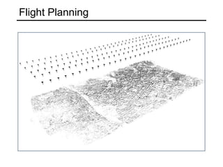
- 3. Aerotriangulation • Arrangement of images for aerial photogrammetry • restrictions due to flight path • regular raster of images (“image block”) • special cases (e.g. linear mapping of corridors) (flight) strip along-track overlapcross-track overlap baseline strip spacing
- 4. Aerotriangulation • Advantages • fewer control points → less terrestrial surveying effort • higher accuracy because of large number of tie points • higher reliability: complete redundancy exploited Efficiency • tie point measurement (without interpretation) cam be fully automated • significantly fewer ground control points needed (for modern GPS-supported blocks only 4-8) • Standard method • nowadays all photogrammetric projects are solved via aerotriangulation, other procedures are no longer in use
- 5. • How shall the flight be carried out to reach the specified accuracy? • large theoretical and practical studies • derived from those studies, simplified rules-of-thumb for planning • most important parameters - which camera positions? - which image scale? • Orientation is performed by joint least-squares adjustment of all images (“bundle adjustment”) • detailed treatment in Photogrammetrie 2 • here: rules-of-thumb without derivation • Goal is to develop a basic understanding for practical accuracies of photogrammetric surverying Projekt planning
- 6. Image blocks • Classical block setup • 60% along-track overlap • 20% cross-track overlap • 2-6 observations per point • “Modern” block setup • 80% along-track overlap • 60% cross-track overlap • (or even more) • 10-15 observations per point
- 7. Image blocks • Flight planning • the actual overlaps are usually larger than the nominally required ones, to have a safety margin for navigation uncertainty and varying terrain height • Large overlaps have become, or will soon become, the norm • in a fully digital and automated process no additional cost • Advantage: higher redundancy (DSM generation), lower distortions (orthophoto)
- 8. Ground control points • Classical setup • 60% along-track overlap • 20% cross-track overlap • Control point pattern • Full GCPs at block borders • Chains of height GCPs • in practice usually full GCPs (GPS) • exception: points with badly defined planimetric location XYZ control point Z control point tie point projection center
- 9. Ground control points • Classical setup • 60% along-track overlap • 20% cross-track overlap • Control point pattern • Full GCPs at block borders • Chains of height GCPs • in practice usually full GCPs (GPS) • exception: points with badly defined planimetric location ca. 3 km
- 10. Ground control points • Theoretical accuracies - planimetry • GCPs only required at block boundaries - point inside the block do not help • Distance between GCPs influences accuracy of estimated 3D points at the border (good: GCPs every 4-6 baselines) • Planimetric accuracy inside block very homogeneous, and decreases slowly with increasing block size • [Ackermann, 1966]
- 11. Ground control points • Theoretical accuracies - height • Classical setup: height GCPs in strip overlap (Toblerone-effect) • >60% cross-track overlap • no height GCPs inside block required • orientation between neighboring strips is stable (c.f. “classical” along-track overlap) 20% Q 60% Q
- 12. Ground control points • Theoretical accuracies - height • Classical setup: height GCPs in strip overlap (Toblerone-effect) • >60% cross-track overlap • no height GCPs inside block required • orientation between neighboring strips is stable (c.f. “classical” along-track overlap) 20% Q 60% Q
- 13. Ground control points • GPS/IMU Support • In GPS-supported aerotriangulation the projection centers become control points → accuracy independent of block size • GCPs only required at beginning and end of block - registration into to world coordinate system - checking the camera constant (height!) • GPS with cross-strips: 8 GCPs in block corners • >60% Querüberdeckung • 4 GCPs in block corners • Note: relation to world coordinate system has very little redundancy G PS 20% Q G PS 60% Q G PS 20% Q
- 14. Accuracy • Empirical formulas for project planning • with correct block geometry and GCP pattern the measurement accuracy is directly mapped to object space • Planimetric accuracy better than height • Influence of systematic errors and redundancy • Sclaing with image scale • Measurement accuracy of image points • M·σ ... measurement accuracy on the ground, e.g. • GSD = 15 cm, σ = ⅓ Pixel → M·σ = 5 cm σXY = 1.5 · M · σxy σZ = 2.0 · M · σxy M·σ σ
- 15. Measurement accuracy • Accuracy of observed image points • with correct GCP pattern and correct processung, the only influence factor is the image scale • Measurement accuracy depends on • definition uncertainty of points • image quality • lighting conditions • automatic/manual measurement • Empirical accuracy • for well-defined points 0.3-0.7 Pixel, depending on conditions • Note: often clients specify a maximal allowed inaccuracy, then calculate with 3σ ≈ 1.0-2.0 Pixel • relevant points oftne have high definition uncertainty (e.g. road boundary, tree, Strassenrand, Baum, gable roof, ...)