SlideShare a Scribd company logo
1 of 21
What is a network?
A computer network can be described as a system of interconnected devices that can
communicate using some common standard (called protocol). These devices
communicate to exchange resources (e.g. files and printers) and services.
Here is an example network consisting of two computers connected together:
In the example above, the two computers are directly connected using a cable. This
small network can be used to exchange data between just these two computers.
What if we want to expand our network? Then we can use a network device, either a
switch or a hub, to connect more than two computers together:
Now all of the devices on the network can communicate with each other.
We'll talk more about hubs and switches in just a moment. For now, just remember that
these devices serve as a central point to which all of the computers connect to.
OSI & TCP/IP models
OSI model
OSI (Open Systems Interconnection) model was created by the International
Organization for Standardization (ISO), an international standard-setting body. It was
designed to be a reference model for describing the functions of a communication
system. It has seven layers, with each layer describing a different function of data
traveling through a network.
Here is the graphical representation of these layers:
The layers are usually numbered from the last one, meaning that the Physical layer is
consider to be the first layer. It is good to learn these layers, since there will certainly be
a couple of questions on the CCNA exam regarding them. Most people learn the
mnemonic „Please Do Not Throw Sausage Pizza Away“:
So, what is the purpose of these layers?
They are most commonly used by vendors. They enable them to implement some
functionality into a networking device, which then enables easier interoperability with
devices from other vendors.
Here is a brief description of each of these layers.
Physical – defines how to move bits from one device to another. It details how cables,
connectors and network interface cards are going to work and how to send and receive
bits.
Data Link – encapsulates a packet in a frame. A frame contains a header and a trailer
that enable devices to communicate. A header, most commonly, contains a source and
a destination MAC address. A trailer contains the Frame Check Sequence field, which is
used to detect transmission errors.
The data link layer has two sublayers:
1. Logical Link Control – used for flow control and error detection
2. Media Access Control – used for hardware addressing and controlling the access
method
Network – defines device addressing, routing, and path determination. Device (logical)
addressing is used to identify a host on a network (e.g. by its IP address).
Transport – segments great chunks of data received from the upper layer protocols.
Establishes and terminates connections between two computers. Used for flow control
and data recovery.
Session – defines how to establish and terminate a session between the two systems.
Presentation – defines data formats. Compression and encryption are defined at this
layer.
Application – this layer is the closest to the user. It enables network applications to
communicate with other network applications.
The following table shows which protocols reside on which layer:
TCP/IPmodel
The TCP/IP model was created in the 1970s by the Defense Advance Research Project
Agency (DARPA). Like the OSI model, it describes general guidelines for designing and
implementing computer protocols.
It consists of four layers: Network Access, Internet, Transport, and Application.
The following picture show the comparison between the TCP/IP model and OSI model:
As you can see, the TCP/IP model has fewer layers than the OSI model. The
Application, Presentation, and Session layers of the OSI model are merged in only one
layer, Application layer, in the TCP/IP model. Also, Physical and Data Link layers are
called Network Access layer in the TCP/IP model.
Differences between OSI and TCP/IP model
There are some other differences between these two models, besides the obvious
difference in the number of layers. OSI model prescribes the steps needed to transfer
data over a network and it is very specific in it, defining which protocol is used at each
layer and how. The TCP/IP model is not that specific. It can be said that the OSI model
prescribes and TCP/IP model describes.
Encapsulation
The term "encapsulation" is used to describe a process of adding headers and trailers
around some data. For example, when you send an email using your favourite email
program (like Outlook or Thunderbird) that email is sent from the Application layer to the
Transport layer. The Transport layer encapsulates the data and adds its own header
(with its own information, such as which port will be used) and passes the data to the
Internet layer, which again encapsulates the received data and adds its own header,
usually with information about the source and destination IP addresses. The Internet
layer than passes the data to the Network Access layer. This layer is the only layer that
adds both a header and a trailer. The data is then sent through a physical network link.
Each layer adds its own information:
The term "decapsulation" refers to the process of removing headers and trailers as data
passes from lower to upper layers. This process happens on a computer that is
receiving data.
Frame, packet, segment
Frame - the term "frame" refers to the encapsulated data defined by the Network
Access layer. A frame can have a header and a trailer that encapsulate a data section.
Packet - the term "packet" is used to describe the encapsulated data defined by the
Internet layer. A packet can have a header with the source and destination IP
addresses.
Segment - the term "segment" describes encapsulated data defined by the Transport
layer. A segment can have a header with informations such as source and destionation
port numbers, sequence and acknowledgment numbers, etc.
Ethernet
Ethernet is the most used networking technology for LANs today. It defines wiring and
signaling for the Physical layer of the OSI model. For the Data Link layer, it defines
frame formats and protocols.
Ethernet is described as IEEE 802.3 standard. It uses Carrier Sense Multiple Access
with Collision Detection (CSMA/CD) access method and supports speeds up to 100
Gbps. It can use coaxial, twisted pair and fiber optic cables. Ethernet uses frames to
with source and destination MAC addresses to deliver data.
MAC & IP addresses
MAC address
A Media Access Control (MAC) address is a 48-bit address that is used for
communication between two hosts in an Ethernet environment. It is a hardware
address, which means that it is stored in the firmware of the network card.
A MAC address is supposed to be globaly unique. Each network card vendor gets its
share of addresses (represented by the first 24 bits).
The address is written in the form of 12 hexadecimal digits. For example, consider the
following MAC address:
D8-D3-85-EB-12-E3
Every hexadecimal character represents 4 bits, so the first six hexadecimal characters
represent the vendor (in this case, Hewlett Packard).
Howto find outyourownMAC address?
If you are using Windows, enter the Command Prompt (Start - Programs - Accessories -
Command Prompt). Type the ipconfig/all command and you should see a field called
Physical address under the Ethernet adapter settings:
If you are using Linux, type the ifconfig command. You should see your MAC address
referred to as HWaddress.
IP address
An IP address is a 32-bit number that identifies a host on a network. It is usually written
in the form of four decimal numbers seperated by periods (e.g. 10.0.50.1).
In contrast to MAC address, an IP address is a logical address. Any device that wants
to communicate with other device using TCP/IP needs to have an IP address. It can be
configured manually or it can be obtained from a DHCP server.
The term "IP address" is usually used for IPv4, which is the fourth version of the IP
protocol. A newer version exists, IPv6, and uses 128-bit addressing.
Private IP addresses
There are three ranges of addresses that can be used in a private network (e.g. your
home LAN). These addresses are not routable through the Internet.
Private addresses ranges:
10.0.0.0 – 10.255.255.255
172.16.0.0 – 172.31.255.255
192.168.0.0 – 192.168.255.255
How to find out your IP address
Windows users:
Enter the Command Promt (Start - Programs - Accessories - Command Prompt).
Enter ipconfig. You should see a field called IP address.
Linux users:
Enter ifconfig. You should see a field called inet addr:
Network devices
Hubs
A hub serves as a central point to which all of the hosts in a network connect to. It is an
OSI layer 1 device. It receives a signal from one port and sends it out to all other ports.
Sometimes it is called a multiport repeater (photo credit: Wikipedia)
Today, these devices are considered obsolete and switches are commonly used
instead. Hubs have numerous disadvantages. They are not aware of the traffic that
passes through them. They create only one large collision domain. A hub typically
operates in half duplex. There is also a security issue with hubs since the traffic is
forwarded to all ports (except the source port), which makes it possible to capture all
traffic on a network with a network sniffer!
Switches
Like hubs, a switch is used to connect multiple hosts together, but it has many
advantages over a hub. Switch is an OSI Layer 2 device, which means that it can
inspect received traffic and make forwarding decisions. Each port on a switch is a
separate collision domain and can run in a full duplex mode (photo credit: Wikipedia).
How switches work
Let's take a look at the following example:
Host A is trying to communicate with Host B and sends a packet. A packet arrives at the
switch, which looks at the destination MAC address. The switch then searches that
address in its MAC address table. If the MAC address is found, the switch then forwards
the packet only to the port that connected to the frame's destination. If the MAC address
is not found, the switch will flood the frame out all other ports. To learn which MAC
address is associated with which port, switches examine the source MAC addresses of
the receiving packet and store that MAC addresses in their MAC address table.
What is a MAC address table?
A MAC address table lists which MAC address is connected to which port. It is used by
switches to make forwarding decisions. The table is populated by examining the source
MAC address of the incoming packet. If the source MAC address of a packet is not
present in the table, the switch adds an entry to it's MAC address table.
The picture below show how a MAC address table on a switch looks like:
Difference between a switch and a bridge
A switch is sometimes called a multiport bridge, but there are differences between these
two devices. A bridge usually has fewer ports than switch. A switch operates faster
because it is hardware-based, which means that it uses chips (ASICs) when making
forwarding decisions. In contrast, a bridge is software based. A switch can also have
multiple spanning-tree instances while a bridge can have only one. Switches can also
have multiple broadcast domains, one per VLAN.
Routers
A router is a device that routes packets from one network to another. A router is most
commonly an OSI Layer 3 device. Routers divide broadcast domains and have traffic
filtering capabilities.
The picture below shows a typical home router:
How routers work
A router uses IP addresses to figure out where to send packets. If two hosts from
different networks want to communicate, they will need a router between them to route
packets
For example, check the following scenario:
Host A and host B are on different networks. If host A wants to communicate with host
B, it will have to send a packet to the router. The router receives the packet and checks
the destination IP address. If the destination IP address is in the routing table, the router
will forward the packet out the interface associated with that network.
What is a routing table?
A routing table lists a route for every network that a router can reach. It can be statically
configured (using IOS commands) or dynamically learned (using a routing protocol). It is
used by routers when deciding where to forward packets.
The picture below shows how a routing table looks like:
The command to display an IP routing table is show ip route. In the picture above, you
can see that this router has two directly connected subnets. Let's take a closer look at
the first entry in the routing table:
„C“ means that the route is a directly connected route. The network in question is
10.0.0.0/8, and the router will forward each packet destined for that network out
interface FastEthernet0/1.
NOTE – in Windows, you can use the netstat –r command to display the routing table
of your system.
Types of Ethernet cabling
There are three cable types commonly used for Ethernet cabling: coaxial, twisted pair,
and fiber-optic cabling. In today's LANs, the twisted pair cabling is the most popular type
of cabling, but the fiber-optic cabling usage is increasing, especially in high performance
networks. Coaxial cabling is generally used for cable Internet access. We will explain all
three types of cabling. We will also explain a difference between a straight-through and
crossover cable.
Coaxialcabling
Coaxial cable has an inner conductor that runs down the middle of the cable. The
conductor is surrounded by a layer of insulation which is then surrounded by another
conducting shield, which makes this type of cabling resistant to the outside interference.
This type of cabling comes in two types, thinnet and thicknet. Both types have a
maximum transmission speed of 10 Mbps. Coaxial cabling was used for computer
networks, but today are largely replaced by twisted-pair cabling (Photo credit:
Wikipedia)
Twisted-pair cabling
A twisted-pair cable has four pair of wires. These wires are twisted around each other to
reduce crosstalk and outside interference. This type of cabling is common in most
current LANs.
Twisted-pair cabling can be used for telephone and network cabling. It comes in two
versions, UTP (Unshielded Twisted-Pair) and STP (Shielded Twisted-Pair). The
difference between these two is that an STP cable has an additional layer of insulation
that protects data from outside interferences.
Here you can see how a twisted pair cable looks like (Photo credit: Wikipedia):
A twisted-pair cable uses 8P8C connector, sometimes wrongly referred to as RJ45
connector (Photo credit: Wikipedia).
Fiber-optic cabling
This type of cabling uses optical fibers to transmit data in the form of light signals. The
cables have strands of glass surrounded by a cladding material (Photo credit:
Wikipedia).
This type of cabling can support greater cable lengths than any other cabling type (up to
a couple of miles). The cables are also immune to electromagnetic interference. As you
can see, this cabling method has many advantages over other methods but it's
drawback is that it is the most expensive type of cabling.
There are two types of fiber-optic cables:
• Single-mode fiber (SMF) - uses only a single ray of light to carry data
• Multi-mode fiber (MMF) - uses multiple rays of light to carry data
Two types of connectors are commonly used:
• ST (Straight-tip connector)
• SC (Subscriber connector)
Types of Ethernet cables
Ethernet cables can come in two forms:
Straight-through cable - it has identical wiring on both ends (pin 1 on one end of the
cable is connected to pin 1 at the other end of the cable, pin 2 is connected to pin 2
etc.). This type of cable is used to connect:
• computer to hub
• computer to switch
• router to hub
• router to switch
Computers and routers use wires 1 and 2 to transmit data and wires 3 and 6 to receive
data. Hubs and switches use wires 1 and 2 to receive data and wires 3 and 6 to send
data. That is why, if you want to connect two computers together, you will need a
crossover cable.
Crossover cable – wire pairs are swapped, which means that different pins are
connected together - pin 1 on one end of the cable is connected to pin 3 on the other
end, pin 2 on one end is connected to pin 6 on the other end (Photo credit: Wikipedia).
This type of cable is used when you need to connect two devices that use the same
wires to send and the same wires to receive data. For example, consider connecting
two computers together. If you use straight-through cable, with identical wiring in both
ends, both computers will use wires 1 and 2 to send data. If computer A sends some
packets to computer B, computer A will send that data using wires 1 and 2. That will
cause a problem because computers expect packets to be received on wires 3 and 6,
and your network will not work properly
Wide area network
The term „wide area network“ is used to describe a network that spans multiple
geographic locations. Consider an example. A company has two offices, one in London
and one in Berlin. Both offices have a LAN. If the company connects these two LANs
together using WAN technology, a WAN is created.
The key difference between LANs and WANs is that the company usually doesn't own
WAN infrastructure. A company usually leases WAN services from a service provider.
Frame Relay, ATM and X.25 are different types of WAN technologies. The Internet can
also be considered a WAN
Local area network & Metropolitan area
network
Localarea network(LAN)
The term "local area network" is commonly used to describe a network of devices in a
limited area (a house, office, building...). This type of network is usually capable of
achieving high data transfer rate (up to 10 Gbps!) at low cost.
Some of the most popular LAN technologies are Ethernet, Token Ring and FDDI. Most
LAN networks use TCP/IP to communicate. Twisted-pair cabling is usually used in a
LAN.
Examples of this type of network are a small office network inside a single building or
your home network.
Metropolitan area network(MAN)
The term „metropolitan area network“ is used to describe a network in a single
metropolitan area, hence the name. This type of network is usually bigger than a LAN
and smaller than a WAN. An example of this type of network would be a network that
connects two company offices inside the same city.
Classes of IP addresses
TCP/IP defines five classes of IP addresses: class A, B, C, D, and E. Each class has a
range of valid IP addresses. The value of the first octet determines the class. IP
addresses from the first three classes (A, B and C) can be used for host addresses. The
other two classes are used for other purposes (class D for multicast and class E for
experimental purposes).
Classes of IP addresses:
Special IP address ranges:
0.0.0.0/8 - addresses used to communicate with the current network
127.0.0.0/8 - loopback addresses
169.254.0.0/16 - link-local addresses (APIPA)
Subnet mask
An IP address is divided into two parts: network and host parts. For example, an IP
class A address consists of 8 bits identifying the network and 24 bits identifying the
host. This is because the default subnet mask for a class A IP address is 8 bits long.
(or, written in dotted decimal notation, 255.0.0.0). What does it mean? Well, like an IP
address, a subnet mask also consists of 32 bits. Computers use it to determine the
network part and the host part of an address. The 1s in the subnet mask represent a
network part, the 0s a host part.
Computers works only with bits. The math used to determine a network range is binary
AND.
Let's say that we have the IP address of 10.0.0.1 with the default subnet mask of 8 bits
(255.0.0.0).
First, we need to convert the IP address to binary:
IP address: 10.0.0.1 = 00001010.00000000.00000000.00000001
Subnet mask 255.0.0.0 = 11111111.00000000.00000000.0000000
Computers then use the AND operation to determine the network number:
The computer can then determine the size of the network. Only IP addresses that
begins with 10 will be in the same network. So, in this case, the range of addresses in
this network is 10.0.0.0 – 10.255.255.255.
NOTE - A subnet mask must always be a series of 1s followed by a series of 0s.
Traceroute
Traceroute is a CLI (Command-line interface)-based tool used to identify the path used
by a packet to reach its target. This tool also uses ICMP messages, but unlike ping,
identifies every router in a path. Traceroute is useful when troubleshooting network
problems because it can help identify where exactly the problem is.
Traceroute sends a series of ICMP echo request packets to a destination. First series of
messages has a Time to Live (TTL) parameter set to 1, which means that the first router
in a path will discard the packet and send an ICMP Time Exceeded message. TTL is
then increased by one until the destination host is reached and an ICMP echo reply
message is received. Originating host can then use received ICMP messages to identify
all routers in a path.
The traceroute command on Windows is named tracert. On Unix and Cisco IOS
traceroute it is invoked using the traceroute command.
Here is an example showing the tracert command in Windows:
Traceroute on Unix-like operating systems
Traceroute command on Unix works slighty different than the Windows version. It uses
UDP packets with a large destination port number (33434 to 33534) that is unlikely to be
used by any application at the destination host. Like the Windows version of the
command, traceroute on Unix uses TTL to get the IP addresses of the intermediary
routers. When a destination host is reached, it replies with an ICMP port unreachable
message.

More Related Content

What's hot

OSI Reference Model and TCP/IP (Lecture #3 ET3003 Sem1 2014/2015)
OSI Reference Model and TCP/IP (Lecture #3 ET3003 Sem1 2014/2015)OSI Reference Model and TCP/IP (Lecture #3 ET3003 Sem1 2014/2015)
OSI Reference Model and TCP/IP (Lecture #3 ET3003 Sem1 2014/2015)Tutun Juhana
 
OSI model and TCP/IP model
OSI model and TCP/IP modelOSI model and TCP/IP model
OSI model and TCP/IP modelRubal Sagwal
 
Network protocols
Network protocolsNetwork protocols
Network protocolsHemnath R.
 
Networking Basics
Networking BasicsNetworking Basics
Networking BasicsCarlo Fonda
 
Networking Standards And Protocols
Networking Standards And ProtocolsNetworking Standards And Protocols
Networking Standards And ProtocolsSteven Cahill
 
Basic ip and networking ver 3 kl
Basic ip and networking ver 3 klBasic ip and networking ver 3 kl
Basic ip and networking ver 3 klAzhar Ali
 
Report of TCP/IP
Report of TCP/IPReport of TCP/IP
Report of TCP/IPMannu Khani
 
Lecture 2 -_understanding_networks_with_presenter_notes
Lecture 2 -_understanding_networks_with_presenter_notesLecture 2 -_understanding_networks_with_presenter_notes
Lecture 2 -_understanding_networks_with_presenter_notesSerious_SamSoul
 
Osi reference model and the tcp
Osi reference model and the tcpOsi reference model and the tcp
Osi reference model and the tcpAgrippa Mungazi
 
Internetworking
InternetworkingInternetworking
InternetworkingRaghu nath
 
Advanced computer network lab manual (practicals in Cisco Packet tracer)
Advanced computer network lab manual (practicals in Cisco Packet tracer)Advanced computer network lab manual (practicals in Cisco Packet tracer)
Advanced computer network lab manual (practicals in Cisco Packet tracer)VrundaBhavsar
 
Slides for protocol layering and network applications
Slides for protocol layering and network applicationsSlides for protocol layering and network applications
Slides for protocol layering and network applicationsjajinekkanti
 
OSI model (7 LAYER )
OSI model (7 LAYER )OSI model (7 LAYER )
OSI model (7 LAYER )AAKASH S
 
Protocol
ProtocolProtocol
ProtocolShi Na
 
Internet Protocols
Internet ProtocolsInternet Protocols
Internet ProtocolsMohamed Daif
 
53426980 tcp-ip
53426980 tcp-ip53426980 tcp-ip
53426980 tcp-ipSharan Huggi
 
Introduction to the OSI 7 layer model and Data Link Layer
Introduction to the OSI 7 layer model and Data Link LayerIntroduction to the OSI 7 layer model and Data Link Layer
Introduction to the OSI 7 layer model and Data Link LayerVNIT-ACM Student Chapter
 

What's hot (20)

OSI Reference Model and TCP/IP (Lecture #3 ET3003 Sem1 2014/2015)
OSI Reference Model and TCP/IP (Lecture #3 ET3003 Sem1 2014/2015)OSI Reference Model and TCP/IP (Lecture #3 ET3003 Sem1 2014/2015)
OSI Reference Model and TCP/IP (Lecture #3 ET3003 Sem1 2014/2015)
 
OSI model and TCP/IP model
OSI model and TCP/IP modelOSI model and TCP/IP model
OSI model and TCP/IP model
 
Network protocols
Network protocolsNetwork protocols
Network protocols
 
Networking Basics
Networking BasicsNetworking Basics
Networking Basics
 
Internetworking
InternetworkingInternetworking
Internetworking
 
Networking Standards And Protocols
Networking Standards And ProtocolsNetworking Standards And Protocols
Networking Standards And Protocols
 
Basic ip and networking ver 3 kl
Basic ip and networking ver 3 klBasic ip and networking ver 3 kl
Basic ip and networking ver 3 kl
 
Report of TCP/IP
Report of TCP/IPReport of TCP/IP
Report of TCP/IP
 
Lecture 2 -_understanding_networks_with_presenter_notes
Lecture 2 -_understanding_networks_with_presenter_notesLecture 2 -_understanding_networks_with_presenter_notes
Lecture 2 -_understanding_networks_with_presenter_notes
 
Osi reference model and the tcp
Osi reference model and the tcpOsi reference model and the tcp
Osi reference model and the tcp
 
Internetworking
InternetworkingInternetworking
Internetworking
 
computer network OSI layer
computer network OSI layercomputer network OSI layer
computer network OSI layer
 
Advanced computer network lab manual (practicals in Cisco Packet tracer)
Advanced computer network lab manual (practicals in Cisco Packet tracer)Advanced computer network lab manual (practicals in Cisco Packet tracer)
Advanced computer network lab manual (practicals in Cisco Packet tracer)
 
Internet Protocols
Internet ProtocolsInternet Protocols
Internet Protocols
 
Slides for protocol layering and network applications
Slides for protocol layering and network applicationsSlides for protocol layering and network applications
Slides for protocol layering and network applications
 
OSI model (7 LAYER )
OSI model (7 LAYER )OSI model (7 LAYER )
OSI model (7 LAYER )
 
Protocol
ProtocolProtocol
Protocol
 
Internet Protocols
Internet ProtocolsInternet Protocols
Internet Protocols
 
53426980 tcp-ip
53426980 tcp-ip53426980 tcp-ip
53426980 tcp-ip
 
Introduction to the OSI 7 layer model and Data Link Layer
Introduction to the OSI 7 layer model and Data Link LayerIntroduction to the OSI 7 layer model and Data Link Layer
Introduction to the OSI 7 layer model and Data Link Layer
 

Similar to Cisco doc

Network essentials chapter 3
Network essentials  chapter 3Network essentials  chapter 3
Network essentials chapter 3Raghu nath
 
IMD 251 - Networking
IMD 251 - NetworkingIMD 251 - Networking
IMD 251 - Networkingisma ishak
 
Internet basics and Cloud Computing- Manish Jha
Internet basics and Cloud Computing- Manish JhaInternet basics and Cloud Computing- Manish Jha
Internet basics and Cloud Computing- Manish Jhamanish jha
 
Manish Jha- Research Scholar- Internet Basics Requriement
Manish Jha- Research Scholar- Internet Basics RequriementManish Jha- Research Scholar- Internet Basics Requriement
Manish Jha- Research Scholar- Internet Basics RequriementManish Jha
 
layering.pdf
layering.pdflayering.pdf
layering.pdfBoostHub
 
Introduction to networking
Introduction to networkingIntroduction to networking
Introduction to networkingMohsen Sarakbi
 
Network essentials chapter 2
Network essentials  chapter 2Network essentials  chapter 2
Network essentials chapter 2Raghu nath
 
Concept of networking
Concept of networkingConcept of networking
Concept of networkingsumit dimri
 
pppppppppppppppppjjjjjjjjjjjpppppppp.pptx
pppppppppppppppppjjjjjjjjjjjpppppppp.pptxpppppppppppppppppjjjjjjjjjjjpppppppp.pptx
pppppppppppppppppjjjjjjjjjjjpppppppp.pptxzeyadosama505
 
Dist 03-4
Dist 03-4Dist 03-4
Dist 03-4jesuscried
 
Automation Networking By Shivam Singh
Automation Networking By Shivam SinghAutomation Networking By Shivam Singh
Automation Networking By Shivam SinghShivam Singh
 
Class_notes_InternetTechnology
Class_notes_InternetTechnologyClass_notes_InternetTechnology
Class_notes_InternetTechnologyGulrez Khan
 
computer network and chapter 7 OSI layers.pptx
computer network and chapter 7 OSI layers.pptxcomputer network and chapter 7 OSI layers.pptx
computer network and chapter 7 OSI layers.pptxgadisaAdamu
 
chapter 4.pptx
chapter 4.pptxchapter 4.pptx
chapter 4.pptxshucaybcabdi
 
The Solaris Network Environment (Presentation
The Solaris Network Environment (PresentationThe Solaris Network Environment (Presentation
The Solaris Network Environment (Presentationmayur6789
 

Similar to Cisco doc (20)

Network essentials chapter 3
Network essentials  chapter 3Network essentials  chapter 3
Network essentials chapter 3
 
IMD 251 - Networking
IMD 251 - NetworkingIMD 251 - Networking
IMD 251 - Networking
 
Internet basics and Cloud Computing- Manish Jha
Internet basics and Cloud Computing- Manish JhaInternet basics and Cloud Computing- Manish Jha
Internet basics and Cloud Computing- Manish Jha
 
Manish Jha- Research Scholar- Internet Basics Requriement
Manish Jha- Research Scholar- Internet Basics RequriementManish Jha- Research Scholar- Internet Basics Requriement
Manish Jha- Research Scholar- Internet Basics Requriement
 
Osi model
Osi modelOsi model
Osi model
 
layering.pdf
layering.pdflayering.pdf
layering.pdf
 
Introduction to networking
Introduction to networkingIntroduction to networking
Introduction to networking
 
Network essentials chapter 2
Network essentials  chapter 2Network essentials  chapter 2
Network essentials chapter 2
 
OSI model.pptx
OSI model.pptxOSI model.pptx
OSI model.pptx
 
Concept of networking
Concept of networkingConcept of networking
Concept of networking
 
pppppppppppppppppjjjjjjjjjjjpppppppp.pptx
pppppppppppppppppjjjjjjjjjjjpppppppp.pptxpppppppppppppppppjjjjjjjjjjjpppppppp.pptx
pppppppppppppppppjjjjjjjjjjjpppppppp.pptx
 
Dist 03-4
Dist 03-4Dist 03-4
Dist 03-4
 
Automation Networking By Shivam Singh
Automation Networking By Shivam SinghAutomation Networking By Shivam Singh
Automation Networking By Shivam Singh
 
Class_notes_InternetTechnology
Class_notes_InternetTechnologyClass_notes_InternetTechnology
Class_notes_InternetTechnology
 
computer network and chapter 7 OSI layers.pptx
computer network and chapter 7 OSI layers.pptxcomputer network and chapter 7 OSI layers.pptx
computer network and chapter 7 OSI layers.pptx
 
chapter 4.pptx
chapter 4.pptxchapter 4.pptx
chapter 4.pptx
 
Computer networking
Computer networkingComputer networking
Computer networking
 
Computer networking
Computer networkingComputer networking
Computer networking
 
The Solaris Network Environment (Presentation
The Solaris Network Environment (PresentationThe Solaris Network Environment (Presentation
The Solaris Network Environment (Presentation
 
Internet1
Internet1Internet1
Internet1
 

Recently uploaded

call girls in Kamla Market (DELHI) 🔝 >༒9953330565🔝 genuine Escort Service 🔝✔️✔️
call girls in Kamla Market (DELHI) 🔝 >༒9953330565🔝 genuine Escort Service 🔝✔️✔️call girls in Kamla Market (DELHI) 🔝 >༒9953330565🔝 genuine Escort Service 🔝✔️✔️
call girls in Kamla Market (DELHI) 🔝 >༒9953330565🔝 genuine Escort Service 🔝✔️✔️9953056974 Low Rate Call Girls In Saket, Delhi NCR
 
Crayon Activity Handout For the Crayon A
Crayon Activity Handout For the Crayon ACrayon Activity Handout For the Crayon A
Crayon Activity Handout For the Crayon AUnboundStockton
 
How to Make a Pirate ship Primary Education.pptx
How to Make a Pirate ship Primary Education.pptxHow to Make a Pirate ship Primary Education.pptx
How to Make a Pirate ship Primary Education.pptxmanuelaromero2013
 
MICROBIOLOGY biochemical test detailed.pptx
MICROBIOLOGY biochemical test detailed.pptxMICROBIOLOGY biochemical test detailed.pptx
MICROBIOLOGY biochemical test detailed.pptxabhijeetpadhi001
 
Final demo Grade 9 for demo Plan dessert.pptx
Final demo Grade 9 for demo Plan dessert.pptxFinal demo Grade 9 for demo Plan dessert.pptx
Final demo Grade 9 for demo Plan dessert.pptxAvyJaneVismanos
 
Introduction to ArtificiaI Intelligence in Higher Education
Introduction to ArtificiaI Intelligence in Higher EducationIntroduction to ArtificiaI Intelligence in Higher Education
Introduction to ArtificiaI Intelligence in Higher Educationpboyjonauth
 
Computed Fields and api Depends in the Odoo 17
Computed Fields and api Depends in the Odoo 17Computed Fields and api Depends in the Odoo 17
Computed Fields and api Depends in the Odoo 17Celine George
 
Presiding Officer Training module 2024 lok sabha elections
Presiding Officer Training module 2024 lok sabha electionsPresiding Officer Training module 2024 lok sabha elections
Presiding Officer Training module 2024 lok sabha electionsanshu789521
 
How to Configure Email Server in Odoo 17
How to Configure Email Server in Odoo 17How to Configure Email Server in Odoo 17
How to Configure Email Server in Odoo 17Celine George
 
Gas measurement O2,Co2,& ph) 04/2024.pptx
Gas measurement O2,Co2,& ph) 04/2024.pptxGas measurement O2,Co2,& ph) 04/2024.pptx
Gas measurement O2,Co2,& ph) 04/2024.pptxDr.Ibrahim Hassaan
 
POINT- BIOCHEMISTRY SEM 2 ENZYMES UNIT 5.pptx
POINT- BIOCHEMISTRY SEM 2 ENZYMES UNIT 5.pptxPOINT- BIOCHEMISTRY SEM 2 ENZYMES UNIT 5.pptx
POINT- BIOCHEMISTRY SEM 2 ENZYMES UNIT 5.pptxSayali Powar
 
Earth Day Presentation wow hello nice great
Earth Day Presentation wow hello nice greatEarth Day Presentation wow hello nice great
Earth Day Presentation wow hello nice greatYousafMalik24
 
18-04-UA_REPORT_MEDIALITERAСY_INDEX-DM_23-1-final-eng.pdf
18-04-UA_REPORT_MEDIALITERAСY_INDEX-DM_23-1-final-eng.pdf18-04-UA_REPORT_MEDIALITERAСY_INDEX-DM_23-1-final-eng.pdf
18-04-UA_REPORT_MEDIALITERAСY_INDEX-DM_23-1-final-eng.pdfssuser54595a
 
Painted Grey Ware.pptx, PGW Culture of India
Painted Grey Ware.pptx, PGW Culture of IndiaPainted Grey Ware.pptx, PGW Culture of India
Painted Grey Ware.pptx, PGW Culture of IndiaVirag Sontakke
 
ECONOMIC CONTEXT - PAPER 1 Q3: NEWSPAPERS.pptx
ECONOMIC CONTEXT - PAPER 1 Q3: NEWSPAPERS.pptxECONOMIC CONTEXT - PAPER 1 Q3: NEWSPAPERS.pptx
ECONOMIC CONTEXT - PAPER 1 Q3: NEWSPAPERS.pptxiammrhaywood
 
Types of Journalistic Writing Grade 8.pptx
Types of Journalistic Writing Grade 8.pptxTypes of Journalistic Writing Grade 8.pptx
Types of Journalistic Writing Grade 8.pptxEyham Joco
 
Proudly South Africa powerpoint Thorisha.pptx
Proudly South Africa powerpoint Thorisha.pptxProudly South Africa powerpoint Thorisha.pptx
Proudly South Africa powerpoint Thorisha.pptxthorishapillay1
 
DATA STRUCTURE AND ALGORITHM for beginners
DATA STRUCTURE AND ALGORITHM for beginnersDATA STRUCTURE AND ALGORITHM for beginners
DATA STRUCTURE AND ALGORITHM for beginnersSabitha Banu
 

Recently uploaded (20)

call girls in Kamla Market (DELHI) 🔝 >༒9953330565🔝 genuine Escort Service 🔝✔️✔️
call girls in Kamla Market (DELHI) 🔝 >༒9953330565🔝 genuine Escort Service 🔝✔️✔️call girls in Kamla Market (DELHI) 🔝 >༒9953330565🔝 genuine Escort Service 🔝✔️✔️
call girls in Kamla Market (DELHI) 🔝 >༒9953330565🔝 genuine Escort Service 🔝✔️✔️
 
Crayon Activity Handout For the Crayon A
Crayon Activity Handout For the Crayon ACrayon Activity Handout For the Crayon A
Crayon Activity Handout For the Crayon A
 
Model Call Girl in Tilak Nagar Delhi reach out to us at 🔝9953056974🔝
Model Call Girl in Tilak Nagar Delhi reach out to us at 🔝9953056974🔝Model Call Girl in Tilak Nagar Delhi reach out to us at 🔝9953056974🔝
Model Call Girl in Tilak Nagar Delhi reach out to us at 🔝9953056974🔝
 
How to Make a Pirate ship Primary Education.pptx
How to Make a Pirate ship Primary Education.pptxHow to Make a Pirate ship Primary Education.pptx
How to Make a Pirate ship Primary Education.pptx
 
TataKelola dan KamSiber Kecerdasan Buatan v022.pdf
TataKelola dan KamSiber Kecerdasan Buatan v022.pdfTataKelola dan KamSiber Kecerdasan Buatan v022.pdf
TataKelola dan KamSiber Kecerdasan Buatan v022.pdf
 
MICROBIOLOGY biochemical test detailed.pptx
MICROBIOLOGY biochemical test detailed.pptxMICROBIOLOGY biochemical test detailed.pptx
MICROBIOLOGY biochemical test detailed.pptx
 
Final demo Grade 9 for demo Plan dessert.pptx
Final demo Grade 9 for demo Plan dessert.pptxFinal demo Grade 9 for demo Plan dessert.pptx
Final demo Grade 9 for demo Plan dessert.pptx
 
Introduction to ArtificiaI Intelligence in Higher Education
Introduction to ArtificiaI Intelligence in Higher EducationIntroduction to ArtificiaI Intelligence in Higher Education
Introduction to ArtificiaI Intelligence in Higher Education
 
Computed Fields and api Depends in the Odoo 17
Computed Fields and api Depends in the Odoo 17Computed Fields and api Depends in the Odoo 17
Computed Fields and api Depends in the Odoo 17
 
Presiding Officer Training module 2024 lok sabha elections
Presiding Officer Training module 2024 lok sabha electionsPresiding Officer Training module 2024 lok sabha elections
Presiding Officer Training module 2024 lok sabha elections
 
How to Configure Email Server in Odoo 17
How to Configure Email Server in Odoo 17How to Configure Email Server in Odoo 17
How to Configure Email Server in Odoo 17
 
Gas measurement O2,Co2,& ph) 04/2024.pptx
Gas measurement O2,Co2,& ph) 04/2024.pptxGas measurement O2,Co2,& ph) 04/2024.pptx
Gas measurement O2,Co2,& ph) 04/2024.pptx
 
POINT- BIOCHEMISTRY SEM 2 ENZYMES UNIT 5.pptx
POINT- BIOCHEMISTRY SEM 2 ENZYMES UNIT 5.pptxPOINT- BIOCHEMISTRY SEM 2 ENZYMES UNIT 5.pptx
POINT- BIOCHEMISTRY SEM 2 ENZYMES UNIT 5.pptx
 
Earth Day Presentation wow hello nice great
Earth Day Presentation wow hello nice greatEarth Day Presentation wow hello nice great
Earth Day Presentation wow hello nice great
 
18-04-UA_REPORT_MEDIALITERAСY_INDEX-DM_23-1-final-eng.pdf
18-04-UA_REPORT_MEDIALITERAСY_INDEX-DM_23-1-final-eng.pdf18-04-UA_REPORT_MEDIALITERAСY_INDEX-DM_23-1-final-eng.pdf
18-04-UA_REPORT_MEDIALITERAСY_INDEX-DM_23-1-final-eng.pdf
 
Painted Grey Ware.pptx, PGW Culture of India
Painted Grey Ware.pptx, PGW Culture of IndiaPainted Grey Ware.pptx, PGW Culture of India
Painted Grey Ware.pptx, PGW Culture of India
 
ECONOMIC CONTEXT - PAPER 1 Q3: NEWSPAPERS.pptx
ECONOMIC CONTEXT - PAPER 1 Q3: NEWSPAPERS.pptxECONOMIC CONTEXT - PAPER 1 Q3: NEWSPAPERS.pptx
ECONOMIC CONTEXT - PAPER 1 Q3: NEWSPAPERS.pptx
 
Types of Journalistic Writing Grade 8.pptx
Types of Journalistic Writing Grade 8.pptxTypes of Journalistic Writing Grade 8.pptx
Types of Journalistic Writing Grade 8.pptx
 
Proudly South Africa powerpoint Thorisha.pptx
Proudly South Africa powerpoint Thorisha.pptxProudly South Africa powerpoint Thorisha.pptx
Proudly South Africa powerpoint Thorisha.pptx
 
DATA STRUCTURE AND ALGORITHM for beginners
DATA STRUCTURE AND ALGORITHM for beginnersDATA STRUCTURE AND ALGORITHM for beginners
DATA STRUCTURE AND ALGORITHM for beginners
 

Cisco doc

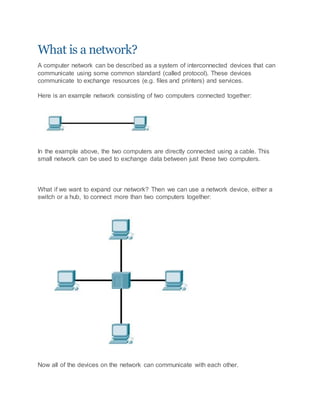
  • 1. What is a network? A computer network can be described as a system of interconnected devices that can communicate using some common standard (called protocol). These devices communicate to exchange resources (e.g. files and printers) and services. Here is an example network consisting of two computers connected together: In the example above, the two computers are directly connected using a cable. This small network can be used to exchange data between just these two computers. What if we want to expand our network? Then we can use a network device, either a switch or a hub, to connect more than two computers together: Now all of the devices on the network can communicate with each other.
  • 2. We'll talk more about hubs and switches in just a moment. For now, just remember that these devices serve as a central point to which all of the computers connect to. OSI & TCP/IP models OSI model OSI (Open Systems Interconnection) model was created by the International Organization for Standardization (ISO), an international standard-setting body. It was designed to be a reference model for describing the functions of a communication system. It has seven layers, with each layer describing a different function of data traveling through a network. Here is the graphical representation of these layers: The layers are usually numbered from the last one, meaning that the Physical layer is consider to be the first layer. It is good to learn these layers, since there will certainly be a couple of questions on the CCNA exam regarding them. Most people learn the mnemonic „Please Do Not Throw Sausage Pizza Away“: So, what is the purpose of these layers? They are most commonly used by vendors. They enable them to implement some functionality into a networking device, which then enables easier interoperability with devices from other vendors. Here is a brief description of each of these layers.
  • 3. Physical – defines how to move bits from one device to another. It details how cables, connectors and network interface cards are going to work and how to send and receive bits. Data Link – encapsulates a packet in a frame. A frame contains a header and a trailer that enable devices to communicate. A header, most commonly, contains a source and a destination MAC address. A trailer contains the Frame Check Sequence field, which is used to detect transmission errors. The data link layer has two sublayers: 1. Logical Link Control – used for flow control and error detection 2. Media Access Control – used for hardware addressing and controlling the access method Network – defines device addressing, routing, and path determination. Device (logical) addressing is used to identify a host on a network (e.g. by its IP address). Transport – segments great chunks of data received from the upper layer protocols. Establishes and terminates connections between two computers. Used for flow control and data recovery. Session – defines how to establish and terminate a session between the two systems. Presentation – defines data formats. Compression and encryption are defined at this layer. Application – this layer is the closest to the user. It enables network applications to communicate with other network applications. The following table shows which protocols reside on which layer: TCP/IPmodel
  • 4. The TCP/IP model was created in the 1970s by the Defense Advance Research Project Agency (DARPA). Like the OSI model, it describes general guidelines for designing and implementing computer protocols. It consists of four layers: Network Access, Internet, Transport, and Application. The following picture show the comparison between the TCP/IP model and OSI model: As you can see, the TCP/IP model has fewer layers than the OSI model. The Application, Presentation, and Session layers of the OSI model are merged in only one layer, Application layer, in the TCP/IP model. Also, Physical and Data Link layers are called Network Access layer in the TCP/IP model. Differences between OSI and TCP/IP model There are some other differences between these two models, besides the obvious difference in the number of layers. OSI model prescribes the steps needed to transfer data over a network and it is very specific in it, defining which protocol is used at each layer and how. The TCP/IP model is not that specific. It can be said that the OSI model prescribes and TCP/IP model describes. Encapsulation The term "encapsulation" is used to describe a process of adding headers and trailers around some data. For example, when you send an email using your favourite email program (like Outlook or Thunderbird) that email is sent from the Application layer to the Transport layer. The Transport layer encapsulates the data and adds its own header (with its own information, such as which port will be used) and passes the data to the Internet layer, which again encapsulates the received data and adds its own header, usually with information about the source and destination IP addresses. The Internet
  • 5. layer than passes the data to the Network Access layer. This layer is the only layer that adds both a header and a trailer. The data is then sent through a physical network link. Each layer adds its own information: The term "decapsulation" refers to the process of removing headers and trailers as data passes from lower to upper layers. This process happens on a computer that is receiving data. Frame, packet, segment Frame - the term "frame" refers to the encapsulated data defined by the Network Access layer. A frame can have a header and a trailer that encapsulate a data section. Packet - the term "packet" is used to describe the encapsulated data defined by the Internet layer. A packet can have a header with the source and destination IP addresses. Segment - the term "segment" describes encapsulated data defined by the Transport layer. A segment can have a header with informations such as source and destionation port numbers, sequence and acknowledgment numbers, etc. Ethernet Ethernet is the most used networking technology for LANs today. It defines wiring and signaling for the Physical layer of the OSI model. For the Data Link layer, it defines frame formats and protocols. Ethernet is described as IEEE 802.3 standard. It uses Carrier Sense Multiple Access with Collision Detection (CSMA/CD) access method and supports speeds up to 100 Gbps. It can use coaxial, twisted pair and fiber optic cables. Ethernet uses frames to with source and destination MAC addresses to deliver data. MAC & IP addresses MAC address A Media Access Control (MAC) address is a 48-bit address that is used for communication between two hosts in an Ethernet environment. It is a hardware address, which means that it is stored in the firmware of the network card. A MAC address is supposed to be globaly unique. Each network card vendor gets its share of addresses (represented by the first 24 bits).
  • 6. The address is written in the form of 12 hexadecimal digits. For example, consider the following MAC address: D8-D3-85-EB-12-E3 Every hexadecimal character represents 4 bits, so the first six hexadecimal characters represent the vendor (in this case, Hewlett Packard). Howto find outyourownMAC address? If you are using Windows, enter the Command Prompt (Start - Programs - Accessories - Command Prompt). Type the ipconfig/all command and you should see a field called Physical address under the Ethernet adapter settings: If you are using Linux, type the ifconfig command. You should see your MAC address referred to as HWaddress.
  • 7. IP address An IP address is a 32-bit number that identifies a host on a network. It is usually written in the form of four decimal numbers seperated by periods (e.g. 10.0.50.1). In contrast to MAC address, an IP address is a logical address. Any device that wants to communicate with other device using TCP/IP needs to have an IP address. It can be configured manually or it can be obtained from a DHCP server. The term "IP address" is usually used for IPv4, which is the fourth version of the IP protocol. A newer version exists, IPv6, and uses 128-bit addressing. Private IP addresses There are three ranges of addresses that can be used in a private network (e.g. your home LAN). These addresses are not routable through the Internet. Private addresses ranges: 10.0.0.0 – 10.255.255.255 172.16.0.0 – 172.31.255.255 192.168.0.0 – 192.168.255.255 How to find out your IP address Windows users: Enter the Command Promt (Start - Programs - Accessories - Command Prompt). Enter ipconfig. You should see a field called IP address.
  • 8. Linux users: Enter ifconfig. You should see a field called inet addr: Network devices Hubs A hub serves as a central point to which all of the hosts in a network connect to. It is an OSI layer 1 device. It receives a signal from one port and sends it out to all other ports. Sometimes it is called a multiport repeater (photo credit: Wikipedia)
  • 9. Today, these devices are considered obsolete and switches are commonly used instead. Hubs have numerous disadvantages. They are not aware of the traffic that passes through them. They create only one large collision domain. A hub typically operates in half duplex. There is also a security issue with hubs since the traffic is forwarded to all ports (except the source port), which makes it possible to capture all traffic on a network with a network sniffer! Switches Like hubs, a switch is used to connect multiple hosts together, but it has many advantages over a hub. Switch is an OSI Layer 2 device, which means that it can inspect received traffic and make forwarding decisions. Each port on a switch is a separate collision domain and can run in a full duplex mode (photo credit: Wikipedia). How switches work Let's take a look at the following example:
  • 10. Host A is trying to communicate with Host B and sends a packet. A packet arrives at the switch, which looks at the destination MAC address. The switch then searches that address in its MAC address table. If the MAC address is found, the switch then forwards the packet only to the port that connected to the frame's destination. If the MAC address is not found, the switch will flood the frame out all other ports. To learn which MAC address is associated with which port, switches examine the source MAC addresses of the receiving packet and store that MAC addresses in their MAC address table. What is a MAC address table? A MAC address table lists which MAC address is connected to which port. It is used by switches to make forwarding decisions. The table is populated by examining the source MAC address of the incoming packet. If the source MAC address of a packet is not present in the table, the switch adds an entry to it's MAC address table. The picture below show how a MAC address table on a switch looks like:
  • 11. Difference between a switch and a bridge A switch is sometimes called a multiport bridge, but there are differences between these two devices. A bridge usually has fewer ports than switch. A switch operates faster because it is hardware-based, which means that it uses chips (ASICs) when making forwarding decisions. In contrast, a bridge is software based. A switch can also have multiple spanning-tree instances while a bridge can have only one. Switches can also have multiple broadcast domains, one per VLAN. Routers A router is a device that routes packets from one network to another. A router is most commonly an OSI Layer 3 device. Routers divide broadcast domains and have traffic filtering capabilities. The picture below shows a typical home router: How routers work
  • 12. A router uses IP addresses to figure out where to send packets. If two hosts from different networks want to communicate, they will need a router between them to route packets For example, check the following scenario: Host A and host B are on different networks. If host A wants to communicate with host B, it will have to send a packet to the router. The router receives the packet and checks the destination IP address. If the destination IP address is in the routing table, the router will forward the packet out the interface associated with that network. What is a routing table? A routing table lists a route for every network that a router can reach. It can be statically configured (using IOS commands) or dynamically learned (using a routing protocol). It is used by routers when deciding where to forward packets. The picture below shows how a routing table looks like: The command to display an IP routing table is show ip route. In the picture above, you can see that this router has two directly connected subnets. Let's take a closer look at the first entry in the routing table:
  • 13. „C“ means that the route is a directly connected route. The network in question is 10.0.0.0/8, and the router will forward each packet destined for that network out interface FastEthernet0/1. NOTE – in Windows, you can use the netstat –r command to display the routing table of your system. Types of Ethernet cabling There are three cable types commonly used for Ethernet cabling: coaxial, twisted pair, and fiber-optic cabling. In today's LANs, the twisted pair cabling is the most popular type of cabling, but the fiber-optic cabling usage is increasing, especially in high performance networks. Coaxial cabling is generally used for cable Internet access. We will explain all three types of cabling. We will also explain a difference between a straight-through and crossover cable. Coaxialcabling Coaxial cable has an inner conductor that runs down the middle of the cable. The conductor is surrounded by a layer of insulation which is then surrounded by another conducting shield, which makes this type of cabling resistant to the outside interference. This type of cabling comes in two types, thinnet and thicknet. Both types have a maximum transmission speed of 10 Mbps. Coaxial cabling was used for computer networks, but today are largely replaced by twisted-pair cabling (Photo credit: Wikipedia)
  • 14. Twisted-pair cabling A twisted-pair cable has four pair of wires. These wires are twisted around each other to reduce crosstalk and outside interference. This type of cabling is common in most current LANs. Twisted-pair cabling can be used for telephone and network cabling. It comes in two versions, UTP (Unshielded Twisted-Pair) and STP (Shielded Twisted-Pair). The difference between these two is that an STP cable has an additional layer of insulation that protects data from outside interferences. Here you can see how a twisted pair cable looks like (Photo credit: Wikipedia):
  • 15. A twisted-pair cable uses 8P8C connector, sometimes wrongly referred to as RJ45 connector (Photo credit: Wikipedia). Fiber-optic cabling This type of cabling uses optical fibers to transmit data in the form of light signals. The cables have strands of glass surrounded by a cladding material (Photo credit: Wikipedia).
  • 16. This type of cabling can support greater cable lengths than any other cabling type (up to a couple of miles). The cables are also immune to electromagnetic interference. As you can see, this cabling method has many advantages over other methods but it's drawback is that it is the most expensive type of cabling. There are two types of fiber-optic cables: • Single-mode fiber (SMF) - uses only a single ray of light to carry data • Multi-mode fiber (MMF) - uses multiple rays of light to carry data Two types of connectors are commonly used: • ST (Straight-tip connector) • SC (Subscriber connector) Types of Ethernet cables Ethernet cables can come in two forms: Straight-through cable - it has identical wiring on both ends (pin 1 on one end of the cable is connected to pin 1 at the other end of the cable, pin 2 is connected to pin 2 etc.). This type of cable is used to connect: • computer to hub • computer to switch • router to hub • router to switch Computers and routers use wires 1 and 2 to transmit data and wires 3 and 6 to receive data. Hubs and switches use wires 1 and 2 to receive data and wires 3 and 6 to send data. That is why, if you want to connect two computers together, you will need a crossover cable. Crossover cable – wire pairs are swapped, which means that different pins are connected together - pin 1 on one end of the cable is connected to pin 3 on the other
  • 17. end, pin 2 on one end is connected to pin 6 on the other end (Photo credit: Wikipedia). This type of cable is used when you need to connect two devices that use the same wires to send and the same wires to receive data. For example, consider connecting two computers together. If you use straight-through cable, with identical wiring in both ends, both computers will use wires 1 and 2 to send data. If computer A sends some packets to computer B, computer A will send that data using wires 1 and 2. That will cause a problem because computers expect packets to be received on wires 3 and 6, and your network will not work properly Wide area network The term „wide area network“ is used to describe a network that spans multiple geographic locations. Consider an example. A company has two offices, one in London and one in Berlin. Both offices have a LAN. If the company connects these two LANs together using WAN technology, a WAN is created. The key difference between LANs and WANs is that the company usually doesn't own WAN infrastructure. A company usually leases WAN services from a service provider. Frame Relay, ATM and X.25 are different types of WAN technologies. The Internet can also be considered a WAN Local area network & Metropolitan area network Localarea network(LAN)
  • 18. The term "local area network" is commonly used to describe a network of devices in a limited area (a house, office, building...). This type of network is usually capable of achieving high data transfer rate (up to 10 Gbps!) at low cost. Some of the most popular LAN technologies are Ethernet, Token Ring and FDDI. Most LAN networks use TCP/IP to communicate. Twisted-pair cabling is usually used in a LAN. Examples of this type of network are a small office network inside a single building or your home network. Metropolitan area network(MAN) The term „metropolitan area network“ is used to describe a network in a single metropolitan area, hence the name. This type of network is usually bigger than a LAN and smaller than a WAN. An example of this type of network would be a network that connects two company offices inside the same city. Local area network & Metropolitan area network Localarea network(LAN) The term "local area network" is commonly used to describe a network of devices in a limited area (a house, office, building...). This type of network is usually capable of achieving high data transfer rate (up to 10 Gbps!) at low cost. Some of the most popular LAN technologies are Ethernet, Token Ring and FDDI. Most LAN networks use TCP/IP to communicate. Twisted-pair cabling is usually used in a LAN. Examples of this type of network are a small office network inside a single building or your home network. Metropolitan area network(MAN) The term „metropolitan area network“ is used to describe a network in a single metropolitan area, hence the name. This type of network is usually bigger than a LAN and smaller than a WAN. An example of this type of network would be a network that connects two company offices inside the same city. Classes of IP addresses TCP/IP defines five classes of IP addresses: class A, B, C, D, and E. Each class has a range of valid IP addresses. The value of the first octet determines the class. IP addresses from the first three classes (A, B and C) can be used for host addresses. The other two classes are used for other purposes (class D for multicast and class E for experimental purposes). Classes of IP addresses:
  • 19. Special IP address ranges: 0.0.0.0/8 - addresses used to communicate with the current network 127.0.0.0/8 - loopback addresses 169.254.0.0/16 - link-local addresses (APIPA) Subnet mask An IP address is divided into two parts: network and host parts. For example, an IP class A address consists of 8 bits identifying the network and 24 bits identifying the host. This is because the default subnet mask for a class A IP address is 8 bits long. (or, written in dotted decimal notation, 255.0.0.0). What does it mean? Well, like an IP address, a subnet mask also consists of 32 bits. Computers use it to determine the network part and the host part of an address. The 1s in the subnet mask represent a network part, the 0s a host part. Computers works only with bits. The math used to determine a network range is binary AND. Let's say that we have the IP address of 10.0.0.1 with the default subnet mask of 8 bits (255.0.0.0). First, we need to convert the IP address to binary: IP address: 10.0.0.1 = 00001010.00000000.00000000.00000001 Subnet mask 255.0.0.0 = 11111111.00000000.00000000.0000000 Computers then use the AND operation to determine the network number:
  • 20. The computer can then determine the size of the network. Only IP addresses that begins with 10 will be in the same network. So, in this case, the range of addresses in this network is 10.0.0.0 – 10.255.255.255. NOTE - A subnet mask must always be a series of 1s followed by a series of 0s. Traceroute Traceroute is a CLI (Command-line interface)-based tool used to identify the path used by a packet to reach its target. This tool also uses ICMP messages, but unlike ping, identifies every router in a path. Traceroute is useful when troubleshooting network problems because it can help identify where exactly the problem is. Traceroute sends a series of ICMP echo request packets to a destination. First series of messages has a Time to Live (TTL) parameter set to 1, which means that the first router in a path will discard the packet and send an ICMP Time Exceeded message. TTL is then increased by one until the destination host is reached and an ICMP echo reply message is received. Originating host can then use received ICMP messages to identify all routers in a path. The traceroute command on Windows is named tracert. On Unix and Cisco IOS traceroute it is invoked using the traceroute command. Here is an example showing the tracert command in Windows:
  • 21. Traceroute on Unix-like operating systems Traceroute command on Unix works slighty different than the Windows version. It uses UDP packets with a large destination port number (33434 to 33534) that is unlikely to be used by any application at the destination host. Like the Windows version of the command, traceroute on Unix uses TTL to get the IP addresses of the intermediary routers. When a destination host is reached, it replies with an ICMP port unreachable message.