Project main page 2
•
0 likes•36 views

This document provides a list of components, tables, and figures for a project on a propeller LED display. It includes 15 components in the components list, with details on the component name, rating/type, and quantity of each. The tables list includes one table with 4 columns describing the 8051 microprocessor pin descriptions. The figures list includes 13 figures with descriptions related to the principles, diagrams, circuits, and mechanical aspects of the propeller LED display project.

Recommended
More Related Content
What's hot
What's hot (18)
Similar to Project main page 2
Similar to Project main page 2 (20)
More from Ranjan kumar
More from Ranjan kumar (18)
Recently uploaded
Recently uploaded (20)
Project main page 2
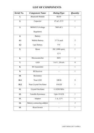
- 1. (AIET/DOEE/2017-18/PR/i) LIST OF COMPONENTS Serial No. Component Name Rating/Type Quantity 1. Bluetooth Module HC05 1 2. Capacitor 47 µF, 25 V 1 3. MOSFET (Voltage Regulator) 7805 (IC) 1 4. 4.1 4.2 Battery Mobile Battery Lipo Battery 3.7 V each 9 V 2 1 5. Motor DC (3000 rpm), 12 V 1 6. Microcontroller 8051 1 7. LED 3.6 V , 20 mA 8 8. IR Transmitter - 1 9. IR Receiver - 1 10. 10.1 10.2 Resistance Near LED Near Crystal Oscillator 100 Ώ 10 K Ώ 8 1 11. Crystal Oscillator 11.0290 MHz 12. Variable Resistance Upto 10 K Ώ 1 13. Adaptor 1 A, 12 V 1 14. Battery connecting addptor - 3 15. Reset Switch - 1
- 2. (AIET/DOEE/2017-18/PR/ii) LIST OF TABLE Table No. Table Description Page No. 4.1 Description of 8051 microprocessor pin 33
- 3. (AIET/DOEE/2017-18/PR/iii) LIST OF FIGURE Figure No. Figure Description Page No. 1.1 Principle of vision of persistence technology 3 1.1 (b) Principle of vision of persistence technology 3 1.1 (b) Principle of vision of persistence technology 3 1.2 Functional Diagram of propeller LED display 4 1.3 Flow chat diagram of propeller LED display 5 2.1 General Block Diagram of Propeller LED Display 6 2.2 Simple Block Diagram of Propeller LED Display 7 2.3 Crystal of Interrupter Module 8 2.3 (a) Crystal of Interrupter Module 8 2.3 (b) Crystal of Interrupter Module 8 2.4 Pin diagram of 8051 microcontroller 10 2.5 LED Module 11 2.6 Block diagram of DC motor 12 2.7 BATTERY 13 2.7(a) 9V DC supply battery 13 2.7(b) 3.7V Li Ion battery 13 2.8 DC supply battery adapter 13 2.9 IR Sensor circuit 14 2.10 IR Sensor Circuit diagram 15 2.11 PIR sensor 17 2.12 Ultrasonic sensor 17 2.13 (Figure: 16- Bluetooth Module HC05) 18 3.1 Mechanical assembly 19 3.2 Circuit Diagram of Power Supply Module 20
- 4. (AIET/DOEE/2017-18/PR/iv) 3.3 LED circuit 21 3.4 Front view of module of propeller led display 22 3.5 Final working model of propeller LED display 23 4.1 Circuit module of PCB board 25 4.2 8051 microcontroller basic circuit 26 4.3 ATmega16, 8051 pin diagram 27 4.4 Crystal of ATmega16, 8051 pin 29 6.1 Getting started with KEIL 1 38 6.2 Getting started with KEIL 2 39 6.3 Getting started with KEIL 3 40 6.4 Getting started with KEIL 4 41 6.5 Getting started with KEIL 5 42 6.6 Getting started with KEIL 6 43
- 5. (AIET/DOEE/2017-18/PR/v) CONTENTS S. No. Title Page No. CERTIFICATE…………………………………….............. ACKNOWLEDGEMENT…………………………………. ABSTRACT………………………………………………… LIST OF COMPONENTS…………………………………. i LIST OF TABLE…………………………………………… ii LIST OF FIGURE………………………………………….. iii-iv CONTENT………………………………………….............. v-vi CHAPTER-1 Introduction……………………………………….................. 1 1.1 About the project…………………………………………….. 1 1.2 Basic principle of propeller led display……………................ 2 1.3 Functional diagram…………………………………............... 4 1.4 Flow chart diagram…………………………………............... 5 CHAPTER-2 2.1 Methodology of propeller led display ………………………. 6 2.2 Overview of block diagram………………………………….. 7 CHAPTER-3 Mechanical assembly………………………………………... 19 3.1 Power supply module………………………………………... 20 3.2 Front view of module of propeller led display………………. 22 CHAPTER-4 PCB board design……………………………………………. 24 4.1 PCB designing steps…………………………………………. 24 4.2 8051 microcontroller basic circuit……………….................... 24 4.3 ATMEGA 16, 8051 pin diagram…………………………….. 26 4.4 Pin descriptions VCC………………………………………... 27 4.5 Features of AT MEGA 16, 8051 microprocessor…………… 29 CHAPTER-5 Software design……………………………………………… 33
- 6. (AIET/DOEE/2017-18/PR/vi) 5.1 Software’s used……………………………………………… 33 5.2 Program converting in the hex file…………………............... 37 CHAPTER-6 6.1 Using the Keil Environment…………………......................... 38 6.2 FUTURE SCOPE OF PROPELLER LED DISPLAY…………………………………………………… 44 6.3 APPLICATIONS…………………………………………… 44 CONCLUSION……………………………………............... 45 REFERENCES……………………………………………... 46