
Recommended
More Related Content
Similar to Repair lexia 3 pcb to avoid activation relay, connection failure etc
Similar to Repair lexia 3 pcb to avoid activation relay, connection failure etc (20)
Recently uploaded
Recently uploaded (20)
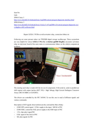
Repair lexia 3 pcb to avoid activation relay, connection failure etc
- 1. Item No: Link: SP08-C lexia 3 http://www.diyobd2.fr/wholesale/lexia-3-pp2000-citroen-peugeot-diagnostic-interface.html SP08-D lexia 3 http://www.diyobd2.fr/wholesale/lexia-3-lexia-3-v47-pp2000-v25-citroen-peugeot-diagnostic-ave c-diagbox-v601-software.html Repair LEXIA 3 PCB to avoid activation relay, connection failure etc Following are some pictures taken via TDS2000 digital storage oscilloscope. These screenshots are very helpful for whose LEXIA 3 PSA Es- evolution pp2000 DiagBox encounter activation relay on electronic board of the same name or communication failure on the vehicle computers etc problems. The steering each relay is madewith the twoset of components: 8-bit serial-in, serial or parallel-out shift register with output latches (HCT 595) + High Voltage, High Current Darlington Transistor Arrays (MC1413BDG or ULN2003). The drivers are controlled by the PIC 16F684. To run this one in need of different signals and various commands. Description of ICP signals observed between the card and the Micro Relay: - COM VPP control signal / 12Vdc supply to the input / MCLR of PIC - COM VDD, control the 5Vdc power supply to the VDD input of PIC - / CS, chip select signal PIC - CLK signal of the clock of PIC - SO, data signals for PIC
- 2. Screenshot COM VPP Control signal and VDD control signal on a functional interface:
- 3. COM VPP control signal/12VDC power goes from 0 to + 12Vdc of thatconnects the battery 12Vdc on the relay card (jack connection on ODB). COM VDD signal, it increases from 5Vdc to 0Vdc when the app is launched (I did the tests with lexia3 interface only) During a diagnostic in GLOBAL TEST, that's what happens (warning on the screen of the oscilloscope, we see signals of a non-functional interface):
- 4. Screenshot of clock signal CLK PIC on a functional interface: The clock frequency is 6.45kHz. Screenshot of clock signal CLK PIC on a non-functional interface:
- 5. Screenshot of clock signal CLK and /CS signal PIC on a functional interface:
- 6. Screenshot of clock signal CLK and /CS signal PIC on a non-functional interface: Interface optocoupler 9871A2 instead of 063N HCPL!
- 7. Screenshot of clock signal CLK and SO data signal PIC on a functional interface:
- 9. Screenshot of clock signal CLK and SO data signal PIC on a non-functional interface: Interface optocouplers 9871A2 instead of HCPL 063N!
- 10. Screenshot of /CS signal and SO data PIC signal on a functional interface: