Unit-V Special ICs
•
1 like•57 views

IC555 Timer, Monostable and Astable modes of operation; voltage regulators - fixed voltage regulators, adjustable voltage regulators - switching regulators.

Recommended
Recommended
More Related Content
What's hot
What's hot (20)
Similar to Unit-V Special ICs
Similar to Unit-V Special ICs (20)
More from Dr.Raja R
More from Dr.Raja R (20)
Recently uploaded
Recently uploaded (20)
Unit-V Special ICs
- 1. Presented by Dr. R. RAJA, M.E., Ph.D., Assistant Professor, Department of EEE, Muthayammal Engineering College, (Autonomous) Namakkal (Dt), Rasipuram – 637408 19EEC03-Linear Integrated Circuits and Its Applications Unit-V Special ICs MUTHAYAMMAL ENGINEERING COLLEGE (An Autonomous Institution) (Approved by AICTE, New Delhi, Accredited by NAAC, NBA & Affiliated to Anna University), Rasipuram - 637 408, Namakkal Dist., Tamil Nadu.
- 2. Unit-V Special ICs IC555 Timer, Monostable and Astable modes of operation; voltage regulators - fixed voltage regulators, adjustable voltage regulators - switching regulators. 9/23/2020 2
- 3. 555 Timer and Working 555 Timer Integrated Circuit (IC) is a monolithic timing circuit introduced by Signetic Corporation in 1970. This device can be easily configured to produce accurate, highly-stable time delays or oscillations, just by adding a very few extra timing components. 555 timer IC is available as a 8-pin metal can or as 8- or 14-pin or 16-pin DIP. Depending on the manufacturing company, the internal structure of the IC has around 23 transistors, 2 diodes and 16 resistors. 9/23/2020 3
- 4. Contd.. 9/23/2020 4 The pin configuration of 8-pin DIP and 14-pin DIP are as shown by Figure 1a and 1b, respectively.
- 5. Contd.. Apart from these, they are also available these days in their CMOS version like that of Motorola MC1455. The working of this IC can be understood by analyzing its internal structure which is shown in terms of block diagram (for 8-pin DIP) in Figure 2. From this, the IC is seen to be composed of A resistive network formed by three equal resistors (R) It is due to these three 5 KΩ resistors, the IC bears its name as 555 timer. These are arranged in voltage divider configuration and as a result provide the voltage values of 2⁄3 VCC and 1⁄3 VCC along their chain. Two Comparators These two devices are meant to compare the user-provided input values with their reference levels and accordingly trigger the output of the flip-flop. 9/23/2020 5
- 7. Contd.. Two Transistors These are associated with discharge and reset operations of the device. One SR flip-flop This flip-flop will be either set or reset depending on the output from the comparators. An Inverter Inverter is used to obtain the output from the device by complementing the flip- flop’s Q̅ output. 9/23/2020 7
- 8. Contd.. Following is a brief description on the function associated with each of its pins Ground (Pin 1 of 8-pin and Pin 3 of 14-pin package): Used a reference with which each of the voltage is measured. Trigger (Pin 2 of 8-pin and Pin 4 of 14-pin package): This pin is used to provide trigger to the circuit when the device will be configured to behave like a monostable multivibrator. As evident from Figure 2, it is seen that this pin is connected as an input to the comparator C2 which compares it with 1⁄3 VCC, fed as an input to its other terminal. As a result, when the user-provided negative pulse exceeds 1⁄3 VCC (obtained from the resistive network), the output of this comparator goes high. 9/23/2020 8
- 9. Contd.. This causes the output Q of the SR flip-flop to become zero, thereby pulling its Q̅ pin high which makes the output of the inverter to go low, thereby resulting in a high output from the IC. Output (Pin 3 of 8-pin and Pin 5 of 14-pin package): This is the pin at which the output of the IC can be obtained. 555 timer IC provides two options for the user to load this pin viz., (i) Normally on load configuration where the load is connected between the Supply and the Output pins and (ii) Normally off load configuration where the load is connected between the Ground and the Output pins. 9/23/2020 9
- 10. Contd.. Reset (Pin 4 of 8-pin and Pin 6 of 14-pin package): This pin can be used by the user to reset the IC as the user-provided negative going pulse on this pin switches OFF the associated transistor. This is because, a logic low on this pin causes the output of the flip-flop to go high, turning ON the discharge transistor. However, usually this pin will be connected to +VCC when not in use so as to avoid false triggering. Control Voltage (Pin 5 of 8-pin and Pin 9 of 14-pin package): This pin is used to control the levels of threshold as well as triggering. 9/23/2020 10
- 11. Contd.. In addition, this pin can be used to control the pulse width of the output waveform as the voltage applied at this pin decides the condition at which the output of the comparator (C1) switches its state. The same regulation in the output waveform can be even experienced by connecting a potentiometer to this pin. Next, it is to be noted that when this pin is to be left unused, it is to be bypassed to ground via 0.01 μF capacitor in order to get rid of noise issue. Threshold (Pin 6 of 8-pin and Pin 10 of 14-pin package): This pin is connected to the positive terminal of the comparator C1 which compares the applied voltage with 2⁄3 VCC. 9/23/2020 11
- 12. Contd.. Next, when the user provided voltage exceeds this reference level of 2⁄3 VCC, the output of C1 goes high, and thus the flip-flop’s output (Q) will be set. Due to this, the complement of its output (Q̅ ) will go low, resulting in a high output from the inverter, which will be nothing but the output of the IC. Discharge (Pin 7 of 8-pin and Pin 12 of 14-pin package): This pin is connected to the collector terminal of the internal transistor in 555 timer IC. Generally, a capacitor will be connected between this terminal and ground. This capacitor discharges through the transistor when it saturates, a phenomenon experienced when the output of comparator C1 sets the flip-flop indicating that the threshold voltage has increased in comparison with that of the control voltage. 9/23/2020 12
- 13. Contd.. On the other hand, if the negative-going trigger pulse exceeds 1⁄3 VCC, then the output of the flip-flop goes low as the lower comparator’s output will go high. This inturn turns OFF the transistor during which the capacitor attached to its terminal starts to charge at a rate decided by the external resistor and the capacitor. Supply (Pin 8 of 8-pin and Pin 13 of 14-pin package): This pin is used to provide a voltage within the range of +5V to +18V wrt ground. These ICs are most extensively used in electronic industry as they are versatile, compact, cheap and highly reliable. 9/23/2020 13
- 14. Contd.. Further, these devices are seen to be used for a wide variety of applications wherein they act as oscillators (astable or monostable or bistable), one-shot or delay timers, pulse generators, LED or lamp flashers, alarm or tone generators, frequency dividers, logic clocks, power suppliers, DC-DC converters, digital logic probes, analog frequency meters, tachometers, temperature measuring devices, control devices, voltage regulators, etc. 9/23/2020 14
- 15. Monostable Modes of Operation Using 555 Timer The operation and output of the 555 timer monostable is exactly the same as that for the transistorised one we look at previously in the Monostable Multivibrators tutorial. The difference this time is that the two transistors have been replaced by the 555 timer device. Consider the 555 timer monostable circuit below. When a negative ( 0V ) pulse is applied to the trigger input (pin 2) of the Monostable configured 555 Timer oscillator, the internal comparator, (comparator No1) detects this input and “sets” the state of the flip-flop, changing the output from a “LOW” state to a “HIGH” state. This action in turn turns “OFF” the discharge transistor connected to pin 7, thereby removing the short circuit across the external timing capacitor, C1. 9/23/2020 15
- 17. Contd.. This action allows the timing capacitor to start to charge up through resistor, R1 until the voltage across the capacitor reaches the threshold (pin 6) voltage of 2/3Vcc set up by the internal voltage divider network. At this point the comparators output goes “HIGH” and “resets” the flip-flop back to its original state which in turn turns “ON” the transistor and discharges the capacitor to ground through pin 7. This causes the output to change its state back to the original stable “LOW” value awaiting another trigger pulse to start the timing process over again. Then as before, the Monostable Multivibrator has only “ONE” stable state. 9/23/2020 17
- 18. Contd.. The Monostable 555 Timer circuit triggers on a negative-going pulse applied to pin 2 and this trigger pulse must be much shorter than the output pulse width allowing time for the timing capacitor to charge and then discharge fully. Once triggered, the 555 Monostable will remain in this “HIGH” unstable output state until the time period set up by the R1 x C1 network has elapsed. The amount of time that the output voltage remains “HIGH” or at a logic “1” level, is given by the following time constant equation. Where, t is in seconds, R is in Ω and C in Farads. 9/23/2020 18
- 19. Contd.. 555 Timer Example No1 A Monostable 555 Timer is required to produce a time delay within a circuit. If a 10uF timing capacitor is used, calculate the value of the resistor required to produce a minimum output time delay of 500ms. 500ms is the same as saying 0.5s so by rearranging the formula above, we get the calculated value for the resistor, R as: The calculated value for the timing resistor required to produce the required time constant of 500ms is therefore, 45.5KΩ. 9/23/2020 19
- 20. Contd.. However, the resistor value of 45.5KΩ does not exist as a standard value resistor, so we would need to select the nearest preferred value resistor of 47kΩ which is available in all the standard ranges of tolerance from the E12 (10%) to the E96 (1%), giving us a new recalculated time delay of 517ms. If this time difference of 17ms (500 – 517ms) is unacceptable instead of one single timing resistor, two different value resistor could be connected together in series to adjust the pulse width to the exact desired value, or a different timing capacitor value chosen. We now know that the time delay or output pulse width of a monostable 555 timer is determined by the time constant of the connected RC network. 9/23/2020 20
- 21. Contd.. If long time delays are required in the 10’s of seconds, it is not always advisable to use high value timing capacitors as they can be physically large, expensive and have large value tolerances, e.g, ±20%. One alternative solution is to use a small value timing capacitor and a much larger value resistor up to about 20MΩ’s to produce the require time delay. Also by using one smaller value timing capacitor and different resistor values connected to it through a multi-position rotary switch, we can produce a Monostable 555 timer oscillator circuit that can produce different pulse widths at each switch rotation such as the switchable Monostable 555 timer circuit shown below. 9/23/2020 21
- 23. Contd.. We can manually calculate the values of R and C for the individual components required as we did in the example above. However, the choice of components needed to obtain the desired time delay requires us to calculate with either kilohm’s (KΩ), Megaohm’s (MΩ), microfarad’s (μF) or picafarad’s (pF) and it is very easy to end up with a time delay that is out by a factor of ten or even a hundred. We can make our life a little easier by using a type of chart called a “Nomograph” that will help us to find the monostable multivibrators expected frequency output for different combinations or values of both the R and C. For example, So by selecting suitable values of C and R in the ranges of 0.001uF to 100uF and 1kΩ to 10MΩ respectively, 9/23/2020 23
- 24. Contd.. Monostable Nomograph We can read the expected output frequency directly from the nomograph graph thereby eliminating any error in the calculations. In practice the value of the timing resistor for a monostable 555 timer should not be less than 1kΩ or greater than 20MΩ. 9/23/2020 24
- 25. Astable Modes of Operation Using 555 Timer Astable Multivibrators are free running oscillators which oscillate between two states continually producing two square wave output waveforms. Regenerative switching circuits such as Astable Multivibrators are the most commonly used type of relaxation oscillator because not only are they simple, reliable and ease of construction they also produce a constant square wave output waveform. Unlike the Monostable Multivibrator or the Bistable Multivibrator we looked at in the previous tutorials that require an “external” trigger pulse for their operation, the Astable Multivibrator has automatic built in triggering which switches it continuously between its two unstable states both set and reset. 9/23/2020 25
- 26. Contd.. The Astable Multivibrator is another type of cross-coupled transistor switching circuit that has NO stable output states as it changes from one state to the other all the time. The astable circuit consists of two switching transistors, a cross-coupled feedback network, and two time delay capacitors which allows oscillation between the two states with no external triggering to produce the change in state. In electronic circuits, astable multivibrators are also known as Free-running Multivibrator as they do not require any additional inputs or external assistance to oscillate. 9/23/2020 26
- 27. Contd.. Astable oscillators produce a continuous square wave from its output or outputs, (two outputs no inputs) which can then be used to flash lights or produce a sound in a loudspeaker. The basic transistor circuit for an Astable Multivibrator produces a square wave output from a pair of grounded emitter cross-coupled transistors. Both transistors either NPN or PNP, in the multivibrator are biased for linear operation and are operated as Common Emitter Amplifiers with 100% positive feedback. This configuration satisfies the condition for oscillation when: ( βA = 1∠ 0o ). 9/23/2020 27
- 28. Contd.. This results in one stage conducting “fully-ON” (Saturation) while the other is switched “fully-OFF” (cut-off) giving a very high level of mutual amplification between the two transistors. Conduction is transferred from one stage to the other by the discharging action of a capacitor through a resistor as shown below. 9/23/2020 28
- 30. Contd.. Assume a 6 volt supply and that transistor, TR1 has just switched “OFF” (cut- off) and its collector voltage is rising towards Vcc, meanwhile transistor TR2 has just turned “ON”. Plate “A” of capacitor C1 is also rising towards the +6 volts supply rail of Vcc as it is connected to the collector of TR1 which is now cut-off. Since TR1 is in cut-off, it conducts no current so there is no volt drop across load resistor R1. The other side of capacitor, C1, plate “B”, is connected to the base terminal of transistor TR2 and at 0.6v because transistor TR2 is conducting (saturation). 9/23/2020 30
- 31. Contd.. Therefore, capacitor C1 has a potential difference of +5.4 volts across its plates, (6.0 – 0.6v) from point A to point B. Since TR2 is fully-on, capacitor C2 starts to charge up through resistor R2 towards Vcc. When the voltage across capacitor C2 rises to more than 0.6v, it biases transistor TR1 into conduction and into saturation. The instant that transistor, TR1 switches “ON”, plate “A” of the capacitor which was originally at Vcc potential, immediately falls to 0.6 volts. This rapid fall of voltage on plate “A” causes an equal and instantaneous fall in voltage on plate “B” therefore plate “B” of C1 is pulled down to -5.4v (a reverse charge) and this negative voltage swing is applied the base of TR2 turning it hard “OFF”. One unstable state. 9/23/2020 31
- 32. Contd.. Transistor TR2 is driven into cut-off so capacitor C1 now begins to charge in the opposite direction via resistor R3 which is also connected to the +6 volts supply rail, Vcc. Thus the base of transistor TR2 is now moving upwards in a positive direction towards Vcc with a time constant equal to the C1 x R3 combination. However, it never reaches the value of Vcc because as soon as it gets to 0.6 volts positive, transistor TR2 turns fully “ON” into saturation. This action starts the whole process over again but now with capacitor C2 taking the base of transistor TR1 to -5.4v while charging up via resistor R2 and entering the second unstable state. 9/23/2020 32
- 33. Contd.. Then we can see that the circuit alternates between one unstable state in which transistor TR1 is “OFF” and transistor TR2 is “ON”, and a second unstable in which TR1 is “ON” and TR2 is “OFF” at a rate determined by the RC values. This process will repeat itself over and over again as long as the supply voltage is present. The amplitude of the output waveform is approximately the same as the supply voltage, Vcc with the time period of each switching state determined by the time constant of the RC networks connected across the base terminals of the transistors. 9/23/2020 33
- 34. Contd.. As the transistors are switching both “ON” and “OFF”, the output at either collector will be a square wave with slightly rounded corners because of the current which charges the capacitors. This could be corrected by using more components as we will discuss later. If the two time constants produced by C2 x R2 and C1 x R3 in the base circuits are the same, the mark-to-space ratio ( t1/t2 ) will be equal to one-to-one making the output waveform symmetrical in shape. By varying the capacitors, C1, C2 or the resistors, R2, R3 the mark-to-space ratio and therefore the frequency can be altered. 9/23/2020 34
- 35. Contd.. We saw in the RC Discharging tutorial that the time taken for the voltage across a capacitor to fall to half the supply voltage, 0.5Vcc is equal to 0.69 time constants of the capacitor and resistor combination. Then taking one side of the astable multivibrator, the length of time that transistor TR2 is “OFF” will be equal to 0.69T or 0.69 times the time constant of C1 x R3. Likewise, the length of time that transistor TR1 is “OFF” will be equal to 0.69T or 0.69 times the time constant of C2 x R2 and this is defined as. 9/23/2020 35
- 36. Contd.. Astable Multivibrators Periodic Time Where, R is in Ω’s and C in Farads. By altering the time constant of just one RC network the mark-to-space ratio and frequency of the output waveform can be changed but normally by changing both RC time constants together at the same time, the output frequency will be altered keeping the mark-to-space ratios the same at one-to- one. If the value of the capacitor C1 equals the value of the capacitor, C2, C1 = C2 and also the value of the base resistor R2 equals the value of the base resistor, R3, R2 = R3 then the total length of time of the Multivibrators cycle is given below for a symmetrical output waveform. 9/23/2020 36
- 37. Contd.. 9/23/2020 37 Frequency of Oscillation Where, R is in Ω’s, C is in Farads, T is in seconds and ƒ is in Hertz. and this is known as the “Pulse Repetition Frequency”. So Astable Multivibrators can produce TWO very short square wave output waveforms from each transistor or a much longer rectangular shaped output either symmetrical or non-symmetrical depending upon the time constant of the RC network as shown below.
- 39. Contd.. Astable Multivibrator Example No1 An Astable Multivibrators circuit is required to produce a series of pulses at a frequency of 500Hz with a mark-to-space ratio of 1:5. If R2 = R3 = 100kΩ, calculate the values of the capacitors, C1 and C2 required. 9/23/2020 39
- 40. Contd.. and by rearranging the formula above for the periodic time, the values of the capacitors required to give a mark-to-space ratio of 1:5 are given as: The values of 4.83nF and 24.1nF respectively, are calculated values, so we would need to choose the nearest preferred values for C1 and C2 allowing for the capacitors tolerance. 9/23/2020 40
- 41. Contd.. In fact due to the wide range of tolerances associated with the humble capacitor the actual output frequency may differ by as much as ±20%, (400 to 600Hz in our simple example) from the actual frequency needed. If we require the output astable waveform to be non-symmetrical for use in timing or gating type circuits, etc, we could manually calculate the values of R and C for the individual components required as we did in the example above. However, when the two R’s and C´s are both equal, we can make our life a little bit easier for ourselves by using tables to show the astable multivibrators calculated frequencies for different combinations or values of both R and C. For example, 9/23/2020 41
- 42. Contd.. Astable Multivibrator Frequency Table 9/23/2020 42
- 43. Contd.. Pre-calculated frequency tables can be very useful in determining the required values of both R and C for a particular symmetrical output frequency without the need to keep recalculating them every time a different frequency is required. By changing the two fixed resistors, R2 and R3 for a dual-ganged potentiometer and keeping the values of the capacitors the same, the frequency from the Astable Multivibrators output can be more easily “tuned” to give a particular frequency value or to compensate for the tolerances of the components used. For example, selecting a capacitor value of 10nF from the table above. By using a 100kΩ’s potentiometer for our resistance, we would get an output frequency that can be fully adjusted from slightly above 71.4kHz down to 714Hz, some 3 decades of frequency range. Likewise a capacitor value of 47nF would give a frequency range from 152Hz to well over 15kHz. 9/23/2020 43
- 44. Voltage Regulators What is Voltage Regulation A voltage regulator is an electronic or electrical device that can sustain the voltage of power supply within suitable limits. The electrical equipment connected to the voltage source should bear the value of the voltage. The source voltage should be in a certain range which is acceptable for the connected pieces of equipment. This purpose is fulfilled by implementing a voltage regulator. A voltage regulator – as the same suggests – regulates the voltage, regardless of the adjustments in the input voltage or connected load. 9/23/2020 44
- 45. It works as a shield for protective devices from damage. It can regulate both AC or DC voltages, depending on its design. 9/23/2020 45 Contd..
- 46. Types of Voltage Regulators There are two main types of voltage regulators available: Linear Voltage Regulators Switching Voltage Regulators These can be further classified into more specific voltage regulators, as discussed below. 9/23/2020 46 Contd..
- 47. Linear Voltage Regulator This type of voltage regulator performs as a voltage divider. It employs FET in Ohmic region. The steady output is sustained by varying the resistance of voltage regulator with respect to the load. Generally, these types of voltage regulator are of two types: Series voltage regulator Shunt voltage regulator 9/23/2020 47 Contd..
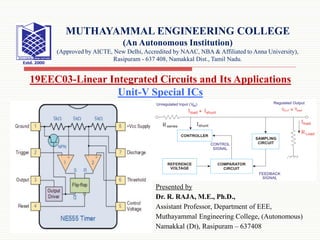
- 48. Series Voltage Regulator It implements a variable element positioned in series with the connected load. The steady output is sustained by varying the resistance of this element with respect to the load. They are of two types that are briefed below. Discrete Transistor Series Voltage Regulator Here from the block diagram, we can see an unregulated input is first fed into a controller. It actually controls the input voltage magnitude and given to the output. This output is given to the feedback circuit. It is sampled by the sampling circuit and given to the comparator. 9/23/2020 48 Contd..
- 49. There it is compared by the reference voltage and given back to the output. 9/23/2020 49 Here, the comparator circuit will give a control signal to the controller whenever there is an increase or decrease in the output voltage. Thus, the controller will reduce or increase the voltage to the acceptable range so that a sustained voltage will get as the output. Contd..
- 50. Zener Diode as Voltage Regulator When a Zener diode is used as a voltage regulator, it is known as a Zener controlled transistor series voltage regulator or an emitter follower voltage regulator. Here, the transistor used is emitter follower (see figure below). The emitter and the collector terminals of the series pass transistor used here are in series with respect to load. The variable element is a transistor and the Zener diode will supply the reference voltage. 9/23/2020 50 Contd..
- 52. Shunt Voltage Regulator The shunt voltage regulator provides a way from the supply voltage reaching to the ground with the help of variable resistance. From the load, the current is shunted away from the load to the ground. We can simply say that this regulator can absorb current and it is less efficient compared to the series voltage regulator. The applications include error amplifiers, voltage monitoring, precision current limiters, etc. They are of two types that are briefed below. 9/23/2020 52 Contd..
- 53. Discrete Transistor Shunt Voltage Regulator Here, the current is shunted away from the load. The controller will shunt a portion of the total current that is developed by the unregulated input which is given to the load. The voltage regulation takes place across the load. Here, the comparator circuit will give a control signal to the controller whenever there is an increase or decrease in the output voltage because of the variation in load. Thus, the controller will shunt the extra current from the load so as to get a sustained voltage as the output. 9/23/2020 53 Contd..
- 55. Zener Controlled Transistor Shunt Voltage Regulator Here, the unregulated voltage is directly proportional to the voltage drop occurs in the series resistance. This voltage drop is related to the current given to the load. The output voltage is related to the transistor base emitter voltage (VBE) and the Zener diode. 9/23/2020 55 Contd..
- 58. Switching Voltage Regulator This regulator quickly switches a device in series to on and off. Like the linear regulators, a feedback mechanism is incorporated here to control the quantity of charge carried to the load. This quantity is set as the duty cycle of the switch. The output voltage can be greater or the polarity of output can be opposite that of the input by using this voltage regulator. This is a highly efficient voltage regulator. Three different types are step-up voltage regulator, buck voltage regulator, and boost/buck voltage regulator. The most simplified circuit diagram of a switching voltage regulator is shown below. 9/23/2020 58 Contd..
- 61. Application of Voltage Regulators The applications for voltage regulators include: Power distribution system Automobile alternator Power station generator plant Computer power supplies 9/23/2020 61 Contd..