SlideShare a Scribd company logo
1 of 3
Introduction
This section of the report details the protection system, the protection grading
philosophy and the recommended relay settings.
Protection System Description
In general, the 33 kV and 6.6 kV Transformer feeders are protected by IDMT,
instantaneous over current and ground fault protection. In addition to this 25 MVA
& 12 MVA transformers are protected by Differential protection as well as
Restricted Earth Fault protection. Similarly all 6.6 KV motor feeders are protected
by thermal Overload, load jam protection, startup time supervision, startup time
counters etc. All 33 KV feeders have Siemens make 7SJ85 relays whereas in 6.6KV
level all feeders are protected by 7SJ66 relays of Siemens make. Power from MSDS-
II 33 KV Tie feeder is limited to 25 MVA. Relay pickup settings are calculated based
on this current values.
Overcurrent and earth fault protection on the 415V PCCs are provided by inbuilt
release MTX 3.5i.
Protection Grading Philosophy
The following philosophy was adopted in determining the recommended protection
settings detailed in
1.1 Transformer Feeder Protection
• HV instantaneous protection settings will be greater than 1.05 x full load current
(FLC) to allow for
Transformer inrush
• Transformer through fault current at its own base MVA is calculated to check
whether this value falls below PSM =10. If it happens to be greater than PSM=10
then PSM=10 is considered for TMS calculation of 51/51N.
• Overcurrent pick-up settings is selected such that downstream motor starting
current (if any) or highest short time current is bypassed with a minimum time
grading of 0.3sec.
• Overcurrent Time Multiplier and Curve type selected to give acceptable grading.
Mainly for Power transformer & dry type distribution transformers IEC normal
inverse & IEC very inverse curves are selected.
• Earth Fault Plug Setting set at 30% of minimum transformer FLC.
• Earth Fault time multiplier set as low as possible to coordinate with downstream
CDG-11 relays for standby E/F protection.
1.1 HT Motor Feeder Protection
• HV instantaneous protection settings will be greater than 1.1 x Motor starting
current at 100% Voltage to allow for Motor starting current
• Thermal O/L curve for the associated relay is selected based on the formula
provided in relay manual
• For motor startup time supervision time calculation is done as per following
formula as described in the relay manual
The delay time indicated for this protection will inherently overlook the startup
period of the motors.
• Overcurrent Time Multiplier and Curve type selected to give acceptable grading.
Mainly for Power transformer & dry type distribution transformers IEC normal
inverse & IEC very inverse curves are selected.
• Earth Fault Plug Setting set at 30% of minimum transformer FLC.
• Earth Fault time multiplier set as low as possible to coordinate with downstream
CDG-11 relays for standby E/F protection.
1.2 Feeder Protection
• Overcurrent Plug Setting set at approximately 110% of maximum load below
cable ampacity &
thermal protection to cables
• Overcurrent Time Multiplier and curve selected to give acceptable grading
• Earth Fault Plug Setting set at 20% of minimum earth fault level
1.3 Transformer Incomer LV Protection
Earth Fault Time Setting selected to operate withina maximum duration of 1
second at 50% of the
minimum prospective fault level.
1.4 Switchboard Protection
All devices are set to clear switchboard busbar faults withinswitchboard limits
which are 40 kA for 3
seconds at 33 kV and 31.5 kA for 3 seconds at 6.6 kV. Additionally, for LV
switchboards, devices are
set to clear switchboard busbar faults withina maximum duration of 1s.
1.5 Protection Co-ordination
The assessment of the overcurrent and earth fault protection co-ordination is
discussed below. The
time-current characteristic diagrams are included at the end of this section. The
protection coordination
assessment is based on the fault levels reported in Reference 33 and included in
Appendix
A of this report. Maximum fault levels are based on all four main generators plus
both grid infeeds
supplying peak load. Minimum fault levels are based on one gas turbine generator
supplying
minimum load.
Discrimination on the emergency system when fed by the emergency diesel
generator is also
considered.
The discussion of the protection co-ordination refers to the Time Current Co-
ordination (TCC) Curves
included at the end of the Report text. The current (Ampere) labels displayed on
the TCC Curves
represent the pickup current for relays and the full load current for transformers.
The TCC curves also
show the IEC thermal and dynamic damage points along with the transformer
inrush current, which
are all marked as ‘×’ on the curves.
FM IGBT transformer feeders (F-1- F-7):
As per HTC input frequent overloading of 175 % for 60 sec will occur.
Recommended curve is IEC long inverse curve.
Transformer damage curve and inrush currents are considered as per attached
Annexure-A (Transformer protection curve)
To limit the instantaneous phase o/c pickup during transformer inrush 2nd harmonic
& 5th harmonic blocking will be enabled in the relay.
IDMT Phase o/c pickup is set at 120% of Transformer F.L.C.

More Related Content

What's hot

Power System Control And Line Compensation
Power System Control And Line CompensationPower System Control And Line Compensation
Power System Control And Line CompensationAnakin Akshat Assal
 
Reactive power and voltage control
Reactive power and voltage controlReactive power and voltage control
Reactive power and voltage controlSourabh sharma
 
The technical seminar
The technical seminarThe technical seminar
The technical seminarArjun Kumar
 
Flexible ac transmission system
Flexible ac transmission systemFlexible ac transmission system
Flexible ac transmission systemMaha lakshmi
 
transient stability analysis
transient stability analysistransient stability analysis
transient stability analysisKaransinh Parmar
 
FACTS DEVICES
FACTS DEVICESFACTS DEVICES
FACTS DEVICESamit8847
 
voltage regulators
voltage regulatorsvoltage regulators
voltage regulatorsRahul Jadhav
 
Flexible ac transmission system
Flexible ac transmission systemFlexible ac transmission system
Flexible ac transmission systemUday Wankar
 
Flexible Ac Transmission System
Flexible Ac Transmission SystemFlexible Ac Transmission System
Flexible Ac Transmission SystemBrunda R
 
Flexible Ac Transmission Systems 2Mark Materials and Question Bank
Flexible Ac Transmission Systems 2Mark Materials and Question BankFlexible Ac Transmission Systems 2Mark Materials and Question Bank
Flexible Ac Transmission Systems 2Mark Materials and Question BankSanthosh Kumar
 
BASICS of MODERN FACTS DEVICES
BASICS of MODERN FACTS DEVICES BASICS of MODERN FACTS DEVICES
BASICS of MODERN FACTS DEVICES saravanapsp
 
voltage regulater
 voltage regulater voltage regulater
voltage regulaterAsif Iqbal
 
Method of voltage control
Method of voltage controlMethod of voltage control
Method of voltage controlVaibhav Singh
 

What's hot (20)

Ppt
PptPpt
Ppt
 
FACTS Devices and Recent Trends
FACTS Devices and  Recent TrendsFACTS Devices and  Recent Trends
FACTS Devices and Recent Trends
 
Protecting Power Plants from SSR
Protecting Power Plants from SSRProtecting Power Plants from SSR
Protecting Power Plants from SSR
 
Power System Control And Line Compensation
Power System Control And Line CompensationPower System Control And Line Compensation
Power System Control And Line Compensation
 
Reactive power and voltage control
Reactive power and voltage controlReactive power and voltage control
Reactive power and voltage control
 
The technical seminar
The technical seminarThe technical seminar
The technical seminar
 
Flexible ac transmission system
Flexible ac transmission systemFlexible ac transmission system
Flexible ac transmission system
 
transient stability analysis
transient stability analysistransient stability analysis
transient stability analysis
 
FACTS DEVICES
FACTS DEVICESFACTS DEVICES
FACTS DEVICES
 
TCSC
TCSCTCSC
TCSC
 
voltage regulators
voltage regulatorsvoltage regulators
voltage regulators
 
Tech sem ppt
Tech sem pptTech sem ppt
Tech sem ppt
 
Flexible ac transmission system
Flexible ac transmission systemFlexible ac transmission system
Flexible ac transmission system
 
Flexible Ac Transmission System
Flexible Ac Transmission SystemFlexible Ac Transmission System
Flexible Ac Transmission System
 
Flexible Ac Transmission Systems 2Mark Materials and Question Bank
Flexible Ac Transmission Systems 2Mark Materials and Question BankFlexible Ac Transmission Systems 2Mark Materials and Question Bank
Flexible Ac Transmission Systems 2Mark Materials and Question Bank
 
BASICS of MODERN FACTS DEVICES
BASICS of MODERN FACTS DEVICES BASICS of MODERN FACTS DEVICES
BASICS of MODERN FACTS DEVICES
 
Facts devices
Facts devicesFacts devices
Facts devices
 
voltage regulater
 voltage regulater voltage regulater
voltage regulater
 
Facts
FactsFacts
Facts
 
Method of voltage control
Method of voltage controlMethod of voltage control
Method of voltage control
 

Similar to Write up

transformerdesignandprotection-130408132534-phpapp02.ppt
transformerdesignandprotection-130408132534-phpapp02.ppttransformerdesignandprotection-130408132534-phpapp02.ppt
transformerdesignandprotection-130408132534-phpapp02.pptThien Phan Bản
 
MTA GENERATOR PROTECTION .PPT.pptx
MTA GENERATOR PROTECTION .PPT.pptxMTA GENERATOR PROTECTION .PPT.pptx
MTA GENERATOR PROTECTION .PPT.pptxrajkumarmaurya31
 
Substation_equipment_ (1).pptx
Substation_equipment_ (1).pptxSubstation_equipment_ (1).pptx
Substation_equipment_ (1).pptxSatish Pydimarla
 
Short-Circuit Protective Device Coordination & Arc Flash Analysis
Short-Circuit Protective Device Coordination & Arc Flash AnalysisShort-Circuit Protective Device Coordination & Arc Flash Analysis
Short-Circuit Protective Device Coordination & Arc Flash AnalysisPower System Operation
 
Electrical Protection Schemes in detail
Electrical Protection Schemes in detailElectrical Protection Schemes in detail
Electrical Protection Schemes in detailSlides Hub
 
Protection of power transformer
Protection of power transformerProtection of power transformer
Protection of power transformerRitesh Verma
 
C.S.P.D.C.L.AMBIKAPUR (TOWN)
C.S.P.D.C.L.AMBIKAPUR (TOWN)C.S.P.D.C.L.AMBIKAPUR (TOWN)
C.S.P.D.C.L.AMBIKAPUR (TOWN)saurabhVEC
 
Short circuit current calculations
Short circuit current calculationsShort circuit current calculations
Short circuit current calculationsRonald Santos
 
BPMI TRANSFORMER PROTECTION.pptx.pdf
BPMI TRANSFORMER PROTECTION.pptx.pdfBPMI TRANSFORMER PROTECTION.pptx.pdf
BPMI TRANSFORMER PROTECTION.pptx.pdfssuser2e69dc
 
Generator and Transformer Protection (PART 2)
Generator and Transformer Protection (PART 2)Generator and Transformer Protection (PART 2)
Generator and Transformer Protection (PART 2)Dr. Rohit Babu
 
Transformer design and protection
Transformer design and protectionTransformer design and protection
Transformer design and protectionashwin fcc
 
transformer protection from over heating
transformer protection from over heatingtransformer protection from over heating
transformer protection from over heatingbishow kandel
 
Transfguide transformer protection application guide
Transfguide transformer protection application guideTransfguide transformer protection application guide
Transfguide transformer protection application guidePrasad RVS
 
Bus ele tech_lib_short_circuit_current_calculations (1)
Bus ele tech_lib_short_circuit_current_calculations (1)Bus ele tech_lib_short_circuit_current_calculations (1)
Bus ele tech_lib_short_circuit_current_calculations (1)ingcortez
 
Selective Coodination
Selective CoodinationSelective Coodination
Selective Coodinationmichaeljmack
 
Short Circuit, Protective Device Coordination
Short Circuit, Protective Device CoordinationShort Circuit, Protective Device Coordination
Short Circuit, Protective Device Coordinationmichaeljmack
 

Similar to Write up (20)

transformerdesignandprotection-130408132534-phpapp02.ppt
transformerdesignandprotection-130408132534-phpapp02.ppttransformerdesignandprotection-130408132534-phpapp02.ppt
transformerdesignandprotection-130408132534-phpapp02.ppt
 
MTA GENERATOR PROTECTION .PPT.pptx
MTA GENERATOR PROTECTION .PPT.pptxMTA GENERATOR PROTECTION .PPT.pptx
MTA GENERATOR PROTECTION .PPT.pptx
 
Substation_equipment_ (1).pptx
Substation_equipment_ (1).pptxSubstation_equipment_ (1).pptx
Substation_equipment_ (1).pptx
 
Short-Circuit Protective Device Coordination & Arc Flash Analysis
Short-Circuit Protective Device Coordination & Arc Flash AnalysisShort-Circuit Protective Device Coordination & Arc Flash Analysis
Short-Circuit Protective Device Coordination & Arc Flash Analysis
 
Electrical Protection Schemes in detail
Electrical Protection Schemes in detailElectrical Protection Schemes in detail
Electrical Protection Schemes in detail
 
Protection of power transformer
Protection of power transformerProtection of power transformer
Protection of power transformer
 
C.S.P.D.C.L.AMBIKAPUR (TOWN)
C.S.P.D.C.L.AMBIKAPUR (TOWN)C.S.P.D.C.L.AMBIKAPUR (TOWN)
C.S.P.D.C.L.AMBIKAPUR (TOWN)
 
Short circuit current calculations
Short circuit current calculationsShort circuit current calculations
Short circuit current calculations
 
Heavy maintenance
Heavy maintenanceHeavy maintenance
Heavy maintenance
 
BPMI TRANSFORMER PROTECTION.pptx.pdf
BPMI TRANSFORMER PROTECTION.pptx.pdfBPMI TRANSFORMER PROTECTION.pptx.pdf
BPMI TRANSFORMER PROTECTION.pptx.pdf
 
Generator and Transformer Protection (PART 2)
Generator and Transformer Protection (PART 2)Generator and Transformer Protection (PART 2)
Generator and Transformer Protection (PART 2)
 
Transformer design and protection
Transformer design and protectionTransformer design and protection
Transformer design and protection
 
transformer protection from over heating
transformer protection from over heatingtransformer protection from over heating
transformer protection from over heating
 
Relay
RelayRelay
Relay
 
5010566.ppt
5010566.ppt5010566.ppt
5010566.ppt
 
Transformer guide
Transformer guideTransformer guide
Transformer guide
 
Transfguide transformer protection application guide
Transfguide transformer protection application guideTransfguide transformer protection application guide
Transfguide transformer protection application guide
 
Bus ele tech_lib_short_circuit_current_calculations (1)
Bus ele tech_lib_short_circuit_current_calculations (1)Bus ele tech_lib_short_circuit_current_calculations (1)
Bus ele tech_lib_short_circuit_current_calculations (1)
 
Selective Coodination
Selective CoodinationSelective Coodination
Selective Coodination
 
Short Circuit, Protective Device Coordination
Short Circuit, Protective Device CoordinationShort Circuit, Protective Device Coordination
Short Circuit, Protective Device Coordination
 

Recently uploaded

Scouring of cotton and wool fabric with effective scouring method
Scouring of cotton and wool fabric with effective scouring methodScouring of cotton and wool fabric with effective scouring method
Scouring of cotton and wool fabric with effective scouring methodvimal412355
 
Path loss model, OKUMURA Model, Hata Model
Path loss model, OKUMURA Model, Hata ModelPath loss model, OKUMURA Model, Hata Model
Path loss model, OKUMURA Model, Hata ModelDrAjayKumarYadav4
 
Presentation on Slab, Beam, Column, and Foundation/Footing
Presentation on Slab,  Beam, Column, and Foundation/FootingPresentation on Slab,  Beam, Column, and Foundation/Footing
Presentation on Slab, Beam, Column, and Foundation/FootingEr. Suman Jyoti
 
Post office management system project ..pdf
Post office management system project ..pdfPost office management system project ..pdf
Post office management system project ..pdfKamal Acharya
 
TMU_GDSC_20240509.pdfTMU_GDSC_20240509.pdf
TMU_GDSC_20240509.pdfTMU_GDSC_20240509.pdfTMU_GDSC_20240509.pdfTMU_GDSC_20240509.pdf
TMU_GDSC_20240509.pdfTMU_GDSC_20240509.pdfssuserded2d4
 
Dynamo Scripts for Task IDs and Space Naming.pptx
Dynamo Scripts for Task IDs and Space Naming.pptxDynamo Scripts for Task IDs and Space Naming.pptx
Dynamo Scripts for Task IDs and Space Naming.pptxMustafa Ahmed
 
Augmented Reality (AR) with Augin Software.pptx
Augmented Reality (AR) with Augin Software.pptxAugmented Reality (AR) with Augin Software.pptx
Augmented Reality (AR) with Augin Software.pptxMustafa Ahmed
 
HOA1&2 - Module 3 - PREHISTORCI ARCHITECTURE OF KERALA.pptx
HOA1&2 - Module 3 - PREHISTORCI ARCHITECTURE OF KERALA.pptxHOA1&2 - Module 3 - PREHISTORCI ARCHITECTURE OF KERALA.pptx
HOA1&2 - Module 3 - PREHISTORCI ARCHITECTURE OF KERALA.pptxSCMS School of Architecture
 
INTERRUPT CONTROLLER 8259 MICROPROCESSOR
INTERRUPT CONTROLLER 8259 MICROPROCESSORINTERRUPT CONTROLLER 8259 MICROPROCESSOR
INTERRUPT CONTROLLER 8259 MICROPROCESSORTanishkaHira1
 
Unsatisfied Bhabhi ℂall Girls Ahmedabad Book Esha 6378878445 Top Class ℂall G...
Unsatisfied Bhabhi ℂall Girls Ahmedabad Book Esha 6378878445 Top Class ℂall G...Unsatisfied Bhabhi ℂall Girls Ahmedabad Book Esha 6378878445 Top Class ℂall G...
Unsatisfied Bhabhi ℂall Girls Ahmedabad Book Esha 6378878445 Top Class ℂall G...Payal Garg #K09
 
Working Principle of Echo Sounder and Doppler Effect.pdf
Working Principle of Echo Sounder and Doppler Effect.pdfWorking Principle of Echo Sounder and Doppler Effect.pdf
Working Principle of Echo Sounder and Doppler Effect.pdfSkNahidulIslamShrabo
 
8th International Conference on Soft Computing, Mathematics and Control (SMC ...
8th International Conference on Soft Computing, Mathematics and Control (SMC ...8th International Conference on Soft Computing, Mathematics and Control (SMC ...
8th International Conference on Soft Computing, Mathematics and Control (SMC ...josephjonse
 
Theory of Time 2024 (Universal Theory for Everything)
Theory of Time 2024 (Universal Theory for Everything)Theory of Time 2024 (Universal Theory for Everything)
Theory of Time 2024 (Universal Theory for Everything)Ramkumar k
 
UNIT 4 PTRP final Convergence in probability.pptx
UNIT 4 PTRP final Convergence in probability.pptxUNIT 4 PTRP final Convergence in probability.pptx
UNIT 4 PTRP final Convergence in probability.pptxkalpana413121
 
scipt v1.pptxcxxxxxxxxxxxxxxxxxxxxxxxxxxxxxxxxxxxxxxxxxxxxxxxxxxxxxxxxxxxxxxx...
scipt v1.pptxcxxxxxxxxxxxxxxxxxxxxxxxxxxxxxxxxxxxxxxxxxxxxxxxxxxxxxxxxxxxxxxx...scipt v1.pptxcxxxxxxxxxxxxxxxxxxxxxxxxxxxxxxxxxxxxxxxxxxxxxxxxxxxxxxxxxxxxxxx...
scipt v1.pptxcxxxxxxxxxxxxxxxxxxxxxxxxxxxxxxxxxxxxxxxxxxxxxxxxxxxxxxxxxxxxxxx...HenryBriggs2
 
Adsorption (mass transfer operations 2) ppt
Adsorption (mass transfer operations 2) pptAdsorption (mass transfer operations 2) ppt
Adsorption (mass transfer operations 2) pptjigup7320
 
Hospital management system project report.pdf
Hospital management system project report.pdfHospital management system project report.pdf
Hospital management system project report.pdfKamal Acharya
 
litvinenko_Henry_Intrusion_Hong-Kong_2024.pdf
litvinenko_Henry_Intrusion_Hong-Kong_2024.pdflitvinenko_Henry_Intrusion_Hong-Kong_2024.pdf
litvinenko_Henry_Intrusion_Hong-Kong_2024.pdfAlexander Litvinenko
 
Computer Networks Basics of Network Devices
Computer Networks  Basics of Network DevicesComputer Networks  Basics of Network Devices
Computer Networks Basics of Network DevicesChandrakantDivate1
 

Recently uploaded (20)

Scouring of cotton and wool fabric with effective scouring method
Scouring of cotton and wool fabric with effective scouring methodScouring of cotton and wool fabric with effective scouring method
Scouring of cotton and wool fabric with effective scouring method
 
Path loss model, OKUMURA Model, Hata Model
Path loss model, OKUMURA Model, Hata ModelPath loss model, OKUMURA Model, Hata Model
Path loss model, OKUMURA Model, Hata Model
 
Presentation on Slab, Beam, Column, and Foundation/Footing
Presentation on Slab,  Beam, Column, and Foundation/FootingPresentation on Slab,  Beam, Column, and Foundation/Footing
Presentation on Slab, Beam, Column, and Foundation/Footing
 
Post office management system project ..pdf
Post office management system project ..pdfPost office management system project ..pdf
Post office management system project ..pdf
 
Signal Processing and Linear System Analysis
Signal Processing and Linear System AnalysisSignal Processing and Linear System Analysis
Signal Processing and Linear System Analysis
 
TMU_GDSC_20240509.pdfTMU_GDSC_20240509.pdf
TMU_GDSC_20240509.pdfTMU_GDSC_20240509.pdfTMU_GDSC_20240509.pdfTMU_GDSC_20240509.pdf
TMU_GDSC_20240509.pdfTMU_GDSC_20240509.pdf
 
Dynamo Scripts for Task IDs and Space Naming.pptx
Dynamo Scripts for Task IDs and Space Naming.pptxDynamo Scripts for Task IDs and Space Naming.pptx
Dynamo Scripts for Task IDs and Space Naming.pptx
 
Augmented Reality (AR) with Augin Software.pptx
Augmented Reality (AR) with Augin Software.pptxAugmented Reality (AR) with Augin Software.pptx
Augmented Reality (AR) with Augin Software.pptx
 
HOA1&2 - Module 3 - PREHISTORCI ARCHITECTURE OF KERALA.pptx
HOA1&2 - Module 3 - PREHISTORCI ARCHITECTURE OF KERALA.pptxHOA1&2 - Module 3 - PREHISTORCI ARCHITECTURE OF KERALA.pptx
HOA1&2 - Module 3 - PREHISTORCI ARCHITECTURE OF KERALA.pptx
 
INTERRUPT CONTROLLER 8259 MICROPROCESSOR
INTERRUPT CONTROLLER 8259 MICROPROCESSORINTERRUPT CONTROLLER 8259 MICROPROCESSOR
INTERRUPT CONTROLLER 8259 MICROPROCESSOR
 
Unsatisfied Bhabhi ℂall Girls Ahmedabad Book Esha 6378878445 Top Class ℂall G...
Unsatisfied Bhabhi ℂall Girls Ahmedabad Book Esha 6378878445 Top Class ℂall G...Unsatisfied Bhabhi ℂall Girls Ahmedabad Book Esha 6378878445 Top Class ℂall G...
Unsatisfied Bhabhi ℂall Girls Ahmedabad Book Esha 6378878445 Top Class ℂall G...
 
Working Principle of Echo Sounder and Doppler Effect.pdf
Working Principle of Echo Sounder and Doppler Effect.pdfWorking Principle of Echo Sounder and Doppler Effect.pdf
Working Principle of Echo Sounder and Doppler Effect.pdf
 
8th International Conference on Soft Computing, Mathematics and Control (SMC ...
8th International Conference on Soft Computing, Mathematics and Control (SMC ...8th International Conference on Soft Computing, Mathematics and Control (SMC ...
8th International Conference on Soft Computing, Mathematics and Control (SMC ...
 
Theory of Time 2024 (Universal Theory for Everything)
Theory of Time 2024 (Universal Theory for Everything)Theory of Time 2024 (Universal Theory for Everything)
Theory of Time 2024 (Universal Theory for Everything)
 
UNIT 4 PTRP final Convergence in probability.pptx
UNIT 4 PTRP final Convergence in probability.pptxUNIT 4 PTRP final Convergence in probability.pptx
UNIT 4 PTRP final Convergence in probability.pptx
 
scipt v1.pptxcxxxxxxxxxxxxxxxxxxxxxxxxxxxxxxxxxxxxxxxxxxxxxxxxxxxxxxxxxxxxxxx...
scipt v1.pptxcxxxxxxxxxxxxxxxxxxxxxxxxxxxxxxxxxxxxxxxxxxxxxxxxxxxxxxxxxxxxxxx...scipt v1.pptxcxxxxxxxxxxxxxxxxxxxxxxxxxxxxxxxxxxxxxxxxxxxxxxxxxxxxxxxxxxxxxxx...
scipt v1.pptxcxxxxxxxxxxxxxxxxxxxxxxxxxxxxxxxxxxxxxxxxxxxxxxxxxxxxxxxxxxxxxxx...
 
Adsorption (mass transfer operations 2) ppt
Adsorption (mass transfer operations 2) pptAdsorption (mass transfer operations 2) ppt
Adsorption (mass transfer operations 2) ppt
 
Hospital management system project report.pdf
Hospital management system project report.pdfHospital management system project report.pdf
Hospital management system project report.pdf
 
litvinenko_Henry_Intrusion_Hong-Kong_2024.pdf
litvinenko_Henry_Intrusion_Hong-Kong_2024.pdflitvinenko_Henry_Intrusion_Hong-Kong_2024.pdf
litvinenko_Henry_Intrusion_Hong-Kong_2024.pdf
 
Computer Networks Basics of Network Devices
Computer Networks  Basics of Network DevicesComputer Networks  Basics of Network Devices
Computer Networks Basics of Network Devices
 

Write up

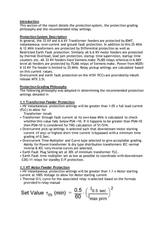
  • 1. Introduction This section of the report details the protection system, the protection grading philosophy and the recommended relay settings. Protection System Description In general, the 33 kV and 6.6 kV Transformer feeders are protected by IDMT, instantaneous over current and ground fault protection. In addition to this 25 MVA & 12 MVA transformers are protected by Differential protection as well as Restricted Earth Fault protection. Similarly all 6.6 KV motor feeders are protected by thermal Overload, load jam protection, startup time supervision, startup time counters etc. All 33 KV feeders have Siemens make 7SJ85 relays whereas in 6.6KV level all feeders are protected by 7SJ66 relays of Siemens make. Power from MSDS- II 33 KV Tie feeder is limited to 25 MVA. Relay pickup settings are calculated based on this current values. Overcurrent and earth fault protection on the 415V PCCs are provided by inbuilt release MTX 3.5i. Protection Grading Philosophy The following philosophy was adopted in determining the recommended protection settings detailed in 1.1 Transformer Feeder Protection • HV instantaneous protection settings will be greater than 1.05 x full load current (FLC) to allow for Transformer inrush • Transformer through fault current at its own base MVA is calculated to check whether this value falls below PSM =10. If it happens to be greater than PSM=10 then PSM=10 is considered for TMS calculation of 51/51N. • Overcurrent pick-up settings is selected such that downstream motor starting current (if any) or highest short time current is bypassed with a minimum time grading of 0.3sec. • Overcurrent Time Multiplier and Curve type selected to give acceptable grading. Mainly for Power transformer & dry type distribution transformers IEC normal inverse & IEC very inverse curves are selected. • Earth Fault Plug Setting set at 30% of minimum transformer FLC. • Earth Fault time multiplier set as low as possible to coordinate with downstream CDG-11 relays for standby E/F protection. 1.1 HT Motor Feeder Protection • HV instantaneous protection settings will be greater than 1.1 x Motor starting current at 100% Voltage to allow for Motor starting current • Thermal O/L curve for the associated relay is selected based on the formula provided in relay manual
  • 2. • For motor startup time supervision time calculation is done as per following formula as described in the relay manual The delay time indicated for this protection will inherently overlook the startup period of the motors. • Overcurrent Time Multiplier and Curve type selected to give acceptable grading. Mainly for Power transformer & dry type distribution transformers IEC normal inverse & IEC very inverse curves are selected. • Earth Fault Plug Setting set at 30% of minimum transformer FLC. • Earth Fault time multiplier set as low as possible to coordinate with downstream CDG-11 relays for standby E/F protection. 1.2 Feeder Protection • Overcurrent Plug Setting set at approximately 110% of maximum load below cable ampacity & thermal protection to cables • Overcurrent Time Multiplier and curve selected to give acceptable grading • Earth Fault Plug Setting set at 20% of minimum earth fault level 1.3 Transformer Incomer LV Protection Earth Fault Time Setting selected to operate withina maximum duration of 1 second at 50% of the minimum prospective fault level. 1.4 Switchboard Protection All devices are set to clear switchboard busbar faults withinswitchboard limits which are 40 kA for 3 seconds at 33 kV and 31.5 kA for 3 seconds at 6.6 kV. Additionally, for LV switchboards, devices are set to clear switchboard busbar faults withina maximum duration of 1s. 1.5 Protection Co-ordination The assessment of the overcurrent and earth fault protection co-ordination is discussed below. The time-current characteristic diagrams are included at the end of this section. The protection coordination assessment is based on the fault levels reported in Reference 33 and included in Appendix A of this report. Maximum fault levels are based on all four main generators plus both grid infeeds supplying peak load. Minimum fault levels are based on one gas turbine generator supplying minimum load.
  • 3. Discrimination on the emergency system when fed by the emergency diesel generator is also considered. The discussion of the protection co-ordination refers to the Time Current Co- ordination (TCC) Curves included at the end of the Report text. The current (Ampere) labels displayed on the TCC Curves represent the pickup current for relays and the full load current for transformers. The TCC curves also show the IEC thermal and dynamic damage points along with the transformer inrush current, which are all marked as ‘×’ on the curves. FM IGBT transformer feeders (F-1- F-7): As per HTC input frequent overloading of 175 % for 60 sec will occur. Recommended curve is IEC long inverse curve. Transformer damage curve and inrush currents are considered as per attached Annexure-A (Transformer protection curve) To limit the instantaneous phase o/c pickup during transformer inrush 2nd harmonic & 5th harmonic blocking will be enabled in the relay. IDMT Phase o/c pickup is set at 120% of Transformer F.L.C.