LOGIC GATES VIDEO LECTURE IN HINDI|OR GATE,AND GATE &NOT GATE|LOGIC DIAGRAM &TRUTH TABLE OF GATES
•
0 likes•190 views

https://youtu.be/4Tb2GbE1R-I YOUTUBE LINK #Logic_gates #OR_AND_NOT_GATE #UNIVERSAL_GATES #LOGIC_GATES_TRUTH_TABLE #LOGICGATESNEETPHYSICSKOTA #BASIC_ELECTRONICS #BASICS_ELECTRICAL_ELECTRONICS_ENGINEERING

Recommended
More Related Content
What's hot
What's hot (20)
Similar to LOGIC GATES VIDEO LECTURE IN HINDI|OR GATE,AND GATE &NOT GATE|LOGIC DIAGRAM &TRUTH TABLE OF GATES
Similar to LOGIC GATES VIDEO LECTURE IN HINDI|OR GATE,AND GATE &NOT GATE|LOGIC DIAGRAM &TRUTH TABLE OF GATES (20)
More from Prasant Kumar
More from Prasant Kumar (20)
Recently uploaded
Recently uploaded (20)
LOGIC GATES VIDEO LECTURE IN HINDI|OR GATE,AND GATE &NOT GATE|LOGIC DIAGRAM &TRUTH TABLE OF GATES
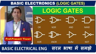
- 1. LOGIC GATES Prof.Prasant Tiwari सरल भाषा में समझेBASIC ELECTRICAL ENG
- 2. LOGIC GATES Logic gates are the basic building blocks of any digital system. It is an electronic circuit having one or more than one input and only one output. The relationship between the input and the output is based on a certain logic. Based on this, logic gates are named as AND gate, OR gate, NOT gate etc.
- 3. It performs the operation of inversion or complementation. That is why it is also known as invertor. It changes a logic level to its opposite level. i.e.it changes 1 to 0 and 0 to 1. NOT GATES
- 4. AND GATE The AND gate has two inputs marked as A and B and output as Y. The AND gate represents the Boolean equation Y = A.B From the above circuit it is clear that AND gates give an output only when both the switches A and B are closed. It means that the both A & B are at 1, the output will also at 1. For all other combinations of the values A and B output is zero
- 5. OR GATE The OR gate has two inputs marked as A and B and output as Y. Now A ,B and Y can have one of the two states either 0 or 1. The OR gate represents the Boolean equation Y=A+B . The OR gate has output 1 and either A or B or both A & B are at logic 1. Above circuit shows that the lamp will light up when either switch A and B or both A & B are closed. The output will be zero if and only if both the inputs or at logic zero. It means that lamp remain off when only when both the switches A and B are open.
- 6. PLZ VISIT YPUTUBE CHANNEL FOR VIDEO LINK IS GIVEN IN DESCRIPTION BOX