
Recommended
Recommended
More Related Content
What's hot
What's hot (20)
Similar to DIGITAL SYSTEM DESIGN
Similar to DIGITAL SYSTEM DESIGN (20)
More from Prakash Rao
Recently uploaded
Recently uploaded (20)
DIGITAL SYSTEM DESIGN
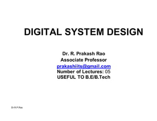
- 1. Dr.R.P.Rao DIGITAL SYSTEM DESIGN Dr. R. Prakash Rao Associate Professor prakashiits@gmail.com Number of Lectures: 05 USEFUL TO B.E/B.Tech
- 2. Syllabus Dr.R.P.Rao Introduction; Boolean algebra; operations NOT, AND, OR; truth tables; Boolean identities and theorems; Boolean functions; Logic gates; combinational logic systems; analysis of combinational systems; duality Karnaugh maps; Boolean simplification using K-maps; sum-of-products and product-of-sums forms; incompletely- specified Boolean functions; implementation using logic gates; Universal logic gates; simple implementation method; formal method for NAND implementation; formal method for NOR implementation
- 3. Syllabus Dr.R.P.Rao Combinational logic systems; static and dynamic hazards; origin of static hazards in 2-level NAND systems; origin of dynamic hazards; design of hazard-free NAND and NOR systems, Other types of logic gate: EXOR gates; MSI combinational functions: 7-segment, decoders and encoders, multiplexers; programmable logic Sequential logic systems; RS Flip-flops; D-latch; edge- triggered flip-flops; edge-triggered D-type flip-flop, Asynchronous counters; synchronous counters; shift registers; design of synchronous counters using edge- triggered D-type flip-flops
- 4. Syllabus Dr.R.P.Rao Edge-triggered JK flip-flops; asynchronous counters, shift registers,Types of logic gate: TTL + variants, CMOS, ECL; comparisons of gate types; decoupling.
- 5. Analogue vs Digital Dr.R.P.Rao Analogue signals represent physical quantities by a simple proportional relationship The precision of analogue signals is limited by noise/drift relative to the maximum signal and by non-linearity Digital signals use numbers to represent physical quantities There is in principle no limit to the precision of digital signals Digital systems use binary numbers, rather than decimal, to define digital values
- 6. Binary Codes Dr.R.P.Rao Digital electronics uses binary values: 0 or 1 These are represented in digital circuits by voltages or currents, for example: Logic 0: 0 V 0.8 V Logic 1: 2.0 V 5.0 V Binary digits are called bits Bits are normally processed in groups: a group of binary digits is called a binary word, or more simply, a word
- 7. Binary Codes Dr.R.P.Rao Digital words can be transmitted / processed in serial or parallel form: 5-bit word - serial data 11010: 1 1 0 1 0 5-bit word - parallel data 11010: 1 1 0 1 0
- 8. Binary Codes Dr.R.P.Rao Words represent information by the use of binary codes Examples of binary codes: Natural binary code Signed binary code Floating-point codes Gray code Alpha-numeric codes Extra bits can be added to any of these codes to make them error-detecting or error-correcting
- 9. Natural Binary Code Dr.R.P.Rao An n-bit word: dn-1, … d2, d1, d0 where dr are the individual bits (value 0 or 1), represents the positive integer value: 2n-1dn-1 + … + 22d2 + 21d1 + 20d0 So the 6-bit natural binary word 010110 represents the integer value: 25.0 + 24.1 + 23.0 + 22.1 + 21.1 + 20.0 = 16 + 4 + 2 = 22
- 10. Natural Binary Code Dr.R.P.Rao Natural binary is the most efficient code in the sense that is uses the minimum number of bits It is easy to perform arithmetic operations on natural binary code 8-bit natural binary code represents: 0 255 16-bit natural binary code represents: 0 65535 32-bit natural binary code represents: 0 4295M In general an n-bit natural binary code represents: 0 (2n-1)
- 11. 4-Bit Natural Binary Code Dr.R.P.Rao Decimal Natural binary Decimal Natural binary 8 1000 9 1001 10 1010 11 1011 12 1100 13 1101 14 1110 15 1111 0 0000 1 0001 2 0010 3 0011 4 0100 5 0101 6 0110 7 0111
- 12. Signed Binary Code Dr.R.P.Rao In many applications it is necessary to represent negative as well as positive numbers For example: audio signals, bank account The most common (and most satisfactory) representation for signed integers is 2s-complement binary The operations required to add or subtract 2s-complement numbers are identical to those for natural binary
- 13. 2s-Complement Binary Code Dr.R.P.Rao To obtain the 2s-complement representation of a negative number: 1. Obtain natural binary representation of its magnitude 2. Complement (0 1, 1 0) 3. Add 1 Example: -5 Add 1 111011 -5 Natural binary 000101 5 Complement 111010
- 14. 2s-Complement Binary Code Dr.R.P.Rao The sign of a 2s-complement number is determined by the most-significant (left-most) bit 8-bit signed binary code represents: -128 +127 16-bit signed binary code represents: -32768 +32767 32-bit signed binary code represents: -2147M +2147M n-bit signed binary code represents: -2n-1 +(2n-1-1)
- 15. Hamming Distance Dr.R.P.Rao The Hamming distance between two code words is the number of bits that must change to convert one code word into the other 1 0 1 1 0 0 1 1 1 0 0 1 1 0 1 1 Hamming distance = 2 The minimum distance of a code is the minimum Hamming distance between any pair of words belonging to the code An n-distance code is a code sequence where the Hamming distance between consecutive code words is n
- 16. Gray Code Dr.R.P.Rao Digital position transducer coded using natural binary: Infra-red detectors (4) Infra-red emitters (4) Clear 8 4 2 1 Position = 1001 (binary) = 8 + 1 (decimal) = 9
- 17. Gray Code Dr.R.P.Rao This should work in principle, but fails in practice because the bits do not change simultaneously: 8 0 0 1 1 1 4 1 0 0 0 0 2 1 1 1 1 0 1 1 1 1 0 0 Indicated position: 7 3 11 10 8 Thus spurious positions of 3, 11, and 10 are generated between 7 and 8 This problem is overcome by using Gray code
- 18. 4-Bit Gray Code Dr.R.P.Rao Decimal Gray code Decimal Gray code 8 1100 9 1101 10 1111 11 1110 12 1010 13 1011 14 1001 15 1000 0 0000 1 0001 2 0011 3 0010 4 0110 5 0111 6 0101 7 0100
- 19. Gray Code Dr.R.P.Rao Digital position transducer coded using Gray code (unit- distant): Infra-red detectors (4) Infra-red emitters (4) Clear Position = 1101 = 9
- 20. Alpha-Numeric Codes Dr.R.P.Rao ASCII (American Standard Code for Information Interchange) is a 7-bit code representing alpha-numeric characters The code includes control characters, punctuation, symbols, digits, letters: 0000000: nul 0001101: cr 0011011: esc 0101011: + 0110000: 0 0111001: 9 1000001: A 1011010: Z 1100001: a 1111010: z 1111111: del
- 21. Error-Detecting Codes Dr.R.P.Rao An extra bit added to each binary word allows single errors to be detected (but not corrected) This bit is called the parity bit and is chosen to make the total number of 1s even (even parity) or odd (odd parity) A single error will lead to the number of 1s changing from odd to even, or from even to odd; the change in parity then indicates an error Parity codes are redundant, and have a minimum Hamming distance of 2
- 22. Error-Detecting Codes Dr.R.P.Rao Invalid codeword (I bit error) Error-detecting codes have a minimum Hamming distance of 2: Valid codeword Valid codeword 1 bit 2 bits
- 23. Natural Binary Code / Even Parity Dr.R.P.Rao Decimal Even Parity Decimal Even Parity 8 11000 9 01001 10 01010 11 11011 12 01100 13 11101 14 11110 15 01111 0 00000 1 10001 2 10010 3 00011 4 10100 5 00101 6 00110 7 10111
- 24. Natural Binary Code / Odd Parity Dr.R.P.Rao Decimal Odd Parity Decimal Odd Parity 8 01000 9 11001 10 11010 11 01011 12 11100 13 01101 14 01110 15 11111 0 10000 1 00001 2 00010 3 10011 4 00100 5 10101 6 10110 7 00111
- 25. Dr.R.P.Rao Error-detecting codes are of little value in 1-way communications systems (cannot be corrected) If a single bit error occurs in a code with a minimum distance of 3 or greater then the error can be both detected and corrected This is because the single error generates a new word which is distance 1 from the original word; it is still distance 2 from any other code word Sometimes called “forward error correction”
- 26. Dr.R.P.Rao Invalid codeword (I bit error) Error-correcting code with minimum Hamming distance of 3: Valid codeword Valid codeword 1 bit 3 bits
- 27. Dr.R.P.Rao Invalid codeword (2 bits error) Error-correcting code with minimum Hamming distance of 5: Valid codeword Valid codeword 1 bit 5 bits
- 28. Dr.R.P.Rao Decimal E-C code Decimal E-C code Right-most 3 bits are natural binary, left-most 3 bits are error-correction Example: 110110 is not a valid codeword Nearest valid codeword is 110010 (decimal 2) 4 101100 5 110101 6 011110 7 000111 0 000000 1 011001 2 110010 3 101011
- 29. Boolean Algebra Dr.R.P.Rao Boolean algebra is an algebra of 2-state variables Boolean variables can have the values 0 or 1 Boolean Algebra is used to describe digital systems where the binary signals have 2 values There are three fundamental operations in Boolean algebra: NOT, AND, OR These are defined by the use of truth tables
- 30. Boolean Algebra Dr.R.P.Rao NOT A or A or A A AND B or A.B A A 0 1 1 0 A B A.B 0 0 0 0 1 0 1 0 0 1 1 1
- 31. Boolean Algebra Dr.R.P.Rao A OR B or A B There are other Boolean operators such as (exclusive OR) and (implies), but these can be written in terms of the operators NOT, AND, OR: A BA.B A.B A B A+B 0 0 0 0 1 1 1 0 1 1 1 1
- 32. Boolean Algebra Dr.R.P.Rao The operations of AND and OR obey the usual laws of algebra: Associative laws: A.(B.C) (A.B).C A (B C) (A B) C Commutative laws: A.B B.A A B B A A.(B C) A.BA.C Distributive laws: A (B.C) (AB).(A C)
- 33. Proof: A.(B+C) ≡ A.B + A.C Dr.R.P.Rao A B C B+C A.(B+C) A.B A.C A.B+A.C 0 0 0 0 0 0 0 0 0 0 1 1 0 0 0 0 0 1 0 1 0 0 0 0 0 1 1 1 0 0 0 0 1 0 0 0 0 0 0 0 1 0 1 1 1 0 1 1 1 1 0 1 1 1 0 1 1 1 1 1 1 1 1 1 A.(B+C) = A.B + A.C for all combinations of the variables: thus A.(B+C) A.B + A.C
- 34. Boolean Identities Dr.R.P.Rao A number of other identities follow from the definitions of NOT, AND, OR: A 0 A A.0 0 A 1 1 A.1 A A A A A.A A A A 1 A.A 0 Theorems of DeMorgan: A B A B A.B
- 35. Proof of DeMorgan’s Theorems Dr.R.P.Rao A B A.B A.B A B A B 0 0 0 1 1 1 1 0 1 0 1 1 0 1 1 0 0 1 0 1 1 1 1 1 0 0 0 0 A B A+B A B A B A.B 0 0 0 1 1 1 1 0 1 1 0 1 0 0 1 0 1 0 0 1 0 1 1 1 0 0 0 0
- 36. Boolean Functions Dr.R.P.Rao There is no unique form for a Boolean algebraic expression. Consider the function: F A.(B C B.C)A.B.(C D) By "multiplying out" the brackets and using DeMorgan’s Theorems: F A.B A.B.C A.B.C.D This is the sum-of-products standard form. An alternative standard form is the product-of-sums: F (A B).(A B D).(AB C)
- 37. Algebraic Manipulation of Boolean Functions Dr.R.P.Rao Some simplification can be achieved by multiplying out brackets and using Boolean identities (including DeMorgan’s theorems): F A C.D A.B ((C.D) A) A C.D (C D A) A C.D A.B C.D.A A.(1 B) C.D.(1A) A.1 C.D.1 A C.D This is the simplest sum-of-products form for F
- 38. Algebraic Manipulation of Boolean Functions Dr.R.P.Rao This process does not guarantee to produce the simplest sum-of-products form Consider the function: F X.Y X.Z Y.Z There is no obvious way of simplifying this function algebraically. Nevertheless, the simplest form of the function is: F X.Y X.Z Graphical methods for obtaining the simplest form will be discussed later
- 39. Switch Logic Dr.R.P.Rao F A.B.C F A B C F A.B.(C D)
- 40. Logic Gates Dr.R.P.Rao Binary signals are processed in electronic digital systems by logic gates: A B C AND A A A.B.C NOT A A B C NAND A A.B.C B A C OR B C B C NOR A B C
- 43. Logic Signals Dr.R.P.Rao Binary values are normally represented by voltages. For example in HCT logic: Logic 1 Logic 0 Noise immunity: Outputs: 5.0 V 2.4 V 0.55 V 0.0 V Inputs: 5.0 V 2.0 V 0.8 V 0.0 V Logic 0 = 0.25 V Logic 1 = 0.4 V
- 44. Combinational Logic Systems Dr.R.P.Rao Systems of logic gates where there is no feedback are called combinational logic systems Combinational logic systems have the property that the output or outputs depend only on the present state of the inputs Combinational systems can therefore be specified by a Boolean expression. Logic systems with feedback have the property of memory and cannot be specified by a single Boolean expression.
- 45. Combinational Logic Systems Dr.R.P.Rao A B C D B.C C D A A.B.(C D) F B C B.C A.(B C B.C) This combinational system implements the Boolean function: F A.(B C B.C)A.B.(C D)
- 46. Duality Dr.R.P.Rao A Boolean equation remains valid when converted to its dual by changing all variables and constants to their inverses, and replacing AND by OR, and OR by AND For example if: F A.(B C B.C)A.B.(C D) or: F {A.(B C {B.C})} {A.B.(C D)} then: F {A (B.C.{B C})}.{AB (C.D)} or: F {A B.C.{B C}}.{AB C.D}
- 47. Karnaugh Maps Dr.R.P.Rao Karnaugh maps (or K-maps) are graphical representations of Boolean functions and are used to simplify Boolean expressions A K-map has one square for each combination of values of the variables 1-variable K-Map: F A A=0 A=1 0 1
- 48. Karnaugh Maps Dr.R.P.Rao 2-variable K-map: B=0 B=1 F A B A=0 A=1 3-variable K-map: F C.(A B) A=0 A=1 B=0 B=1 B=0 C=0 C=1 1 1 0 1 0 1 0 0 0 1 0 1
- 49. Karnaugh Maps Dr.R.P.Rao 4-variable K-map: C=0 C=1 F A B.C.D A=0 A=1 B=0 B=1 B=0 D=0 D=1 D=0 Note that adjacent columns and adjacent rows are unit- distant 0 0 0 0 0 0 1 0 1 1 1 1 1 1 1 1
- 50. Karnaugh Maps Dr.R.P.Rao 1 1 0 0 0 0 0 0 0 0 0 0 1 1 0 0 0 0 0 0 1 0 0 1 0 0 0 0 0 0 0 0 1 0 0 1 0 0 0 0 0 0 0 0 1 0 0 1 A complication of 3- and 4-variable maps is that they must be regarded as being wrapped around on themselves: F B.C F A.B .D F B .D
- 51. Boolean Simplification Dr.R.P.Rao The preferred method for simplifying Boolean expressions in 4 variables or less uses K-maps The first stage is to obtain the sum-of-products standard form using algebraic manipulation The function is then represented in K-map form Finally the simplest form for the expression is extracted from the K-map To obtain the simplest sum-of-products form the K-map is inspected for the largest groups first; then for progressively smaller groups
- 52. Boolean Simplification Dr.R.P.Rao F A.B A.B.C A.B.C.D C=0 C=1 A=0 B=0 B=1 D=0 D=1 D=0 Groups of 16: none Groups of 8: A Groups of 4: none A=1 Groups of 2: B .C.D B=0 Groups of 1: none Simplest sum-of-products form for F is: F A B.C.D 1 1 1 1 1 1 1 1 1 0 0 0 0 0 0 0
- 53. Boolean Implementation Dr.R.P.Rao A B.C.D The simplest sum-of-products form for F: F A B.C.D can now be implemented using a combination of AND, OR and NOT gates: A B F C D
- 54. Boolean Simplification Dr.R.P.Rao To obtain a function F in simplest product-of-sums form, the first step is to obtain F in simplest sum-of-products form: C=0 C=1 A=0 A=1 B=0 B=1 B=0 D=0 D=1 D=0 Simplest sum-of-products form for F is: F A.B A.C 1 1 1 1 1 1 1 1 1 0 0 0 0 0 0 0
- 55. Boolean Simplification Dr.R.P.Rao F A.B A.D A.C Now use duality to obtain F in simplest product-of-sums form: F (A.B) (A.D) (A.C) F (A B).(A D).(A C) OR invert and use DeMorgan’s Theorems twice to obtain F in simplest product-of-sums form: F (A.B) (A.D) (A.C) (A.B) . (A.D) . (A.C) F (A B).(A D).(A C)
- 56. Boolean Implementation Dr.R.P.Rao A B A C A D F (A B).(A D).(A C) A B C F D
- 57. Incompletely-Specified Functions Dr.R.P.Rao It often happens that the value of a function is not specified for some combinations of the input variables In other words the value of the function is "don't-care" and this is represented by X K-maps can be used to simplify incompletely-specified functions, with the don't-care conditions being assigned either 0 or 1 Incompletely-specified functions cannot be defined by a Boolean expression; instead a truth table is used
- 58. Incompletely-Specified Functions Dr.R.P.Rao A B C D F 0 0 0 0 0 0 0 0 1 0 0 0 1 0 0 0 0 1 1 1 0 1 0 0 1 0 1 0 1 1 0 1 1 0 1 0 1 1 1 X A B C D F 1 0 0 0 0 1 0 0 1 0 1 0 1 0 X 1 0 1 1 X 1 1 0 0 1 1 1 0 1 1 1 1 1 0 1 1 1 1 1 1 Function F defined by a truth table:
- 59. Incompletely-Specified Functions Dr.R.P.Rao Each row of the truth table corresponds to one square of the K-map: C=0 C=1 A=0 A=1 B=0 B=1 B=0 D=0 D=1 D=0 Simplest sum-of-products form for F is: F B C.D 0 0 1 0 1 1 X 1 1 1 1 1 0 0 X X
- 60. Incompletely-Specified Functions Dr.R.P.Rao 0 00 XX 1111 1X11 010 C=0 C=1 A=0 A=1 B=0 B=1 B=0 D=0 D=1 D=0 Simplest sum-of-products form for F is: F B.C B.D Simplest product -of-sums form for F is: F (B C).(B D)
- 61. Boolean Implementation Dr.R.P.Rao C.D A Boolean function can be implemented by first obtaining the simplest sum-of-products form: F B C.D The overall OR function is then implemented using an OR gate, each of the terms is implemented using AND gates, and NOT gates are used where required to invert the inputs: B B F C D
- 62. Boolean Implementation Dr.R.P.Rao Alternatively implementation can start from the simplest product-of-sums form: F (B C).(B D) The overall AND function is then implemented using an AND gate, each of the factors is implemented using OR gates, and NOT gates are used where required to invert the inputs: B C F D B+C B+D
- 63. Universal Logic Gates Dr.R.P.Rao NAND gates: NOT A (A.A) A NOT A AND A B A OR B (A.1) (A.B) (A.B) A A.B A B 1
- 64. Universal Logic Gates Dr.R.P.Rao NOR gates: NOT A (A A) A NOT A AND A (A 0) A B OR A B (A B) A.B (A B) A B 0
- 65. Implementation in NAND Dr.R.P.Rao 1. Obtain the function in simplest sum-of-products form: F A.B C.D.E ... 2. Invert the function twice (thus leaving it unchanged): F A.B C.D.E ... 3. Use DeMorgan’s theorem on lower inversion: F (A.B ).(C.D.E).... 4. The function can now be implemented using only NAND gates
- 66. Implementation in NAND Dr.R.P.Rao Example: F A A B.C.D B.C.D A .(B.C.D) A .(B.C.D) A B C D A F B.C.D
- 67. Design Example Dr.R.P.Rao The days of the week are represented by a 3-bit binary code: The code 000 will never occur Design a NAND system to give 1 for the work-days, and 0 for the rest-days P Q R Sunday 0 0 1 Monday 0 1 0 Tuesday 0 1 1 Wednesday 1 0 0 Thursday 1 0 1 Friday 1 1 0 Saturday 1 1 1
- 68. Design Example Dr.R.P.Rao The first stage is to construct a K-map: P=0 P=1 Q=0 Q=1 Q=0 R=0 R=1 Note the use of X for the unused code: 000 The simplest sum-of-products form is: F R P.Q P.Q X 0 1 1 1 0 1 1 Unused Sunday Monday Tuesday Friday Saturday Wednesday Thursday
- 69. Design Example Dr.R.P.Rao F R P.Q P.Q R . (P.Q) . (P.Q) R. (P.Q) . (P.Q) P F Q R P P.Q Q P.Q
- 70. Design Example Dr.R.P.Rao The numbers 0 to 15 are represented by the 4-bit natural binary code ABCD (A is the most-significant bit, D the least- significant A function F is required to have a value of 1 for prime numbers, and to have a value of 0 for composite (non- prime) numbers. For the purpose of this design example the numbers 0 and 1 will be taken to be composite. Design a combinational logic system consisting of NAND gates to implement the function F of the variables A, B, C and D.
- 71. Design Example Dr.R.P.Rao C=0 C=1 A=0 A=1 B=0 B=1 B=0 D=0 D=1 0 F B.C.D A.B.C B.C.DA.B.D The 1s on the K-map can be grouped in a different way: F B.C.D A.B.C B.C.DA.C.D D= 0 0 1 1 0 1 1 0 0 1 0 0 0 0 1 0 0 1 3 2 4 5 7 6 12 13 15 14 8 9 11 10
- 72. Design Example Dr.R.P.Rao F B.C.D A.B.C B.C.D A.B.D B.C.D A.B.C B.C.D A.B.D (B.C.D) .(A.B.C) . (B.C.D) . (A.B.D) B A F C D B.C.D A.B.C B.C.D A.B.D
- 73. Implementation in NOR Dr.R.P.Rao 1. Obtain the function in simplest product-of-sums form: F (A B).(B C D).... 2. Invert the function twice (thus leaving it unchanged): F (A B).(B C D).... 3. Use DeMorgan’s theorem on lower inversion: F (A B) (B C D) ... 4. The function can now be implemented using only NOR gates
- 74. Implementation in NOR Dr.R.P.Rao (A B) (A C) (A D) Example: F (A (A B).(A B).(A D).(A C) D).(A C) (A B) (A D) (A C) A B C F D
- 75. Design Example Dr.R.P.Rao The days of the week are represented by a 3-bit binary code: The code 000 will never occur Design a NOR system to give 1 for the work-days, and 0 for the rest-days P Q R Sunday 0 0 1 Monday 0 1 0 Tuesday 0 1 1 Wednesday 1 0 0 Thursday 1 0 1 Friday 1 1 0 Saturday 1 1 1
- 76. Design Example Dr.R.P.Rao The first stage is to construct a K-map: P=0 P=1 Q=0 Q=1 Q=0 R=0 R=1 The simplest sum-of-products form for F is: F P.Q P.Q.R The simplest product-of-sums form for F is: F (P Q).(P Q R) X 0 1 1 1 0 1 1 Unused Sunday Monday Tuesday Friday Saturday Wednesday Thursday
- 77. Design Example Dr.R.P.Rao F (P (P Q).(P Q).(P Q R) Q R) (P P Q R Q) (P Q R) F (P Q) P Q (P Q R) R
- 78. Hazards in Combinational Logic Systems Dr.R.P.Rao B A hazard is a transient change that occurs in a logic system following a change in an input Hazards are the result of gate delays A C The output C is given by: C A B A A 1 Thus the output should stay at logic 1, and be independent of the input.
- 79. Hazards in Combinational Logic Systems Dr.R.P.Rao In fact an output pulse occurs following the 10 input transition: A B A C=A+B Delay in NOT Delay in NOT Hazard exists for a time equal to the gate delay (typically a few ns)
- 80. Hazards in Combinational Logic Systems Dr.R.P.Rao There are two types of hazard: static hazards and dynamic hazards Static hazard: Dynamic hazard: Whether hazards are significant depends on the application Hazards are always a problem if they occur in logic providing the input to a system with memory
- 81. Hazards in NAND Systems Dr.R.P.Rao Output gate 2-level NAND system: Input gates Suppose that an input Q changes: no input gate can have both Q and Q for inputs because: Q.Q.... 0 1
- 82. Hazards in NAND Systems Dr.R.P.Rao Case 1: (potential dynamic hazard) Input gate 1 Input gate 2 Output No Hazard
- 83. Hazards in NAND Systems Dr.R.P.Rao Case 2: (potential static hazard) Input gate 1 Input gate 2 Output No Hazard
- 84. Hazards in NAND Systems Dr.R.P.Rao Case 3: (potential static hazard) Input gate 1 Input gate 2 Output Dynamic hazards do not occur in 2-level NAND systems Static hazards can occur if one input gate changes from 01 whilst another input gate changes from 10
- 85. Properties of K-maps Dr.R.P.Rao Moving one square horizontally or vertically corresponds to changing a single input variable Each input gate corresponds to a group of 1s on the K-map: moving in or out of a group causes the corresponding input gate to change state If 2 groups of 1s on the K-map are adjacent and non- overlapping (horizontally or vertically) then changing a single input variable can move out of one group and into the other This is the condition for a static hazard
- 86. Example of a Static Hazard Dr.R.P.Rao F A.C B.C.DA.B.C C=0 C=1 A=0 A=1 B=0 B=1 B=0 D=0 D=1 D=0 F A.C B.C.D A.B.C A static hazard may occur if the inputs change from A=0, B=1, C=0, D=1 to A=0, B=1, C=1, D=1 1 1 0 0 1 1 1 0 0 0 1 1 0 0 0 0
- 87. Example of a Static Hazard Dr.R.P.Rao F A.C A.C B.C.D B.C.D A.B.C A.B.C A.C .(B.C.D) .(A.B.C) Q1.Q2 .Q3 ABCD ABCD 0101 0111 Q1 (A.C) 0 1 Q2 Q3 (B.C.D) 1 0 (A.B.C) 1 1 This is condition for a static hazard
- 88. Eliminating Static Hazards Dr.R.P.Rao Static hazards are eliminated by including extra groups which overlap the offending transitions: C=0 C=1 A=0 A=1 B=0 B=1 B=0 D=0 D=1 D=0 F A.C B.C.DA.B.C A.B.D The input gate corresponding to the new group remains at 0 throughout the transition 0000 1100 11 01 0011
- 89. Eliminating Static Hazards Dr.R.P.Rao F A.C A.C B.C.D B.C.D A.B.C A.B.C A.B.D A.B.D A.C .(B.C.D) .(A.B.C) .(A.B.D) Q1.Q2.Q3 .Q4 ABCD ABCD 0101 0111 Q1 (A.C) 0 1 Q2 Q3 Q4 (B.C.D) 1 0 (A.B.C) 1 1 (A.B.D) 0 0 Static hazard has been eliminated
- 90. Design Example Dr.R.P.Rao 0 0 0 0 Implement the function: F A.D B.C B.D in hazard-free form using NAND gates C=0 C=1 A=0 A=1 B=0 B=1 B=0 D=0 D=1 D=0 Simplest sum-of-products form: F A.D B.C B.D 1 0 1 1 1 1 1 1 0 1 1 0
- 91. Design Example Dr.R.P.Rao Include an extra group to overlap the border between the adjacent groups: C=0 C=1 A=0 A=1 B=0 B=1 B=0 D=0 D=1 D=0 Hazard-free sum-of-products form: F A.D B.C B.DA.B 0 0 0 0 1 0 1 1 1 1 1 1 0 1 1 0
- 92. Design Example Dr.R.P.Rao F A.D A.D B.C B.C B.D B.D A.B A.B (A.D) .(B.C) .(B.D) .(A.B) A B C F D
- 93. Hazards in NOR Systems Dr.R.P.Rao Dynamic hazards do not occur in 2-level NOR systems Static hazards can occur if one input gate changes from 01 whilst another input gate changes from 10 If 2 groups of 0s on the K-map are adjacent and non- overlapping (horizontally or vertically) then changing a single input variable can move out of one group and into the other This is the condition for a static hazard
- 94. Example of a Static Hazard Dr.R.P.Rao 0110 1111 0011 0011 F A.B A.D A.C B.C C.D C=0 C=1 A=0 A=1 B=0 B=1 B=0 D=0 D=1 D=0 F A.C A.B.D A static hazard may occur if the inputs change from A=1, B=0, C=1, D=0 to A=0, B=0, C=1, D=0
- 95. Example of a Static Hazard Dr.R.P.Rao F (A.C) (A.B.D) F (A C).(A (A C).(A B D) B D) (A C) (A B D) Q1Q2 Q1 (A C) ABCD ABCD 1010 0010 0 1 Q2 (A B D) 1 0 This is condition for a static hazard
- 96. Eliminating Static Hazards Dr.R.P.Rao 0110 1111 0011 0011 Static hazards are eliminated by including extra groups which overlap the offending transitions: C=0 C=1 A=0 A=1 B=0 B=1 B=0 D=0 D=1 D=0 F A.C A.B.D B.C.D The input gate corresponding to the new group remains at 1 throughout the transition
- 97. Eliminating Static Hazards Dr.R.P.Rao F (A.C) (A.B.D) (B.C.D) F (A C).(A (A C).(A B D).(B C B D).(B C D) D) (A C) (A B D) (B C D) Q1 Q2 Q3 ABCD ABCD 1010 0010 Q1 (A C) 0 1 Q2 (A B D) 1 0 Q3 (B C D) 1 1 Static hazard has been eliminated
- 98. Design Example Dr.R.P.Rao Implement the function: F A.C B.C A.B.C in hazard-free form using NOR gates A=0 A=1 B=0 B=1 B=0 C=0 C=1 Simplest sum-of-products form for F : F A.C A.B 00 11 01 01
- 99. Design Example Dr.R.P.Rao Include an extra group to overlap the border between the adjacent groups: A=0 A=1 B=0 B=1 B=0 C=0 C=1 Hazard-free sum-of-products form: F A.C A.B B.C 1 0 1 0 1 1 0 0
- 100. Design Example Dr.R.P.Rao F (A.C) (A.B) (B.C) F (A C).(A (A C).(A B).(B C) B).(B C) (A C) (A B) (B C) A F B C
- 101. Dynamic Hazards Dr.R.P.Rao E G F D There must be at least three paths between the input and output to give the minimum of three transitions that constitute a dynamic hazard: A C B H D C E A.C F B.D B.C G E F A.C B.C H D.G C.(A.C B.C) B.C
- 102. Dynamic Hazards Dr.R.P.Rao D C Let A=1 B=1 E A.C F B.D B.C G E F A.C B.C H D.G C D E F G H C.(A.C B.C) B.C
- 103. Exclusive-OR Gates Dr.R.P.Rao A XOR B or AB This function is similar to the normal (inclusive) OR function except for the case A=1, B=1 Electrical symbol: Identities: A B A B B A AB (A B) C A (B C) A B A+B 0 0 0 0 1 1 1 0 1 1 1 0
- 104. Exclusive-OR Gates Dr.R.P.Rao Exclusive-OR functions of more than 2 variables can be generated by using several 2-input gates: A B ABC C A B ABCD C D Operating between several variables the exclusive-OR function is 1 if an odd number of the input variables are 1
- 105. Exclusive-OR Gates Dr.R.P.Rao A=0 A=1 B=0 B=1 0 1 1 0 A=0 A=1 B=0 B=1 C=0 C=1 AB C=0 C=1 B=0 ABC A=0 A=1 B=0 B=1 B=0 D=0 D=1 D=0 ABCD 0 1 1 0 0 1 1 0 0 1 0 1 1 0 1 0 0 1 0 1 1 0 1 0
- 107. 7-Segment Decoder Dr.R.P.Rao To reduce the number of connections the cathodes or anodes of the LEDs are connected in common: Common anode Common cathode a b c d e f g common a b c d e f g common
- 108. 7-Segment Decoder Dr.R.P.Rao Value Binary 7-Segment Display D C B A a b c d e f g 0 0 0 0 0 1 1 1 1 1 1 0 1 0 0 0 1 0 1 1 0 0 0 0 2 0 0 1 0 1 1 0 1 1 0 1 3 0 0 1 1 1 1 1 1 0 0 1 4 0 1 0 0 0 1 1 0 0 1 1 5 0 1 0 1 1 0 1 1 0 1 1 6 0 1 1 0 1 0 1 1 1 1 1 7 0 1 1 1 1 1 1 0 0 0 0 8 1 0 0 0 1 1 1 1 1 1 1 9 1 0 0 1 1 1 1 1 0 1 1
- 109. 7-Segment Decoder Dr.R.P.Rao Functions a, b, c, d, e, f of the binary code A, B, C, D can now be obtained using a K-map: Function a: C=0 C=1 A=0 A=1 B=0 B=1 B=0 D=0 D=1 D=0 The simplest sum-of-products form for a is: a B D A.C A.C 1 1 X 0 1 X X 1 1 X X 1 0 1 X 1
- 110. 7-Segment Decoder Dr.R.P.Rao Medium-Scale Integration (MSI) devices are available which implement these Boolean functions and also provide current drive: Binary inputs +5V Devices are also available to drive Liquid-Crystal Displays (LCD) and multi-digit displays 74HCT47 200 a b c d e f g A B C D
- 111. Decoders Dr.R.P.Rao A decoder converts the information on n input lines to 2n output lines For any input combination one, and only one, output line is set to logical 1 For example, a 3-to-8 line decoder 74HCT138 Y0 Y1 Y2 Y3 Y4 Y5 Y6 Y7 A B C
- 112. Decoders Dr.R.P.Rao Truth table for a 3-to-8 line decoder: C B A Y0 Y1 Y2 Y3 Y4 Y5 Y6 Y7 0 0 0 1 0 0 0 0 0 0 0 0 0 1 0 1 0 0 0 0 0 0 0 1 0 0 0 1 0 0 0 0 0 0 1 1 0 0 0 1 0 0 0 0 1 0 0 0 0 0 0 1 0 0 0 1 0 1 0 0 0 0 0 1 0 0 1 1 0 0 0 0 0 0 0 1 0 1 1 1 0 0 0 0 0 0 0 1
- 113. Encoders Dr.R.P.Rao Encoders have 2n input lines, n output lines, and perform the opposite operation to decoders If one of the input lines is at logical 1 then the output lines indicate the code for this input For example, an 8-to-3 line encoder 74HCT148 A B C Y0 Y1 Y2 Y3 Y4 Y5 Y6 Y7
- 114. Priority Encoders Dr.R.P.Rao Truth table for an 8-to-3 line priority encoder: Y0 Y1 Y2 Y3 Y4 Y5 Y6 Y7 C B A 0 0 0 0 0 0 0 0 0 0 0 1 0 0 0 0 0 0 0 0 0 0 X 1 0 0 0 0 0 0 0 0 1 X X 1 0 0 0 0 0 0 1 0 X X X 1 0 0 0 0 0 1 1 X X X X 1 0 0 0 1 0 0 X X X X X 1 0 0 1 0 1 X X X X X X 1 0 1 1 0 X X X X X X X 1 1 1 1
- 115. Multiplexers Dr.R.P.Rao A multiplexer (MUX) is a combinational logic device that selects binary information from one of several input lines Data inputs For example, an 8-to-1 line MUX 74HCT152 Select inputs C B A WD0 D1 D2 D3 D4 D5 D6 D7
- 116. Multiplexers Dr.R.P.Rao Truth table for a 1-to-8 line multiplexer: C B A W 0 0 0 D0 0 0 1 D1 0 1 0 D2 0 1 1 D3 1 0 0 D4 1 0 1 D5 1 1 0 D6 1 1 1 D7
- 117. Programmable Logic Dr.R.P.Rao Programmable logic is increasingly being used instead of standard gates Programmable logic often leads to lower cost (both design costs and hardware costs) Types of programmable logic include: PROMs, PALs, GALs and FPGAs The function of programmable logic is determined by the state of “fuses” on the integrated circuit These fuses are programmed in a special-purpose programmer connected to a PC
- 118. Programmable Array Logic Dr.R.P.Rao Inputs: Program- mable AND matrix A B C Fixed OR matrix Outputs: W X Y Z
- 119. HDL Definition File Dr.R.P.Rao PIN 1 = A; Name EX1; Partno EX0000; Date 6/10/98; Rev 01; Designer J.B.Grimbleby; Company University of Reading; Assembly None; Location None; Device p16l8; /* input pins */ PIN 2 = B; PIN 4 = D; /* output pins */ PIN 19 = F; /* equations */ F = !A & (B # C # !B & !C) # A & B & !(C # D); Boolean Operator Symbols: ! NOT & AND # OR PIN 3 = C;
- 120. HDL Documentation File Dr.R.P.Rao Expanded Product Terms: !F => A & !B # A & C # A & D Symbol Table: Pin Variable Pol Name Ext Pin Type Pterms Used Max Pterms Min Level --- -------- --- --- ---- ------ ------ ----- A 1 V - - - B 2 V - - - C 3 V - - - D 4 V - - - F 19 V 3 7 1
- 121. JEDEC Output File Dr.R.P.Rao CUPL(WM) 4.9a Serial# MW-20007187 Device p16l8 Library DLIB-h-39-8 Created Mon Oct 05 19:23:13 1998 Name EX1 Partno EX0000 Revision 01 Date 6/10/98 Designer J.B.Grimbleby Company University of Reading Assembly None Location None *QP20 *QF2048 *G0 *F0 *L00000 11111111111111111111111111111111 *L00032 10011111111111111111111111111111 *L00064 11010111111111111111111111111111 *L00096 11011111011111111111111111111111 *C0FD1 * 76D1
- 122. Sequential Logic Systems Dr.R.P.Rao Any logic system that has feedback can have memory The output is not simply a function of the present value of the inputs, but also of previous states of the system Digital circuits with memory are termed sequential General sequential logic systems are formalised as Finite- State Machines (FSMs) This course will only cover counters which are a subset of FSMs
- 123. RS Flip-Flops Dr.R.P.Rao Logic circuits having two stable states are called flip-flops The simplest flip-flop consists of two cross-coupled NOT gates: A B B A There are two stable states: A=0, B=1 A=1, B=0
- 124. RS Flip-Flops Dr.R.P.Rao Replacing the inverters by NOR gates: R Q (R P) S P (S Q) R 0,S 0: Q (0 P) P P (0 Q) Q R 1, S 0 : Q (1 P) 1 0 P (0 Q) 0 1 R 0,S 1: P (1 Q) 1 0 Q (0 P) 0 1
- 125. RS Flip-Flops Dr.R.P.Rao The behaviour of the RS flip-flop can be summarised in the table: S R Q 0 0 Q- 1 0 1 0 1 0 1 1 X where Q- represents the previous value of Q, and X means that the result is undetermined RS flip-flops can be used to store 1 bit of data
- 126. RS Flip-Flops Dr.R.P.Rao An alternative RS flip-flop using NAND gates: S Q P R (S.P) (R.Q) R 1,S 1: Q (1.P) P P (1.Q) Q R 1, S 0 : Q (0.P) 0 1 P (1.Q) 1 0 R 0,S 1: P (0.Q) 0 1 Q (1.P) 1 0
- 127. RS Flip-Flops Dr.R.P.Rao The behaviour of the NAND RS flip-flop can be summarised in the table: S R Q 1 1 Q- 0 1 1 1 0 0 0 0 X Like NOR-based RS flip-flops, NAND RS flip-flops are not normally used for data storage A common application is switch de-bouncing
- 128. Switch De-Bouncer Dr.R.P.Rao Q Assume break before make R S Q 47k +5V 47k S R
- 129. The D-Latch Dr.R.P.Rao With the addition of two AND gates and an inverter the RS flip-flop becomes a D-latch: le Q le D 0 S 0,R 0 : Q Q (latch holds data) le 1 S D,R D : Q D (latch accepts data) NB : S 1, R 1 cannot occur R S
- 130. The D-Latch Dr.R.P.Rao The operation of the D-latch is to accept data when le=1, and to store the data when le=0 Most D-latches also have an inverted output Q le Note that the control terminal is level-sensitive: as long as le=1 the latch remains transparent (the output Q follows the input D) D Q Q le Q 0 Q- 1 D
- 131. Edge-Triggered Flip-Flops Dr.R.P.Rao Level-sensitive flip-flops are not suitable for use in clocked sequential systems such as counters For such applications it is necessary to use a different type of flip-flop which is edge-sensitive Edge-sensitive flip-flops respond only to a change in the value of the control input (clock) In an edge-sensitive flip-flop the output can only change at the instant of the clock transition The output value depends on the data inputs immediately before the clock transition
- 132. Edge-Triggered Flip-Flops Dr.R.P.Rao D Q Q The edge-triggered D-type flip-flop has a single data input D, and a clock input clk clk The output Q changes only on a 0-to-1 transition of clk: Q D where Q+ is the output value after the transition and D- is the data input value immediately before the transition
- 133. Synchronous and Asynchronous Dr.R.P.Rao Systems Sequential systems using edge-triggered flip-flops are classified according to how the clock inputs of the flip-flops are connected Synchronous systems: The clocks of all flip-flops are connected together to a common source Asynchronous systems: The clocks of the flip-flops are derived from different sources (usually the outputs of other flip-flops)
- 134. Asynchronous Counters Dr.R.P.Rao A divide-by-2 counter can be constructed by connecting the D input to the inverted output Output Input Input Q D Q Q D Q
- 135. Asynchronous Counters Dr.R.P.Rao Divide-by-2 stages can be cascaded to construct a natural binary counter: Q3 Input Input Q1 Q2 Q3 D Q Q1 Q2 Q Q D Q Q D Q
- 136. Asynchronous Counters Dr.R.P.Rao Delays in the flip-flops cause spurious outputs while the flip- flops are in the process of changing state following an input transition: Input Q1 Q2 Q3 Q1: 1 0 0 0 Q2: 1 1 0 0 Q3: 0 0 0 1 Delays in flip-flops
- 137. Synchronous Counters Dr.R.P.Rao In synchronous counters the clock terminals of all the flip- flops are connected to the input Q2 Input Input Q1 Q2 D2 Q1 D2 Q D Q Q D Q
- 138. Synchronous Counters Dr.R.P.Rao Q1 D2 Q D Q Q D Q Synchronous counters can easily be made to count in any modulo: Q2 Input Input Q1 Q2 D2
- 139. Shift Registers Dr.R.P.Rao Q1 Q2 Q3 Q4 Input Clock Clock Input Q1 Q2 Q3 Q4 Q D Q Q D Q Q D Q Q D Q
- 140. Serial-to-Parallel Conversion Dr.R.P.Rao Serial data can be clocked into the shift register until the complete data word is stored The data is then available in parallel form at the outputs of the shift register stages Parallel-to-serial conversion is more difficult using the standard D-type flip-flop Some flip-flops have asynchronous load which allows data to be forced onto the output Data loaded in parallel into the flip-flops can be clocked out in serial form
- 141. Johnson-Code Counters Dr.R.P.Rao Johnson-code counters are shift registers with feedback from the inverting output. They are synchronous and count modulo 2n where n is the number of flip-flops 3-stage Johnson-code counter: Q1 Input Q2 Q3 Q D Q Q D Q Q D Q
- 142. Johnson-Code Counters Dr.R.P.Rao Input Q1 Q2 Q3 Q3 Precautions must be taken to prevent the counter getting into one of the unused states: Input Q1 Q2 Q3 Q3
- 143. Chain-Code Generators Dr.R.P.Rao Q1 Q2 Q3 Q4 Input Input Q1 Q2 Q3 Q4 D1 D Q D Q Q Q D Q D Q Q Q
- 144. Design of Synchronous Counters Dr.R.P.Rao Counter is required to count modulo-m: then n flip-flops will be required where 2n m The counter will consist of the n flip-flops connected to a common clock, each with a combinational logic network generating its D input from all the outputs: Q1 Q2 Q3 Q1 Q2 Q3 Input D Q Q Q1 Q2 Q3 Q1 Q2 Q3Q D Q Q D Q
- 145. Design of Synchronous Counters Dr.R.P.Rao Modulo-3 counter with 2 outputs A and B: State A B 1 0 0 2 1 1 3 1 0 1 0 0 etc. Y-map shows next state for each present state: A=0 A=1 B=0 B=1 Present state A=1, B=1 Next state A=1, B=0 DA DB State A=0, B=1 does not occur in the required sequence, and is termed an unused state 1 1 X X 0 0 1 0
- 146. Design of Synchronous Counters Dr.R.P.Rao Now split Y-map into separate K-maps: B=0 B=1 A=0 A=1 DA DB Thus: DA A B DB A B=0 A=0 A=1 B=1 1 0 B=0 1 B=1 A=0 A=1 00 X 10 X1 0 0 X X1 1
- 147. Design of Synchronous Counters Dr.R.P.Rao Check unused states: DA A B DB A A=0, B=1 : DA=1+1=1, DB=1 A=1, B=1 A B Input Q D Q Q D Q
- 148. Design of Synchronous Counters Dr.R.P.Rao If the counter gets into any unused state it should regain the correct counting sequence after a limited number of input clock cycles If necessary modify K-maps to force the unwanted state (01) back to a correct sequence state (00): A=0 A=1 B=0 B=1 A=0 A=1 B=0 B=1 DA DB DA A.B A.B DB A.B These functions are more complex than originals 1 0 0 1 1 0 0 0
- 149. Design Example Dr.R.P.Rao Design a modulo-5 synchronous counter, using D-type flip- flops and NAND gates, that has 3 outputs A, B, C and counts in the sequence: State A B C 1 0 1 0 2 1 0 0 3 0 0 1 4 0 1 1 5 1 1 0 1 0 1 0 etc. The number of flip-flops n required is given by: 2n 5 n = 3
- 150. Design Example Dr.R.P.Rao State A B C 1 0 1 0 2 1 0 0 3 0 0 1 4 0 1 1 5 1 1 0 1 0 1 0 etc. Y-map: A=0 A=1 B=0 B=1 B=0 C=0 C=1 Present state 011 Next state 110 DA DB DC XXX 011 100 110 010 XXX 001 XXX
- 151. Design Example Dr.R.P.Rao A=0 A=1 B=0 B=1 B=0 C=0 XXX 100 010 001 C=1 011 110 XXX XXX A=0 A=1 B=0 B=1 B=0 C=0 C=1 X DA A.B DB C A.B DC B X0X1 0010 X1 1 X0 1XX 0 1 1 0 X 0 X
- 152. Design Example Dr.R.P.Rao DA A.B DB C A.B DC B Unwanted states: A=0, B=0, C=0 : DA=0, DB=0, DC=1 A=0, B=0, C=1 A=1, B=0, C=1 : DA=0, DB=1, DC=1 A=0, B=1, C=1 A=1, B=1, C=1 : DA=0, DB=1, DC=0 A=0, B=1, C=0 Convert to NAND form: DA A.B DB C . (A.B) DC B
- 153. Design Example Dr.R.P.Rao DA A.B DB C . (A.B) DC B C B A Input D Q QQ D Q Q D Q
- 154. Design Example Dr.R.P.Rao Design a modulo-5 synchronous counter, using D-type flip- flops and NOR gates, that has 3 outputs A, B, C and counts in the sequence: State A B C 1 0 1 0 2 1 0 0 3 0 0 1 4 0 1 1 5 1 1 0 1 0 1 0 etc. The number of flip-flops n required is given by: 2n 5 n = 3
- 155. Design Example Dr.R.P.Rao A=0 A=1 B=0 B=1 B=0 C=0 C=1 X 1 0 1 1 X 0 X Duality: DA A B DB A.B A.C DC B DA A.B DB (A B).(A C) DC B X 0 1 1 0 X 0 X X 1 0 0 0 X 1 X
- 156. Design Example Dr.R.P.Rao DA A.B DB (A B).(A C) DC B Unwanted states: A=0, B=0, C=0 : DA=0, DB=0, DC=1 A=0, B=0, C=1 A=1, B=0, C=1 : DA=0, DB=0, DC=1 A=0, B=0, C=1 A=1, B=1, C=1 : DA=0, DB=1, DC=0 A=0, B=1, C=0 Convert to NOR form: DA A B DB (A B)(A C) DC B
- 157. Design Example Dr.R.P.Rao DA A B DB (A B)(A C) DC B C A B D Q D Q Q Q Input Q D Q
- 158. Edge-Triggered JK Flip-Flops Dr.R.P.Rao Q Q J K The edge-triggered JK flip-flop has 2 data inputs J, K, and a clock input clk clk The output Q changes only on a 0-to-1 transition of clk The output Q+ immediately after the clock transition depends on the output Q- and the inputs J-, K- immediately before the transition
- 159. Edge-Triggered JK Flip-Flops Dr.R.P.Rao Q Q J K J- K- Q+ 0 0 Q- 1 0 1 0 1 0 1 1 Q- A divide-by-2 counter can be constructed by connecting the J and K inputs to logic 1: 1 Output Input
- 160. Edge-Triggered JK Flip-Flops Dr.R.P.Rao K Q K Q K Q Asynchronous natural binary counter: 1 Q1 1 Q2 Q3 1 Input Input Q1 Q2 Q3 QJQJQJ
- 161. Edge-Triggered JK Flip-Flops Dr.R.P.Rao K Q K Q K Q K Q Shift register: Q1 Q2 Q3 Q4 Input Clock JK flip-flops can be used to design synchronous counters. The design process is more complicated than design with D-type flip-flops, but the result is often more economical QJQJQJQJ
- 162. Types of Logic Gate Dr.R.P.Rao Electromechanical relays: slow (~ 10 ms), poor reliability, physically large (~ 5 cm3), high power consumption Vacuum tubes: faster (~ 10 s), poor reliability, physically large (~ 2 cm3), high power consumption Semiconductor devices: fast, (~ 10 ns), excellent reliability, very small (~ 10-9 cm3), low power consumption Three main families of semiconductor logic gates: TTL, CMOS and ECL
- 163. Types of Logic Gate Dr.R.P.Rao The important parameters of a logic family are: Power dissipation: this is usually dependent on the transition frequency at the gate output. Propagation delay: determines the maximum operating speed Noise margin: high value reduces the susceptibility to interference Fan-out: the maximum number of gates inputs that can be connected to a single gate output
- 164. Transistor-Transistor Logic (TTL) Dr.R.P.Rao TTL was the first integrated logic family and is still the most commonly used Logic levels: logic 0 0.0 0.8 V logic 1 2.0 5.0 V Basic TTL logic gate is NAND Available in a number of variants including 74xxx, 74Sxxx, 74Lxxx, 74LSxxx, 74ASxxx, 74ALSxxx, 74Fxxx Only the 74ALSxxx and 74Fxxx should be used in new designs
- 165. Properties of TTL Logic Dr.R.P.Rao (Values apply to the 74ALSxxx logic family) Supply voltage: 5 V 0.25 V Propagation delay: 4 ns Speed-power product (10 MHz): 5 pJ Quiescent power consumption: 1 mW Noise margin: 0.3 V Fan-out: 20 Cost: Medium
- 166. Transistor-Transistor Logic (TTL) Dr.R.P.Rao IC IB VBE The bipolar transistor: Base Collector VCE Emitter When used as a switch the transistor has two states: OFF: IB = 0 IC = 0 ON: IB » IC/ VBE = 0.6V VCE < 0.2V
- 167. Transistor-Transistor Logic (TTL) Dr.R.P.Rao Resistor-transistor logic gate: Logic 0: 0.0V 0.5V Logic 1: 3.0V 5.0V 5.0V 500 F 5k A 5k B 5k C A=0 B=0 C=0 C=1 F A.B.C B=1 A B C A=1 B=0 NOR gate 1 0 0 0 0 0 0 0
- 168. Complementary Metal-Oxide Dr.R.P.Rao Semiconductor (CMOS) Logic CMOS was introduced after TTL and is the technology used in nearly all LSI devices It is now replacing TTL in most SSI and MSI applications because of its speed and lower power consumption Logic levels: logic 0 0.0 1.5 V (Typical) logic 1 3.5 5.0 V There are also TTL-compatible CMOS logic families: 74HCTxxx and 74VHCT
- 169. Properties of CMOS Logic Dr.R.P.Rao (Values apply to the 74HCxxx logic family) Supply voltage: 2V 6V Propagation delay: 10 ns Speed-power product (10 MHz): 50 pJ Quiescent power consumption: 10 W Noise margin: 1.25 V Fan-out: 20 Cost: low
- 170. CMOS Logic Dr.R.P.Rao Gate VGS VGS Gate Metal-oxide semiconductor (MOS) transistors: hannel MOSFET p-channel MOSFET Drain Source Source Drain OFF: VGS = 0.01.5V RDS > 1M ON: VGS = 3.55.0V RDS < 10 OFF: VGS = -1.50.0V RDS > 1M ON: VGS =-5.0-3.5V RDS < 10
- 171. CMOS NOT Gate VDD = 5.0V Dr.R.P.Rao Q2 Q1 VIN (p-channel) VOUT (n-channel) VIN Q1 Q2 VOUT 0.0 1.5V OFF ON 5.0V 3.5 5.0V ON OFF 0.0V Thus when input is low, output is high, and when input is high, output is low
- 172. CMOS NOR Gate VDD = 5.0V Dr.R.P.Rao Q3 Q4 Q2 Q1 A B F A B Q1 Q2 Q3 Q4 F lo lo OFF OFF ON ON hi lo hi OFF ON ON OFF lo hi lo ON OFF OFF ON lo hi hi ON ON OFF OFF lo
- 173. CMOS NAND Gate Dr.R.P.Rao VDD = 5.0V Q3 Q4 F A Q1 B Q2 A B Q1 Q2 Q3 Q4 F lo lo OFF OFF ON ON hi lo hi OFF ON ON OFF hi hi lo ON OFF OFF ON hi hi hi ON ON OFF OFF lo
- 174. Emitter-Coupled Logic (ECL) Dr.R.P.Rao ECL is the fastest, and most difficult to use, logic family Logic levels: logic 0 -1.850 -1.475 V logic 1 -1.105 -0.810 V Basic ECL logic gate is OR / NOR Difficult to interface to other logic families Extreme switching speed means that length of interconnections becomes significant Used only when the fastest switching speed is essential
- 175. Properties of ECL Logic Dr.R.P.Rao (Values apply to the 100K logic family) Supply voltage: -4.5 V Propagation delay: 0.75 ns Speed-power product: 80 pJ Quiescent power consumption: 40 mW Noise margin: 0.125 V Fan-out: 20 Cost: high
- 176. Dr.R.P.Rao All logic devices take current pulses from the power supply when switching output state This causes negative-going pulse on the power supply (because of supply impedance) Thus switching in one device could affect another device This problem is overcome by decoupling: capacitors are placed across the supply close to the logic devices Typically 47 nF ceramic capacitors are used For high-speed logic a decoupling capacitor is required
- 177. Dr.R.P.Rao THE END