SlideShare a Scribd company logo
1 of 68
Download to read offline
©RTE 2004
A.1.1 Flow control
A.1.2 Frequency control
A.1.2.1 Maintaining the generation-load balance
A.1.2.2 Real-time automatic controls
A.1.2.3 Real-time manual adjustments
A.1.3 Voltage control
A.1.3.1 Why control the voltage?
A.1.3.2 Voltage and reactive power: an inseparable tandem
A.1.3.3 Reactive power compensation
A.1.3.4 EHV network voltage control
A.1.3.5 The problem of voltage collapse
A.1.4 N-k rule
A.1.5 Operating margins and balancing mechanism
A.1.5.1 Reserves and operating margins
A.1.5.2 Balancing mechanism
A.1.6 Protection plans
A.1.6.1 Necessity of protection plans
A.1.6.2 Protection of transmission system links
against insulation faults
A.1.6.3 Protection of transformation banks
A.1.6.4 Protection of transmission system substation busbars
A1 Annex 1
The basic notions about
System operation
A1 Annex 1
The basic notions about
System operation
167
168
©RTE 2004
When a line sustains an outage,
the flow conveyed through it is transferred
to the neighbouring facilities still in service.
RTE - Fallen 225 kV line at the Lautaret pass
©RTE 2004
169
Annex 1 -The basic notions
about System operation
A A.1.1 Flow control
In an interconnected, essentially meshed network, the distribution of energy
flows mainly depends on:
- the location of loads,
- the location of generation sets in operation,
- the cross-border exchanges,
- the location of means of reactive energy compensation,
- the impedances of transmission facilities.
These energy transits constitute a flow going from the substations where the
power plants are connected to the substations where customers are connected;
it is conveyed through the transmission lines and cables and divided up
proportionally to the admittance, i.e. the impedance reciprocal (which is in
some way a marked preference for the "shortest route"). This energy flow is
materialised by the current conveyed through the facilities. The higher the
energy flow is, the greater the current intensities will be.These intensities may
increase, in particular when a facility has tripped following a fault occurrence.
The flow initially borne by this facility will be transferred to the neighbouring
facilities: this is the load transfer phenomenon.
At all times, the System operator must ensure that the flow current in the
transmission facilities (overhead and underground connections, transformers
and autotransformers) stays within a set threshold: maximum admissible
intensity under steady-state operating conditions for lines and cables, rated
current for transforming equipment.
If the limits are exceeded, overload protective devices alert the dispatcher who
then has a limited time, which varies according to the extent of the overrun (20
min, 10 min or 1 min for 400 kV links), to bring the flow back to an acceptable
value. Otherwise, the overload protection causes the facility to trip at the end of
the time delay.
Flows are controlled by mainly acting on two parameters:
- network topology: by adapting the operating schemes, the dispatcher
modifies the impedances of the different network meshes (creating long lines
to increase the network impedance or, on the contrary, placing facilities in
parallel to lower it) and acts on the distribution of loads depending on the
generation sources;
©RTE 2004
170
The control tools of dispatching centres
are used to monitor the flows in situation N …
… and detect the occurrence
of any constraints in N-k.
©RTE 2004
171
Annex 1 -The basic notions
about System operation
A A.1.1 Flow control
- generation programmes: by adapting generation unit production schedules,
the dispatcher acts on the output of the generation sources depending on the
load requirements.
The last resort in an ultimate situation is to act on the loads by proceeding with
customer load shedding.
For a given topology and thanks to control and simulation tools, the flows in
each of the facilities can be evaluated according to the generation plan adopted
and the load location. It is possible, in the same way, to calculate the impact of
the outage of a transmission and generation facility on the value of the flows in
the remaining facilities.
Determining the impact of the tripping of a facility on the remaining facilities
calls upon the notion of transfer coefficient:
• for lines and cables, the transfer coefficient of a facility A to a facility B gives
the proportion of the flow of facility A to be transferred to facility B, in the
event of the outage of A;
• for generation facilities, the transfer coefficient of a generation set to a
transmission facility gives the proportion of the generation set power
variation that will be transferred, if need be, to the transmission facility.
These calculations are used on a permanent basis, both at the forecast level
and real-time level, to check the viability and soundness of the operating
schemes, notably as regards compliance with the N-k rule.
In real time, they are performed on a cyclical basis by the control tool or at the
request of the dispatcher to detect the appearance of any constraints in N-1 or
N-2 with the secondary analytical function available in control tools.
©RTE 2004
172
Frequency
©RTE 2004
173
Annex 1 -The basic notions
about System operation
A A.1.2 Frequency control
A.1.2.1 MAINTAINING THE GENERATION-LOAD BALANCE
Frequency: a common magnitude
The European power network is an interconnected system consisting of
generating facilities (power plants), transmission facilities (lines, substations)
and loads. Under normal operating conditions, one can consider that the
frequency is uniform at a given time on the overall grid (generators, being
interconnected by the play of electromagnetic force, all rotate at the same
electric speed).
Frequency: a magnitude to be monitored
Maintaining a frequency close to its rated value is necessary for the proper
operation of electrical equipment optimised for this value; the frequency must
remain within the range 50 Hz ± 0.5 Hz.
In addition, overly large frequency deviations are unacceptable for some
equipment, including generation units, which trip due to frequency deviations
from 2 to 4 Hz.
Small frequency deviations around the reference value, representative of the
normal operation of a system, are offset by the inertia of the rotating masses of
generation sets connected to the grid.
Frequency control: action on generation
In the face of normal load trends and the various contingencies encountered in
operation (generation set outages or load losses, etc.), maintaining the supply-
demand balance and a satisfactory frequency value means having to constantly
adapt the level of generation to that of demand. Three action levels co-exist:
primary control, secondary load-frequency control, tertiary control.
A.1.2.2 REAL-TIME AUTOMATIC CONTROLS
A.1.2.2.1 Primary frequency control
Primary control is carried out by control loops ("speed controllers") situated on
the generation sets.
Rapid (in a matter of seconds) and decentralised adjustment makes it possible
to restore the generation-load balance after a disturbance, provided that the
available primary frequency reserve is sufficient.
©RTE 2004
174
For Europe, UCTE recommends Kj ~ 20,000 MW/Hz, more than a quarter
of which for France and the Iberian Peninsula.
The result of the outage of a 1,300 MW generation set in France (size of
the largest units):
• if France were alone in a separate network (disconnected from the
rest of Europe) with K = 5,000 MW/Hz, the frequency drop would be
260 mHz and the contribution of each set to primary control should
be 13% of its rated power output (i.e. beyond the design capacities of
the primary frequency control of most generating facilities);
• if France is interconnected with the rest of Europe (normal situation)
with K = 20,000 MW/Hz, the frequency drop is 65 mHz and each
regulating set takes part to the extent of 3.2% of its rated power
output.
The interconnection enables all the partners to pool their
contribution to the primary frequency control and each one to
reduce the sizing of his primary reserve both at the level of design
measures of new generation sets and in operation.
Some figures
Pn : Generation set rated power output (MW)
K : Generation set primary power frequency characteristic (MW/Hz)
Pn 1
= . : regulation droop
f0 K
1
k = : static gain
For a 900 MW unit:
K = 450 MW/Hz
= 0,04
k = 25
Some definitions
©RTE 2004
175
Annex 1 -The basic notions
about System operation
A A.1.2 Frequency control
For a given generation unit
The speed controller acts on the turbine motor fluid inlet valve and seeks to
impose at equilibrium a linear relation between the speed (direct frequency
image) and power.While taking into account the equipment-related limitations,
the static characteristic of this adjustment is shown in the figure below.
This linear relationship is expressed in the following form:
For all the network generation sets
Compensating for a sudden variation of balance Pbil requires an action divided
up among all the sets so as to obtain the following at the end of the control
action:
Kj : Primary power frequency characteristic of the synchronous interconnected
network.
f1 : Frequency reached at the end of the control action. Primary control restores
the supply-demand balance if the primary reserve is sufficient, but the final
frequency differs from the reference frequency.
Pbil = Kj (f1 - f0)
P - P0 = K (f - f0)
Pmax : Maximum design power
Pᐉ : Power displayed at limiter
(maximum power allowed
at the time considered)
Pc : Displayed power set point
f0 : Reference frequency
(50 Hz)
Limiter
Primary
reserve
Set point
©RTE 2004
176
Pmax
available
P limiter
P effective
P set point
P limiter
P effective
P set point
Pmax
available
Example : two limiter settings
Generation set with primary reserve
Generation set without primary reserve
Example: two limiter settings
©RTE 2004
177
Annex 1 -The basic notions
about System operation
A A.1.2 Frequency control
Pbil = Σ Pj of the generation sets.The available primary reserve is the sum of
the primary reserves of the contributing sets. At the European level, the rule is
that this reserve must represent at least 3,000 MW corresponding to the
simultaneous outage of the two largest existing generation sets (French N4
units). Each contributing unit will have performed a power variation:
Pj = - Kj Pnj (f1 - f0) / f0
Kj = 0 for a generation set beyond set point value or reaching the limiter. It is
therefore important that a set in primary control does not have its contribution
reduced by an inappropriate use of the limiter which would drastically reduce
the reserve expected by the System operator. It will be noted that the higher the
network primary power frequency characteristic ( Kj) is, the lower the
frequency deviations are.
A.1.2.2.2 Secondary load-frequency control
The quick adaptation of generation to load carried out by primary control leaves
a frequency deviation at the end of the action. It also brings about flow
variations between the countries: all the generation sets of the various countries
react to the variation of the common frequency, even if the disturbance has
occurred in another country of the synchronous interconnected system.
• Aim of secondary control
Let f be the residual frequency deviation and Pi the deviation between the
balance of power observed on the transmission tie-lines of a given country
(France, for example) and balance Pi0 of the scheduled exchanges to be
respected ( Pi > 0: export too high).
For an incident located in France, representing a loss of output Pi, the reaction
of all the interconnected generation sets is expressed by:
Pi + K f = P
Pi = exchange deviation (represents the help provided by foreign partners)
K f = action of French primary control
Dividing by K produces a homogeneous deviation at a frequency:
E = f + Pi / K
PRIMARY CONTROL RESTORESTHE SUPPLY-DEMAND BALANCE,
BUT THE FINAL FREQUENCY DIFFERS FROMTHE REFERENCE FREQUENCY.
©RTE 2004
178
The aim of secondary load-frequency control:
- bring the frequency back to its reference value,
- bring the exchanges between partners back
to their scheduled values.
©RTE 2004
179
Annex 1 -The basic notions
about System operation
A A.1.2 Frequency control
The load-frequency controller of the secondary control area uses a parameter l,
so that:
(without going into details, the French secondary control includes the Iberian
Peninsula, which leads to choosing λ = KFrance + Iberian Peninsula, if one complies
with Darrieus’ Law explained further on).
Secondary control principle
A centralised mechanism, located at the National Dispatching Centre, has the
task of automatically modifying the generation programme of the generation
sets in order to cancel the power deviation Pi + λ f.
To do so, it uses the remote measurements of frequency and flows on the
interconnection lines as a basis to elaborate a signal N(t) called secondary load-
frequency control level, comprised between -1 and +1, and send it to the
generation sets contributing to the secondary control in order to change their
power set point values.
Expression of level N(t):
Some parameters are available to the national dispatcher:
α : integral gain (or slope) of control (MW/r),
Pr : control half-range (MW),
λ : constant (MW/Hz) set on the controller of the secondary control area,
β : proportional gain.
The secondary control will then take place with a double objective:
• bring the frequency back to its reference value f = f0
and
• bring the exchanges between partners back to their scheduled values.
E = f + Pi / λ
©RTE 2004
180
FRANCE (+ IBERIAN PENINSULA)
Primary control: P 325 MW
Secondary control:
E = Pi + (KFrance + Iberian Peninsula) x f
= - 975 + 5,000 x (- 0.065)
= - 1,300 MW
REST OF EUROPE
Primary control: P 975 MW
Secondary control:
E = Pi + KEurope* x f
= + 975 + 15,000 x (- 0.065)
= 0 MW
A generation set has tripped in France.
Only French secondary control must compensate.
(KEurope* = KEurope - KFrance + Iberian Peninsula)
N = constantN
Secondary control action in Europe
when a 1,300 MW generation set
trips in France
©RTE 2004
181
Annex 1 -The basic notions
about System operation
A A.1.2 Frequency control
Choice of secondary control parameters
• Choice of parameters α and λ
Let us take the simple example of two interconnected countries, A and B. PA
and PB designate their generation, CA and CB their internal load, KA and KB their
primary power frequency characteristics, λA and λB their constants (MW/Hz) set
on the controllers of the secondary control areas, Pi0 the power flowing from A
to B (programme).
Subsequent to a disturbance in A (for example, a load variation CA), while
assuming that the secondary control action is slow compared with that of
primary control, which can be checked by selecting a sufficiently high integrator
time constant (about 100 s), it can be considered that primary control
establishes a first balance.
Hence the following may be set out:
PA = CA + Pi = KA f and PB = Pi = - KB f.
The terms to be integrated are as follows:
and
If one chooses λA = KA and λB = KB, one obtains EB = 0. Only the level of
country A will therefore vary to restore f = f0 and Pi = 0.
DARRIEUS’ LAW
If, for each of the partners, the parameter λ is chosen equal to the primary
power frequency characteristic K, then only the secondary control of the
network creating the disturbance remedies the disturbance.
f)
K
(1)
P
fE
A
A
A
A
i
λ
+=
λ
+= (
f)
K
(1)
P
fE
B
B
B
B
i
λ
−=
λ
−= (
©RTE 2004
182
Level
Secondary reserve
exhausted
N
t
t
+1
-1
0
0
Pr
Pc0
Pc
Pc0
: power set point for N = 0
Pr : contribution
Pr
Pc0
+ Pr
Pc0
- Pr
When each generation set fulfils
the contribution required by secondary control,
this helps ensure the quality of frequency
and compliance with the exchange programme.
Trend of the power set point
of a generation set in secondary control
183
©RTE 2004
Annex 1 -The basic notions
about System operation
A A.1.2 Frequency control
• Contribution of generation sets to secondary load-frequency control
RTE informs each of the producers of its contribution in MW to secondary load-
frequency control.
The producers select the generation sets taking part in the secondary control
according to their dynamic capacities to adjust their output and according to their
cost. Setting up a control range may mean having to start up additional sets.
For each generation set taking part in secondary control, the power set point
Pc = Pc0 + N pr varies between Pc0 - pr and Pc0 + pr (Pc0 set point at 50 Hz and pr
contribution of the generation set).
The relation pr = Pr helps ensure that the whole control range is used for N = ± 1.
• Possible contribution values
- Nuclear units: pr = 5% Pn, i.e. 50 MW for a 900 MW PWR
- Conventional thermal units at rated power: pr = 10% Pn
- Hydro generation sets: variable, pr may reach or even exceed 25% Pn
However, these contributions can be reduced for some sets, either temporarily or
permanently.
• Power variation slope
All generation sets are not capable of frequently bearing fast variations of their
generation. In normal operating conditions, the slope of the level is limited to
about 0.15/min (7 MW/min for a 900 MW PWR), i.e. crossing the secondary
control range takes 13 minutes. Upon an incident ( E > predefined threshold),
the central regulator switches over to fast slope: 0.9/min, i.e. crossing of the
secondary control range in 2 minutes.
©RTE 2004
184
P effective
Instantaneous
primary reserve
Primary control
characteristic
(slope: -k)
P set
F
P
P = Pc + k f
Pc = Pco + pr
Pco
Pco - pr
f
f 50 Hz
N
= 0
N
= +1
N
= -1
P effective
Instantaneous
primary reserve
F
P
Pco + pr
P = Pc - Pco + Npr
Pco - pr
Pco
50 Hz
N
= +1
N
= -1
P set
Two situations possible …
at the end of a primary and secondary control action,
upon a disturbance
Utilisation of the whole secondary control reserve: Pc = Pc0 + pr; N = 1
(limit stop level).The deviations are not completely corrected.
Utilisation of only a part of the secondary control reserve: Pc = Pc0 + N pr
The deviations are corrected: f = 50 Hz, Pi = Pi0
The straight line (N = 1, N = 0, etc.) characterises the generation set
controller.The secondary control level shifts the line in parallel to
itself.
Legend:
Pᐉ : power output at limiter
Pc0 : set point at 50 Hz and N = 0
Pc : set point at 50 Hz
pr : secondary control half range for a generation set
Pn : rated power output
N : level
P : effective active power output
f : frequency deviation
Pi : power exchanged with neighbouring countries
©RTE 2004
185
Annex 1 -The basic notions
about System operation
A A.1.2 Frequency control
A.1.2.3 REAL-TIME MANUAL ADJUSTMENTS
Tertiary control
The previous example shows the action of secondary control, following a
disturbance, may not fully absorb the deviations on frequency and power flow on
the interconnections, the level reaching its limit stop (N = ± 1).The primary reserve
then starts and the secondary control reserve is used up.The arrival at the high or
low level limit stop can also be the result of a slow drift between load and the
generation set accepted schedules (image of load forecast).The depleted reserves
have to be reconstituted to provide protection against any new contingency.
In anticipation of circumstances of this type, daily contracting a day ahead (D-1)
provides for a power reservation which consists of several products according to
its mobilisation time and possible utilisation duration: rapid tertiary reserve
15 minutes, additional tertiary reserve 30 minutes, due reserve at term, etc.This
power is brought on line, according to real-time requirements and the deadlines,
by calling upon the balancing mechanism (cf. § 1.5 of this annex), in order to
readjust the generation schedules to the actual supply situation and reconstitute
the primary and secondary reserves (f = 50 Hz, N = 0).The rapidly mobilised power
reserve is set up with generation sets which are not at maximum power or which
can start up quickly (hydro generation sets, combustion turbines). It should be
noted that a downward reserve is also provided for, always on a contracting basis.
The aim of tertiary control, co-ordinated by the national dispatching centre, is to
mobilise the tertiary reserve throughout the day, as much as needed, while
endeavouring to reconstitute or adjust it according to System trends. Using the
balancing mechanism as a basis, it calls upon upward offers by ascending price
order in case of insufficient output. Otherwise (surplus generation), downward
offers by descending price order are called upon.
©RTE 2004
186
Voltage control
is necessary in order to …
→→ Operate the network while ensuring reliability
→→ Maintain the supply voltage of customers
within the contractual ranges
→→ Comply with the operating constraints
of the equipment
→→ Minimise losses
→→ Use the capacity of transmission
facilities in the best way possible
©RTE 2004
187
Annex 1 -The basic notions
about System operation
A A.1.3Voltage control
A.1.3.1 WHY CONTROL THE VOLTAGE?
Satisfy the customers, distributors and producers
Voltage is, along with frequency, one of the main parameters of System
reliability. This parameter is common to all the users: customers, distributors
and producers, connected to the same electric node.
For customers and distributors, each supply contract defines the declared
supply voltage and the accepted variation range around this value.These two
terms, which condition the sizing of customers’ receiving equipment, must be
respected at all times.
For the producer, the voltage must also be kept within an agreed range that can
be supported by the generation facilities, otherwise the generation sets may
have to be disconnected, which weakens the reliability of the power System.
Satisfy the needs of the System
Controlling the voltage is also necessary to ensure proper, overall System
operation, both from the economic and reliability standpoints. At the same time,
appropriate control helps reduce network losses, use available transmission
capacities in the best way possible and avoid the risk of voltage collapse, such as
those experienced by Belgium in 1982, and theWest of France and Japan in 1987.
Respect equipment operating constraints
Finally, the voltage must be maintained throughout the HV grid, in a narrow
range compatible with the sizing of the equipment:
- voltages that are too high lead to the ageing or destruction of connected
equipment;
- voltages that are too low lead to overloads on the lines, disturb the smooth
operation of some protections and transformer on-load tap changers, affect
the behaviour of the auxiliaries of generation units and, more generally
speaking, of the processes of public transmission system users.
188
©RTE 2004
Some magnitude examples
An EHV line can be shown by the following
equivalent diagram:
R: resistance of conductors
X: line inductance
C: line homopolar capacity
For a 400 kV line:
R 3 / 100 km
X 30 / 100 km
C 1,2 ␮F / 100 km
i.e. about 60 MVAR effective
per 100 km of no-load line
(Cω/2 . UA
2
+ Cω/2 . UB
2
)
©RTE 2004
189
Annex 1 -The basic notions
about System operation
A A.1.3Voltage control
Voltage: a fluctuating magnitude
However, voltage fluctuates by nature. It is first affected by slow and general
variations brought about by seasonal, weekly and daily load trend cycles (without
RTE preventive action, the voltage would be rather low at peak load periods and
high at off-peak load periods); it is also subject to rapid variations due to multiple
contingencies: random load fluctuations, network topology changes, tripping of
transmission facilities or generation sets.
To keep the voltage within the desired range throughout the (E)HV network, it is
therefore necessary to have adapted and perfectly coordinated means of control.
A.1.3.2 VOLTAGE AND REACTIVE POWER: AN INSEPARABLE TANDEM
The voltage at a network point depends on the electromotive force of the
generators connected to it, as well as on the voltage drops in the various
components of the grid: rotating machines, transformers, lines, etc.
Voltage drops
If the very simple case of a load supplied by a constant voltage source through a
line (cf. diagram below) is examined,
one can roughly write that the voltage drop in the line ( V = V1 - V2), caused by
the active and reactive power flows (P and Q) induced by the load, is equal to:
V= (R P + X Q) / V2
190
©RTE 2004
RTE - 400 kV lines
Beyond a certain distance,
the reactive power supplied by the generators
cannot reach the place where it is needed.
Reactive power does not travel very well.
©RTE 2004
191
Annex 1 -The basic notions
about System operation
A A.1.3Voltage control
For an EHV line, X 10 R:
It is the reactive power circulation which generally creates preponderant
voltage drops. Voltage and reactive power are therefore strongly linked
magnitudes.
So reactive power does not travel very well because it creates voltage drops.
This means that beyond a certain distance, the reactive power supplied by the
generators or capacitors cannot reach the place where it is needed.
Maximum transmissible power
Furthermore, if a purely active variable load (Zch = Rch) is considered and one
examines the trend of the voltage at its terminals depending on the active
power transmitted to it through the line, it can be seen that, when the load
increases (i.e. when Rch decreases), the power transmitted to the load begins
by increasing, then goes to a maximum, before decreasing (cf. curve below):
There is a critical point (corresponding to the critical voltage Uc and the
maximum transmissible power Pmax), beyond which it becomes impossible to
have more power transmitted to the load.
Here we find a well-known property:
There is a maximum value of active power transmissible to a load through a
line, from a constant voltage source.
V X Q / V2
192
©RTE 2004
Maximum power
transmissible to a load
The maximum power transmissible to a load from a maintained
voltage source is equal to:
It reaches its maximum value for ϕ = 0 and ß = 90° (Z = X)
and is then expressed as:
The transmissible power between two points with "maintained
voltage" connected by a reactor is equal to:
Its maximum value is reached for θ = 90° and is expressed as:
One sees that, if one can manage to keep the voltage constant at
the load terminals, the maximum transmissible power is twice as
high when the voltage is kept constant solely at the generator
terminals. Hence the interest of having many voltage-maintained
points.
=
X2
UU
P 21
max
))+
.=
-(flcos(12
cos
Z
U
P
2
1
max
X2
U
P
2
1max =
θ.= sin
X2
UU
P 21
max
θ = transmission angle
U1 sin (ωt + θ) U2 sin ωt
©RTE 2004
193
Annex 1 -The basic notions
about System operation
A A.1.3Voltage control
For any load Zch, this maximum power corresponds to a load impedance value
such that: Zch / Z = 1 and is expressed as follows:
where:
U1 is the maintained voltage at a network point,
Z is the line impedance between the maintained voltage point and the load,
ϕ is the phase shift initiated by the load
(tg ϕ = 0 when the load is compensated exactly),
ß is the phase shift initiated by the line.
This expression of Pmax shows, among others, that:
- the higher the operating voltage (U1), the higher the maximum transmissible
power. Hence the interest of operating with the highest possible voltage
map;
- the lower the network impedance (Z), the higher the maximum transmissible
power. Hence the interest of having a network that is sufficiently sized and of
operating the maximum number of lines available;
- the more ϕ decreases, i.e. the more the reactive compensation of the load
increases (thanks to the adding of capacitors), the more the transmissible
power grows. Hence the interest of compensating at a maximum (or even
overcompensating) as near as possible to the loads the reactive power they
consume.
A.1.3.3 REACTIVE POWER COMPENSATION
Controlling the voltage therefore assumes, first of all, controlling the reactive
power flows which are due to two causes:
- load consumption: it is characterised by the tangent ϕ of receptors, highly
variable according to the type of load, which itself differs depending on the
type of day (working or not) and the time (tangent ϕ lower in off-peak periods
than in peak load periods);
- network components (transformers, lines and cables): the lines can supply or
absorb reactive power, depending on whether the conveyed power is lower
or higher than its characteristic value.
))+
.=
-(ßcos(12
cos
Z
U
P
2
1
max
194
©RTE 2004
Voltage stability is degraded
when the operating voltage decreases
or when the loads are insufficiently compensated.
For a given tg ϕ,
the maximum transmissible power rises with the source voltage.
For a given source voltage level,
the maximum transmissible power increases with the load compensation.
©RTE 2004
195
Annex 1 -The basic notions
about System operation
A A.1.3Voltage control
How to carry out efficient compensation of reactive power to control these flows?
On distribution networks
As reactive power does not travel well, reactive problems must be dealt with
locally as much as possible if they are to be settled. The interfaces between
transmission and distribution therefore cannot be disregarded with respect to
this issue.
The best compensation is obviously that which is performed at the level of the
utilisation equipment itself by encouraging the customer to install capacitors
and doing so by offering an appropriate tariff. However, it is not always
sufficient and must consequently be supplemented by compensation carried
out directly on the distribution networks. It is performed by means of capacitors
installed on the MV networks and controlled, for the most part, automatically
by varmeter relays.To obtain "proper compensation", it is absolutely necessary
to have a sufficient number of capacitors, installed where needed and efficiently
controlled by varmeter relays that are available and appropriately adjusted.
Otherwise, this will result in voltage withstand problems on the distribution
network which will have detrimental effects on transmission network reliability.
On transmission networks
Reactive power compensation is also necessary at this level. Its purpose is to
supplement (if necessary) that of the distribution networks and carry out the
compensation of the transmission grid.
The generators connected to the transmission grid can supply or absorb
reactive power in a very simple way, by getting their excitation current to vary.
This is, of course, only possible within the reactive power reserve limits allowed
by their "operating diagram".
That is why generation facilities must be built so as to be able to have sufficient
reactive power reserves. These possibilities must also be effectively available
and the System operators must be aware of the actual reserves; otherwise,
network reliability is jeopardised, since the operators may rely on reserves that
actually do not exist.
196
©RTE 2004
Controlling the voltage supposes the control
of the reactive power flows.
HV1 or MV capacitors provide
the reactive power.
Automatic on-load tap
changers seek to
maintain a constant
downstream voltage.
The nature of the loads plays
a role in this voltage situation.
The customer has obligations.
The subtransmission and
distribution networks and
transformers are rather
reactive power consumers.
- The reactors absorb reactive power.
- The capacitors supply reactive power.
- The synchronous condensers
make it possible to do both.
The generation sets supply or absorb
reactive power.The sets with the highest
capacity are connected to the 400 kV grid
and fix the global voltage framework.
The EHV network must
be sufficiently “strong”
to be able to convey
the reactive power.
The transmission networks,
depending on whether they are
loaded to a little or large extent,
are sometimes reactive power
consumers and sometimes
reactive power producers.
400 kV grid
225 kV
225 kV
HV
(63 kV
or 90 kV)
MV
LV
C
©RTE 2004
197
Annex 1 -The basic notions
about System operation
A A.1.3Voltage control
The action of the generation sets may prove to be insufficient due to their
location on the network (reactive power does not travel very well!), their
unavailability or limited possibilities. Other means of compensation must
therefore be used: capacitors, reactors, or even synchronous condensers. Here,
too, it is primordial for reliability that these facilities be installed where they are
needed and that they be effectively available.
The pertinent use of these different means is necessary in view of the extremely
different characteristics of the generators and capacitors, as regards the
contribution to voltage and reactive power compensation control. The
generators provide a reactive power that can be brought on line
instantaneously and adjusted in an extremely fine way. As for the switching of
capacitor steps, this action requires a certain time and obeys the all or nothing
logic; in addition, the reactive power provided by a capacitor decreases when
its voltage drops. Capacitors are a useful means, but their reactive power is not
at all comparable to the "dynamic" reactive power of generation sets.
In practice, the mobilisation of static compensation equipment (capacitors,
reactors) is used first so as to preserve part of the reactive power of the
generators for fine and fast adjustments and in response to incidents.
A.1.3.4 EHV NETWORK VOLTAGE CONTROL
On the EHV network, voltage control under normal operating conditions is
obtained by a succession of three control levels with staggered time constants
making it possible to mobilise reactive power reserves in increasingly extended
areas.
On grids with a lower voltage level (90, 63 kV and MV), voltage control is
ensured by the automatic on-load tap changers installed on (E)HV/HV and
HV/MV transformers.
198
©RTE 2004
Generator design limits:
the P-Q diagram at the stator terminals
The possible scope of generator operation has the following curve
for a given voltage at the stator terminals, expressed in the active
power/reactive power axes.
The limits of the domain correspond to various physical constraints:
limit of heating of stator end zones
(combination of stator and rotor flows),
stator intensity limit
(problem of heating of stator systems),
rotor current limit (problem of heating of magnetic systems
due to iron losses) (case of turbogenerators),
induction limit in the air gap (heating of magnetic system
metal plates due to iron losses) (case of turbogenerators).
Each stator voltage value corresponds to a different diagram.
1
2
4
3
P
Q
Prated
Qrated0
1
2
3
4
U stator = Us0
©RTE 2004
199
Annex 1 -The basic notions
about System operation
A A.1.3Voltage control
Automatic primary voltage control
Generators are the only sources which make it possible to have constant
voltage points on the transmission system; to do so, they must be equipped
with a primary voltage controller. This automatic device controls local
magnitudes at set points (more often voltage, more exceptionally reactive
power), by acting on the generator excitation voltage.
This action is practically instantaneous and serves to cope with random load
fluctuations, topology changes and incidents, at least as long as the generator
has not reached its reactive power limits. It is thus the most valuable means of
voltage control.
Everything must be done so that the generation sets are equipped with well-
adjusted primary controllers and so that the reactive power possibilities of the
sets are effectively available and known to the System control operators.
Automatic secondary voltage control
When called upon, the primary controllers act instantaneously and
automatically find a new working point of the generator. If no action is carried
out on the set points of the controllers, some generators may needlessly
produce reactive power that will be consumed by others.
Furthermore, over and above the local action of the primary controllers and of
that of on-load tap changers, control of the voltage map requires more global
actions, at the regional level, to cope with variations in load and topology.
This coordination of actions is ensured automatically on the French EHV grid by
"Secondary voltage control"(1)
.
Its principle consists in organising the network in "control areas" and in
monitoring the voltage map separately within each area by acting in an
automatic and coordinated way on the reactive power of certain generators in
the area.
RST action consists in controlling the voltage of a particular point in the area,
the "pilot point", which is chosen so that its voltage is indeed representative of
that of the whole area.
So that this system is efficient, generation sets contributing to secondary
control capable of providing sufficient reactive power will be needed in the
area.
(1): French acronym "RST" for "Réglage Secondaire de Tension".
200
©RTE 2004
Secondary voltage control setting mode
In each area, RST simultaneously ensures control of the voltage
map and distribution of reactive power between the generation
units contributing to secondary control.
The control scheme consists of a control loop situated at the
regional dispatching centre (zone controller) which makes it
possible to automatically change the set point of the primary
voltage controller of the generators contributing to control.
X
Transmission of pilot point voltage Vp
Vc : RST voltage set point (for pilot point)
Uex : generator excitation voltage
Vp : voltage measured at the pilot point
Us0
: primary voltage controller set point
Reactive power generated by set
Uex
Stator voltage Us
Set point Us0
Generation set i
Network
Set i + 1
Set i + 2
Pilot busbar
Set point
Vc
Area
controller
Regional
dispatching
centre
Level
N
Contribution
Qr
Reactive
loop
Primary
voltage
controller
©RTE 2004
201
Annex 1 -The basic notions
about System operation
A A.1.3Voltage control
It must also be possible to find control areas that are sufficiently independent.
As the development of the power system has increased interactions between
areas, this has led to developing a new system, called "Coordinated secondary
voltage control"(1)
, used in theWest region, capable of taking into account these
interactions.
The proper contribution of RST and RSCT to System operating reliability of
course requires appropriate operator actions: maintaining the availability and
performance of controllers, making available reliable and effective
transmission links, complying with operating instructions. A sufficient number
of generation sets must also contribute to the primary and secondary control.
Tertiary voltage control
Tertiary voltage control is manual. It concerns all of the actions controlled by
the dispatching centre operators to co-ordinate the voltage map between the
different secondary control areas.
Transformer on-load tap changers
In order to maintain the voltage map on the 90 kV and 63 kV networks (and at
MV), the EHV/90-63 kV transformers and (E)HV/MV transformers are equipped
with automatic on-load tap changers. By modifying the transformation ratio
according to the voltage variations in primary control, the on-load tap changers
make it possible to maintain the voltage around the set point value in secondary
control.The tap-changes are carried out with an initial specified time (change of
first tap) of 30 seconds for transmission network transformers (1 minute for
(E)HV/MV transformers), then 10 seconds for the change of the following taps.
These devices are extremely useful in a normal situation, but may contribute to
voltage collapses in an incident situation (cf. next §).
(1): French acronym "RSCT" for "Réglage Secondaire Coordonné de Tension".
202
©RTE 2004
Illustration of RST action
Let us consider in the simplified network that generation unit G2, in
the process of supplying its maximum reactive power, trips at t = t0.
Evolution of the voltage trend if RST is not operational:
Evolution of the voltage trend if RST is operational:
EHV network (400 kV, 225 kV)
HV network
Loads depending on voltage
of the type pure resistor
(heating) and pure inductance
p = p0 . (V/V0)2
q = q0 . (V/V0)2
RST pilot point
Transformer with
automatic on-load
tap changer
G1
G2
VG VP
VC
©RTE 2004
203
Annex 1 -The basic notions
about System operation
A A.1.3Voltage control
A.1.3.5 THE PROBLEM OF VOLTAGE COLLAPSE
The margin which, at all times, separates System operation from voltage
collapse depends to a great extent on the network operating conditions: voltage
value, selection of the taps of 400/225 kV auto-transformers and generation set
main transformers, load trend, topology, points where the voltage can be
maintained by generators, line tripping, etc. It can be reduced suddenly when
contingencies occur, such as generation set outages or when the sets reach
their reactive power limits.
The automatic on-load tap changers of transformers may favour voltage
collapses if care is not taken. Indeed, when they detect a low voltage on the
loads side, they cause tap changes until the desired voltage set point is
obtained. This leads to raising the current in EHV lines and increasing the
voltage drops, while getting the System operation point increasingly closer to
the critical point characterising voltage collapse. In this case, in France,
automatic devices are used to block the on-load tap changers on the current
tap, or even return to a higher tap. The blocking criterion is overstepping a
minimum voltage threshold on an electric node representative of each network
area.
204
©RTE 2004
The N-k rule defines
the maximum accepted risk level.
Zone1
Zoneofout-of-normevents
TheN-kruledefinesthemaximumacceptedrisklevel
Extentof
potential
powercut
(MW)
Unacceptable
consequences
limit
(600MW
fora“single”
eventatEHV)
Non-dimensioningevents
(outageofanuclearsite,
outageofa400kVsubstation)
Lowprobability
Dimensioningevents
Auto-transformer
outage
Line
outage
Generationset
outage
Probability
400kVbusbar
outage
Zone3
Unacceptableriskszone:
tokeepoutofthisarea,preventivemeasuresaretaken,
ifnecessary,eveniftheyarecostly.
Isoriskcurve
(correspondingtothemaximumacceptedrisk)
Zone4
Acceptableriskszone:
theimplementationofpreventivemeasures
mustbetheresultofatechnicalandeconomicanalysis.
Zone2
Unacceptableconsequenceszone:
tokeepoutofthisarea,preventivemeasuresaretaken,
ifnecessary,eveniftheyarecostly.
©RTE 2004
205
Annex 1 -The basic notions
about System operation
A A.1.4 N-k rule
At all times, the System operator must do what is necessary to ensure that the
System remains viable following a hypothetical contingency on the nominal
situation leading to the outage(1)
of k facilities (cf. § 2.3). As concerns this type of
contingency, he can nevertheless tolerate some risk according to a cost-
reliability choice.
This reference value divides the "consequences - probability" plan into four
distinct domains:
- the acceptable risks zone (zone 4),
- the unacceptable risks zone (zone 3),
- the unacceptable consequences zone (zone 2),
- the risks zone for which the System operator accepts to call upon the defence
plan (zone 1).
If the potential consequences of a contingency are unacceptable (zone 2) or the
risk run is greater than the maximum tolerated risk (zone 3), the System
operator must bring the forecast power cut back to the tolerated levels or, if this
is not possible, minimise it, in operational planning and in real-time operation.
To do so, he may implement means inducing additional operating costs. When
several solutions are possible, he must endeavour to minimise the
consequences of the feared events.
The N-k rule defines the maximum tolerated risk level, assessed by a
reference value of the product "Event probability x Extent of power cut":
the greater the probability of an event occurrence, the lower the accepted
power cut (in MW).
(1):This concerns the outage of facilities; the facilities shut down for maintenance
or repair purposes are already declared to be out of order in the nominal state of
the network.
206
©RTE 2004
SNET - Provence power plant
The outage of a generation unit must not have
an impact on customer power supply.
©RTE 2004
207
Annex 1 -The basic notions
about System operation
A A.1.4 N-k rule
The table below shows the typical events to be taken into account and, for each
one of them, specifies the tolerated consequences and risks.
Events to be taken Acceptable Customer Maximum extent
into account power cut load shedding of power cut
or load shedding
Outage of a generation set NO NO 0
Outage of a 400 kV line
or 400/225 kV auto-transformer
NO NO 0
Outage of a
225 to 45 kV line
NO (1)
/ YES YES 100 MW
Outage of a 400 or 225 kV
primary transformer NO (1)
/ YES YES 100 MW
supplying a 225 to 45 kV grid
Outage of a busbar section YES YES
600 MW at 400 and 225 kV
200 MW at 150 to 45 kV
Simultaneous outage of two
400 or 225 kV generation sets NO YES
600 MW
due to a common mode
(load shedding)
Simultaneous outage of two
400 or 225 kV generation sets YES YES 600 MW
with t < 8 h (2)
Simultaneous outage of two
400 or 225 kV generation sets NO NO 0
with t > 8 h (2)
Outage of a double
NO YES
1,500 MW
400 kV line (load shedding)
(1): Unacceptable power cut when the structure is guaranteed and the network is
complete
(2): t = time separating the successive tripping of 2 generation sets
©RTE 2004
208
EDF - Saint-Laurent-des-Eaux nuclear power plant
Active power reserves must be predisposed
to ensure the supply-demand balance
and settle congestions on the public
transmission system.
©RTE 2004
209
Annex 1 -The basic notions
about System operation
A A.1.5 Operating margins
and balancing mechanism
A.1.5.1 RESERVES AND OPERATING MARGINS
A.1.5.1.1 Reserve requirements
In keeping with the role entrusted to it byArticle 15 ofAct n°2000-108, RTE ensures
the balance of flows between supply and demand on the overall French power
systemandsettlesanycongestionontheFrenchpublictransmissionsystem,over
a period ranging from day-ahead planning (D-1) up to real-time operation (D).
Each producer manages the mobilisation of the means needed to meet the
demand of its customers and certain contingencies. RTE draws up its global load
forecast for France and calculates the values of the reserves required to cover the
different types of contingencies.
The primary, secondary and tertiary controls in real time serve to manage the
supply-demand balance, by using reserves set aside for this purpose. RTE
evaluates the reserves that are effectively available. If they are insufficient, RTE
performs adjustments on the generation facilities.
A.1.5.1.2 Supply-demand balance contingencies
• Load contingencies
The meteorological contingency (temperature, cloudiness) has a great
influence on load: thus, in autumn, winter and spring, a temperature deviation
of one degree results in a load variation that may reach 1,600 MW. Likewise in
summer, when the temperature is higher than 25°C, one degree more
generates an extra load of up to 600 MW due to the operation of various
cooling equipment (this phenomenon increases every year with the level of
installation of ventilation or air conditioning systems).
Another disturbance affecting load is related to the start or disconnection of
loads at the beginning and end of tariff periods (off-peak hours, peak day
withdrawal, etc.).
• Generation contingencies
Generation facilities, like all System components, are affected, as regards
their operation, by a number of fortuitous events and/or limitations giving
rise, in real time, to the unscheduled unavailability of a certain volume of
generation.
©RTE 2004
210
Since 1 June 1998,
the value recommended by UCTE
has been determined on the basis of the curve below:
This curve, with the shape:
Pr = a Lmax + b2
- b
is established empirically with:
a = 10 and b = 150
Pr = Recommended secondary control half-range in MW
Lmax = Maximum forecast load of the control area in MW
for the period considered
0
0
5000
10000
15000
20000
25000
30000
35000
40000
45000
50000
55000
60000
65000
70000
75000
80000
85000
90000
900
800
700
600
500
400
300
200
100
Lmax in MW
Recommended
secondary reserve
in MW
©RTE 2004
211
Annex 1 -The basic notions
about System operation
A A.1.5 Operating margins
and balancing mechanism
• International exchange variations
The noteworthy increase of exchanges is accompanied by a concentration at
certain times of modifications in scheduled energy interchange between
control blocks, with changes that often reach several thousand MW between
France and the other countries. Secondary load-frequency control is used to a
considerable extent in these transitional phases.
A.1.5.1.3 Definition and sizing of reserves and margins
Primary reserve
In an interconnected network, the primary reserve is the sum of the primary
reserves of the generation sets in primary control. The primary reserve of a
generation set is the power margin allocated to the primary frequency control
(cf. annexA.1.2).
The UCTE rule recommends a permanent primary reserve of 700 MW for France
(+ 150 MW if reference frequency at 49.99 Hz / - 150 MW if reference frequency at
50.01 Hz).
Secondary reserve
For oneTSO or severalTSOs belonging to the same control block, the secondary
reserve is the sum of the secondary reserves of the generation sets subject to
secondary load-frequency control(1)
.
The instantaneous secondary reserve of a generation set corresponds to the
upward or downward power still available under the action of secondary load-
frequency control at a given time, considering the value of RSFP level N at this
time.ItisequaltothecontributiontoRSFPwhentheRSFPlevelNisequalto0,the
assumption used in the forecast studies.
RTE determines the secondary reserve requirement for each half-hourly point:
value recommended by UCTE for periods when the demand gradient (demand =
load France + algebraic sum of international exchanges) is low (cf. opposite page)
or increased value for periods when the demand gradient is high, with a
minimum of 500 MW regardless of the demand level.
Tertiary reserve
Theupwardordownwardtertiaryreserveisthepowerthatcanbebroughtonline
in less than half an hour. It is set up on the basis of balancing offers submitted on
thebalancingmechanism(cf.§1.5.2ofthisannex)whichhaveamobilisationtime
compatible with the utilisation envisaged within the scope of the normal
operation of this mechanism.
(1): French acronym "RSFP" for "Réglage Secondaire Fréquence Puissance".
©RTE 2004
It consists of two parts:
• rapid tertiary reserve: power reserve that can be mobilised in less than
15 minutes, for a guaranteed period of at least one hour for each activation at
least twice a day.
The purpose of the rapid tertiary reserve, which has a minimum value of 1,000
MW, is to supplement the contributions to secondary frequency control.
• additional tertiary reserve: power reserve which can be mobilised within a
period between 15 minutes and half an hour, for a guaranteed period of at least
six consecutive hours for each activation and at least once a day.
The additional tertiary reserve, which has a minimum value of 500 MW, is
intended to reconstitute the rapid tertiary reserve.
Deferred reserve
Power which can be brought on line within a time of over half an hour and the use
of which is ensured for a given consecutive duration.The deferred reserve makes it
possible, whenever necessary, to reconstitute the desired upward (or downward)
level of tertiary reserve, therefore the operating margin level.
Operating margin (or Margin)
At instant t0, the operating margin for a given time t0 + d corresponds to the
difference between:
- on the one hand, the supply(1)
known at instant t0 as normally being available at
t0 + d (except for exceptional or safeguard actions),
- on the other hand, the demand estimated at instant t0 as likely at t0 + d.
For an upward (or downward) margin, the maximum (or minimum) generation
offered will be taken into account.
Reserve availabilities agreed upon between TSOs in the time range t0 + d
("common" reserves) can also be included, if necessary, in the operating margin.
Links between reserves and operating margin: expressed in another way, the
margin is the algebraic sum of secondary, tertiary, deferred and common reserves,
which each correspond to special characteristics, and of the "balance"(2)
.
212
(1): By "supply" is meant for the most part the generation available or declared as such
by those in charge of scheduling for the call programmes and the generation offered
as part of the normal operation of the balancing mechanism.
(2):The “balance” is an indicator characterising the difference at a given time (real-time
or future) between generation provided by RTE (in fact the sum of the active power
set points transmitted to the producers by RTE for this time) and demand (load +
exchanges) at the same time.
©RTE 2004
213
Annex 1 -The basic notions
about System operation
A A.1.5 Operating margins
and balancing mechanism
The current operating margin corresponds to the margin observed at current
instant t0. It is established on the basis of the current values of the reserves and
of the "balance" known at instant t0 and expresses the extent of the severity of
the situation experienced at t0.
15-minute margin
In this case, power can be brought on line in less than 15 minutes. It is made up
of rapid tertiary reserve and secondary reserve and must make it possible to
compensate for the outage of the largest connected generation set (which may
be about 1,500 MW).
What margins are to be kept?
The requisite margin is the margin deemed necessary to respect a risk level
predefined to make use of generation facilities so as to avoid a power system
failure linked to a generation-demand balance. It is a function of the
generation/demand level, the estimated reliability of the generation facilities,
as well as the analysis of load contingencies, etc.
Each day, on D-1, RTE defines this volume for various representative time spans
and makes sure, one day ahead and then in real time, that the margin available
at these time spans remain higher than the required value. It checks more
particularly that the offers present on the balancing mechanism help reach this
objective.
Accepted risk
The operating margins help cope with contingencies. Suppliers have the
responsibility of setting up margins enabling them to protect themselves
against the risks related to their contractual commitments. As the regulatory
texts do not stipulate the minimum risk level for which the players must make
appropriate provisions, the latter determine this level themselves.
RTE, considering its experience in this domain, defines the risk level that it feels
should be covered for the French power system as a whole.This level is defined
and valid for the various time spans. Current rules are such that the likelihood
of calling upon exceptional means and safeguard actions (contract interruption,
customer load shedding, escalation to Pmax for generation sets, etc.), i.e. less
than:
- 1% at the morning peak load,
- 4% at the evening peak load.
Some figures
At constant risk, the necessary margin evolves according to the time period
considered: at close time spans, the required margin decreases in volume since
the contingency risks decrease and the future is increasingly deterministic;
conversely, at farther time spans, the volume increases because the uncertainty
about the contingencies increases.The increase of volume is nonetheless not a
linear function since the facilities which can be made available by the real-time
period must be taken into account.
The objective, such as is the practice in System operating rules, is to have in
real time a margin of 2,300 MW within 2 hours and about 1,500 MW within
15 minutes.
Operating margin under degraded operating conditions
By definition, the constituted operating margin does not make it possible to
cope with just any contingency. If it proves to be insufficient when the deadline
approaches without it being possible to reconstitute it by the usual actions, one
therefore has to use the means provided for operation under degraded
operating conditions.
In particular, when the 2-hour margin or 15-minute margin cannot be met, a
"Critical alert situation for insufficient margin" message is actuated by CNES
and sent to the producers (cf. see also the § "Insufficiency of balancing offers"
in annex A.1.5.2).
214
©RTE 2004
215
©RTE 2004
Annex 1 -The basic notions
about System operation
A A.1.5 Operating margins
and balancing mechanism
A.1.5.2 BALANCING MECHANISM
Why a balancing mechanism?
As indicated previously, RTE must have margins, for daily preparation and in
real time, enabling it to ensure the overall supply-demand balance for France
and the solving of congestion on the French public transmission system.
RTE encourages the electrical market actors to make generation facilities
available to set up these margins.To this end, after extensive consultation with
the various players concerned, RTE set in place a balancing mechanism on
31 March 2003 making it possible to pool the available means of generation.
This mechanism features the submission of offers from the balancing
participants.Any player who so desires can take part in the mechanism provided
that he complies with the rules validated by the French Energy Regulation
Commission.
The participants submit their balancing offers. RTE calls upon these offers
depending on the balancing requirements, according to the related conditions
(price, conditions for utilisation of the offers and technical constraints) and
while taking into account the System operating conditions.The activated offers
are remunerated at the offer price.
The balancing mechanism represents an annual gross physical volume (upward
and downward) of about 15 TWh, thus offering a mutual interest for each
participant:
- for the various players, making optimum use of their withdrawal capacities
or generation flexibility both in upward and downward trends, while setting
all the parameters of the offer (price, period, conditions),
- for RTE, constantly ensuring System reliability and getting a reference price
to emerge for the settlement of imbalances.
What is a balancing offer?
A day ahead of time (D-1) before 4 p.m., each participant sends RTE a generation
schedule, ie "call programmes"(1)
for its programming entities, or a load
reference and, for each of its balancing entities that he wishes to propose,
submits one or more offer(s) defined by the following parameters:
- balancing direction (upward/downward),
- period covered by the offer,
- price possibly different on previously defined flexible pricing periods,
- usage conditions.
(1): French acronym "PA" for "Programme d’Appel".
For the producers, the offer volume is implicit: it corresponds respectively to
Pmax - PA for the upward offer, PA - Pmin for the downward offer.
For the consumers, the offer corresponds to the withdrawal or extra load
volume possible compared with the forecast load.
For the other players, the volume of the upward or downward offer is expressed
explicitly.
Submission of balancing offers
The balancing mechanism operates continuously (24 hours a day) for the
transmission of offers to RTE (new offers, modification or deletion of previously
submitted offers) and in sequenced fashion to take into account the offers, on
the basis of gate closures spread out on day D. Each gate closure is followed by
a neutralisation period applying to the offers redeclarations. Over this period,
an offer cannot be:
- activated by RTE,
- withdrawn or changed by the participant.
Each player pledges not to propose the energy made available through the
various offers to another player and RTE commits itself to taking into account
and abiding by all the declared utilisation conditions of these offers.
Mobilisation of balancing offers
RTE mobilises the offers a day before or in real time, for at least one of the
following causes:
• P = C, to restore the overall supply-demand balance France;
• Network, to remedy a congestion on the national network, on the regional
network or on an international interconnection;
216
©RTE 2004
t
P
Maximum
power
offered
Pmin
Call
programme
Upward offer
Downward offer
217
Annex 1 -The basic notions
about System operation
A A.1.5 Operating margins
and balancing mechanism
©RTE 2004
• System services, to reconstitute the minima required in primary and secondary
reserve;
• Margin, to restore the operating margin to the required level for the various
future time spans.
The call programme modified by RTE’s balancing requests, both on D-1 and in real
time, and possibly by redeclarations of the participants, becomes the "running
programme"(1)
.
Balancing is, quantitatively, the difference between the two powers (running
programme PM and call programme PA).
Running programmes
in real time
Call programme
redeclarations
Import & export schedule
modifications
Contingencies
Balancing
in imbalance situation
compared with the reference of D-1
- P=C balance
- Network congestion
- System services
- Margin
Running programmes D-1
Call programmes D-1
t
P Running
programme
Call
programme
Upward
balancing
Downward
balancing
Maximum
power
offered
Pmin
(1): French acronym "PM" for "Programme de Marche".
218
©RTE 2004
Insufficiency of balancing offers
The availability of a sufficient volume of upward and downward offers to comply
with the requisite margin levels and the resolution of network congestion is
checked by the CNES and URSE a day ahead of time and in real time.
In case offers are insufficient, RTE warns the balancing participants according to
the conditions described in the dedicated rules (all for the margins, some for
network congestions):
- time span greater than 8 hours: alert message on the balancing mechanism, by
which RTE requests additional offers;
- time span under 8 h: message "Notification of changeover (of balancing
mechanism) to degraded operation", possibly preceded or followed up by the
sending -via the SAS (Security and Alert System) - of the safeguard order
"Critical situation due to insufficient margin" in case of non-compliance with
the upward margin level required at a given time span (8 h, 2 h, 15 min). RTE can
then mobilise exceptional offers, over and above any additional offers.
219
Annex 1 -The basic notions
about System operation
A A.1.6 Protection plans
©RTE 2004
A.1.6.1 NECESSITY OF PROTECTION PLANS
A.1.6.1.1 Origin and nature of faults
Electricity transmission facilities (lines, cables, substations) may be affected in
the course of their operation by a number of insulation faults. Fault causes are
usually ranked in two categories: external origin and internal origin.
The first case concerns natural or accidental causes independent of the network.
Two main types of external causes are distinguished:
• meteorological disturbances (storm, fog, frost, wind, etc.), which are the
principal cause of faults on overhead lines;
• diverse and accidental causes: electric arcs between foreign bodies
(branches, birds, etc.), electric arcs between various items of equipment
(cranes, earthwork equipment, etc.), pollution.
In the second case, the faults are due to the network itself.The internal causes
are mainly equipment damage (lines, cables, transformers, instrument
transformers, circuit-breakers, etc.) brought about by mechanical failures or the
ageing of insulants, and untimely switching which may be due to human or
equipment failure.
In most cases, a fault gives rise to the appearance of a short-circuit current
which must be cleared by de-energising the faulty facility. As a result, the faults
which affect the various system components constitute, with regard to
customers, the main cause for the interruption of the power supply.
Regardless of the cause, a fault may be of two different types: it is said to be
transient if, after a short insulation, the facility concerned can be re-energised
(flashover of an insulator string due to an atmospheric overvoltage, for
example). It is said to be permanent when it comes with damage (or presumed
damage) of equipment requiring intervention for repair or inspection before
putting the facility back into operation.
Transmission facilities sustain about 10,000 to 12,000 short-circuits per year,
the largest number of them brought about by meteorological conditions:
approximately 60% due to lightning and slightly over 20% due to frost, sticky
snow, rain, wind, salt pollution, etc. Equipment damage accounts for 2%, the
remainder being due to various causes (contacts with vegetation and animals,
incidents brought about by the users, acts of malevolence, contingencies due
to unknown causes).
Over and above meteorological causes, the number of short-circuits per 100 km
of facilities per year is closely tied in with the voltage level: about 2-3 at 400 kV,
7-8 at 225 kV, 9-12 at 90 kV and 15-20 at 63 kV.
©RTE 2004
220
RTE - Inner view of a 400 kV substation relay building
The protection systems are housed
in substation relay buildings
located near HV facilities.
©RTE 2004
221
Annex 1 -The basic notions
about System operation
A A.1.6 Protection plans
A.1.6.1.2 Short-circuit currents
Short-circuit currents caused by faults disturb proper System operation. They
result in:
- voltage drops (voltage dips) on the network, the amplitude and duration of
which depend on the form -single phase or polyphase- of the faults, their
location, as well as the clearance time;
- heating and electrodynamic stresses in equipment which may have
damaging effects if the equipment resistance limits are exceeded;
- dynamic stresses (in particular, acceleration stresses) at the generation set
level.
As regards these different stresses, the duration of the faults is determining and
the clearance time must be perfectly controlled.
A.1.6.1.3 Fault clearance
When a fault occurs on a network facility, the facility concerned must be de-
energised by opening the one or more circuit-breakers which connect it to the
rest of the network.The functions of fault detection and control of the tripping
of HV equipment concerned are ensured by special devices: fault protections.
The protection function is one of the most critical functions when it comes to
System reliability.
As shown in the above diagram, the openings are limited
to the two circuit-breakers of the faulty line: the clearance is said to be "selective".
Protections are expected to operate reliably (no failure or unwanted
operation), selectively (tripping of only circuit-breakers necessary to clear
the fault) and fast (to minimise equipment stresses and preserve the stability
of generation sets).
Fault
SourceSource
©RTE 2004
All the protections of a network make up a "protection system". Protection
systems come in different technical levels: 75 protection plan, 83 protection
plan, 86 protection plan. Each system must be such that, in case of the failure of
a protection or circuit-breaker, back-up is always ensured; this back-up may be
provided locally (for example, by doubling the protections), or remotely by the
protections of other network facilities. Back-up will be more or less effective (in
selectivity, in rapidity, etc.) depending on the nature of the grid concerned:
interconnection networks, sub-transmission networks, etc.
Example of an emergency clearance: case of a remote back-up;
the loss of selectivity with this type of back-up is to be noted.
The protection system of meshed (or ringed) grids is more complex than the
one which protects networks in a radial arrangement, because in case of a fault
on a meshed network line, the current is divided into the different branches of
the grid.
At 400 kV, faults have to be cleared in an extremely short time so as not to
jeopardise the stability of the generation sets.The protection system makes use
of electronic or digital protective devices associated with interlocking between
substations (accelerated underreach system, for example). The limit time for
the clearance of solid three-phase short-circuits, including circuit-breakers
operation time (50 ms), is about:
- line faults: 70 to 110 ms,
- busbar faults: 140 ms for open substations, 100 ms for gas-insulated
substations,
- faults with a circuit-breaker failure: 190 to 270 ms.
222
Protection operation:
opening of circuit-breaker
Protection
failure
Emergency opening
by protection
SourceSource
Fault
©RTE 2004
223
Annex 1 -The basic notions
about System operation
A A.1.6 Protection plans
At 225 kV, electromechanical protection equipment tends to give way to
electronic equipment within the scope of replacement programmes, whether it
be for stability requirements (substations near generation sets) or because of
obsolescence. The use of interlocking between substations (protection
signalling facilities, etc.), necessary in the case of "near substations", tends to
develop for the other facilities (taking into account of quality of supply
constraints). The maximum clearance time of solid three-phase short-circuits,
including circuit-breakers operation time (70 ms), is about:
- line faults: 120 to 150 ms for "near substations", 140 to 800 ms in general for
the other substations (< 250 ms in the case of protection signalling facilities),
- busbar faults: 95 ms for "near substations", from 600 to 800 ms for the others.
At HV1, protection systems still largely make use of electro-mechanical devices;
modernisation programmes lead to their replacement by equipment featuring
new technology for the purpose of improving quality of supply or because of
obsolescence. In sensitive areas, interlocking between substations (protection
signalling facilities) may be used. The clearance time is approximately the
same as the values adopted at 225 kV for "not near substations".
A.1.6.2 PROTECTION OF TRANSMISSION SYSTEM LINKS AGAINST INSULATION FAULTS
Considering the operating diagrams of high and extra high transmission grids,
one cannot be content with using simple intensity relays, such as those used on
radial networks.The network meshing imposes a more sophisticated protection
system to take into account the different contributions to the fault.
Schematically, the principle of this system is as follows:
ICC: short-circuit current
PX: protection on outgoing feeders
All the protections detect and locate the fault:
- the PXAs and PXCs locate the fault "outside" the facility that they protect and
do not immediately command tripping;
- the PXBs locate the fault on the facility that they protect and command the
opening of the ends of line B.
Fault
Line A Line B Line C
PXA
Source
PXA PXB PXCPXB PXC
Source
ICC1 ICC2
224
©RTE 2004
For transmission system lines, the protection system meets the three-fold
requirement of operating reliability, selectivity and rapidity. This supposes
equipment redundancy, or even functional complementarity, of equipment
used at each outgoing feeder level (operating reliability criterion) and,
depending on the need, the implementation of a system of data exchange
between the protections of the two ends of the facility (rapidity and selectivity
criteria); in this last case, we speak of remote protection.
Two main types of protection are distinguished:
• protections using local criteria worked out on the basis of the measurement
of currents and/or voltages at each outgoing feeder level: these are distance
protections which serve to indicate the fault location by impedance
measurement via outgoing feeder instrument transformers, which
determine the location of the faults and consequently issue tripping
commands and protection signalling facilities;
• protections using the criterion of comparison of electrical magnitudes at the
ends of the facility: the two main ones are line differential protections
(current difference) and phase comparison protections (voltage/current
phase deviation).
A.1.6.2.1 Distance protection principle - Advantages and drawbacks
The distance protection principle is outlined below: on the one hand, for faults
between phases and, on the other hand, for phase-to-earth faults.
Fault between
phases
Distance protection
Phase A
Phase B
Phase C
Current transformer
Voltage transformer
Impedance measurement
of faulty phase-to-phase
loop
Impedance measurement
of faulty phase-to-earth
loop
Earth fault
Distance protection
Phase A
Phase B
Phase C
225
©RTE 2004
Annex 1 -The basic notions
about System operation
A A.1.6 Protection plans
The fault is located at the protection level by two distance measurements: the
first generally covers 80% of the length of the line, the second 120%.
-The first, taking into account the errors specific to the measurement and the
lack of precise knowledge about the characteristics of the facility, allows to
reliably identify the fault in the facility and to proceed with immediate
tripping.The fault is then said to be in "zone 1" and cleared at the "1st
stage".
- The second serves to cover the rest of the facility, but at a range going beyond
the busbars of the opposite substation and covers, to a certain extent, the
outgoing feeders connected to it. It is necessarily time-delayed so as to be
selective as regards the faults which might occur and which must be cleared
by local protections.The fault is then said to be in "zone 2" and cleared at the
"2nd
stage".
The diagram below sums up this procedure, in direction A to B (the operating
principles are the same in the other direction).
• Advantages:This protection detects the faults beyond the facility concerned
and thus offers the advantage of ensuring emergency triggering for faults
occurring at substation B or farther (busbar faults, line faults improperly
cleared following a circuit-breaker or protection failure). In this case, one
speaks of operation under "remote back-up" conditions.
• Drawbacks: On the other hand, it is relatively slow in the 2nd
stage. This
inconvenience can be reduced by resorting to information exchanges
between the ends of the facility by means of teletransmission systems
(accelerated underreach system).
Furthermore, for short links, the differentiation between zones 1 and 2
reaches its limits. However, these protections can still be used by resorting
to blocking systems.
Outgoing feeder A
Zone 1 (80 %)
Zone 2 (120 %)
Opening time
1st
stage - Outgoing feeder A (PXA)
Zone 2 (120 %)
Outgoing feeder B
Zone 1 (80 %)
2nd
stage - Outgoing feeder A (PXA)
1st
stage - Outgoing feeder B (PXB)
2nd
stage - Outgoing feeder B (PXB)
A.1.6.2.2 Principle of differential and phase comparison protections -
Advantages and drawbacks
The line differential protection calculates the deviation between the current
values measured at both ends of the line and compares it with a predefined
threshold. If this limit is exceeded, triggering occurs.
The phase comparison protection works according to the same principle, but
detection concerns the phase deviation between voltage and current at the two
ends of the line.
• Advantages: Other than their insensitivity to flow currents, these protections
offer the advantage of a better selection of the fault phase(s), in particular on
the conductors of two-circuit lines (case of faults simultaneously affecting
the two circuits). In addition, differential protection provides efficient
protection of lines with tapped connections.
• Drawbacks: As a rule, these protections are insensitive to external faults and
cannot ensure "remote back-up". They must therefore be combined with a
distance relay.
Furthermore, they require specific high-performance transmission circuits
notably in terms of availability (which may themselves constitute a common
mode between several facilities).The resulting cost limits its use to the 400
kV grid and to underground links.
A.1.6.2.3 Utilisation limits of these protections
The scope of action of distance protections, differential or phase comparison
protections is limited to the clearance of low-resistance faults (fault resistance below
30 ).To clear resistive faults, specific protections the principle of which is to measure
the homopolar power are used.These protections have the drawback of being slow,
which is acceptable because this type of fault is less constraining.
226
©RTE 2004
Transmission of values
of I1 and I2
I1
Tripping
if |I1- I2 | > Iseuil
I2
Tripping
if |I1- I2 | > Iseuil
Iseuil
= tripping tuning threshold
Differential Differential
Transmission of values
of 1 and 2
I1
I2
Tripping
if | 1 - 2 | > seuil
V1 V2
Tripping
if | 1 - 2| > seuil
: Phase angle between V and I
seuil
= tripping tuning threshold
Phase comp. Phase comp.
(1): In these situations, the interlocking system is secured.
(2):The interlocking system is implemented depending on customer constraints.
(3):This time corresponds to the clearance of faults in zone 1 and zone 2
with accelerated underreach system.
(4):This is a simplified protection for the clearance of polyphase faults.
(5): French acronyms: "CPEC" for "Changeur de Prise En Charge",
"TPN" for "Transformateur de Point Neutre". 227
©RTE 2004
Annex 1 -The basic notions
about System operation
A A.1.6 Protection plans
A.1.6.2.4 Types of equipment and performances for the different voltage levels
The table below lists the equipment used and average performances for
common cases (including the operating time of circuit-breakers).
It shows the redundancy mode chosen to ensure operating reliability. The
protection against resistive faults is not mentioned, but is systematically
provided.
A.1.6.3 PROTECTION OF TRANSFORMATION BANKS
Schematically, an EHV/HV transformation bank consists of:
• the transformer itself and associated equipment:
- the on-load tap changer CPEC(5)
,
- the neutral point transformer TPN(5)
, making it possible to recreate an HV
neutral in case of aY-delta connection,
Protection Protection Interlocking
Standard
Network
n° 1 n° 2 system
performances Comments
(in ms)
400 kV distance distance YES (1)
70
400 kV differential distance YES (1)
70
Strategic double lines,
tapped connections
225 kV distance distance YES (2)
80 (3)
225 kV phase distance YES (1)
80 Stability constraints
HV1 distance distance YES (2)
80 (3)
EHV/HV substations
HV1 distance back-up (4)
YES (2)
80 (3)
225 kV distance nil YES (2)
210 (3)
Former layouts
of electromechanical
HV1 distance nil 210 drawings
- the earthing reactor RPN(1)
of the EHV neutral point or HV neutral point,
- the auxiliary services transformer TSA(1)
, powering the substation
auxiliaries. It is connected either to the transformer tertiary or to the TPN
(Y-delta transformer) secondary,
• the primary link, situated between the circuit-breaker on the primary side
(EHV) and the transformer,
• the secondary link, included between the transformer secondary and the
instrument transformers installed on the HV side.
The protection of the transformation bank is part of specific measures
coordinated with the protection of lines and substation busbars. It is broken
down according to the following three sub-units.
A.1.6.3.1 Protection of the transformer and associated equipment
Transformer protection is ensured according to the following principles:
- Buchholz protection, which is meant to clear faults in the transformer by
detecting oil movements or the presence of gas, subsequent to an internal
disruptive discharge,
- tank earth protection, which supplements the foregoing protection and detects
an internal or external disruptive discharge between a live element and the
transformer tank by measuring the current flowing in the tank earth connection
(which requires the tank to be insulated from the ground by insulating blocks).
The associated equipment (CPEC,TPN,TSA) is protected by separate equipment of
the same type as that protecting the transformer: Buchholz protection, tank earth
protection or neutral current relay as the case may be.
EHV busbars
HV busbarsBushing
Oil circuit
Oil conservator
EHV busbars zone
Primary link Transformer
Bushing: Core-type current transformer
Secondary link
HV busbars zone
Bushing
Tank
earth
Circuit-breakerInsulating
blocks
Buchholz
Selector switch
disconnector Selector switch
disconnector
Circuit-breaker
Instrument
combined
transformer
Transformation bank diagram
228
©RTE 2004
(1): French acronyms: "RPN" for "Réactance de Point Neutre",
"TSA" for "Transformateur de Services Auxiliaires".
229
©RTE 2004
Annex 1 -The basic notions
about System operation
A A.1.6 Protection plans
A.1.6.3.2 Primary link protection
The primary link is generally very short; it therefore includes no particular
protection.The faults affecting this link are cleared as busbar faults.
A.1.6.3.3 Secondary link protection
Regardless of the plan, the protections associated with the secondary link carry
out several functions:
- main secondary link protection,
- back-up secondary link protection,
- back-up protection on EHV side (clearance of transformer contribution to an
EHV fault), such as, for example, the tripping of the transformer to back up
the main protection of EHV busbars or for a poorly-cleared EHV fault,
- back-up protection on HV side (for the purpose of clearing transformer
contribution to an HV fault),
- HV ring opening protection (action on HV connection circuit-breaker).
A.1.6.3.4 Transformer protection performances
The table below shows, for the various plans, the performances of the different
busbar protections used on the transformers (operating time in milliseconds,
including circuit-breaker opening):
Electro- 225 kV 400 kV - 75 400 kV - 75 400 kV - 86mechanical and HV 83 evolution 83
Circuit-breaker operation 80 70 55 55 55
Buchholz 160 110 95 95 95
Tank earth connection 160 110 95 95 95
Secondary link fault 180 90 85 85 75
EHV back-up 1,300 1,700 580 580 1,700
HV back-up: normal 2,500 to 3,500 3,200 2,200 2,200 2,200
CB(1)
open 500 - 400 400 -
Ring opening HV:bus coupler CB 1,300 400 to 600 - - -
HV transformer CB 2,500 to 3,500 2,000 to 2,500 - - -
(1): CB = circuit-breaker.
A.1.6.3.5 Service resumption
In order to facilitate analysis prior to resuming service after the tripping of a
transformer, the information relative to the causes of the outage has been
ranked in three levels:
• Certain fault: the fault is on the transformation unit and any attempt to
restore voltage is prohibited. It concerns a tripping by Buchholz (transformer,
TSA or TPN), secondary link differential (or cable earth), CPEC fault,
maximumTSA neutral intensity, maximum tertiary current intensity.
• Uncertain fault: the fault is inside or outside the transformation bank and
one may try, after analysis, to re-energise. It concerns a tripping due to a
tank earth fault (example: disruptive discharge of a terminal spark gap) or by
EHV back-up protection.
• External fault: the fault occurs outside the transformation bank and it is
normal to try to re-energise the transformer. It is a fault triggered by an EHV
or HV busbar fault or circuit-breaker failure, HV back-up protection,
maximumTPN or RPN neutral intensity.
A.1.6.4 PROTECTION OF TRANSMISSION SYSTEM SUBSTATION BUSBARS
"Busbar faults" are faults located in the substation within the area delimited by
the current measurement transformers installed on outgoing feeders.This area
is called "busbar zone".
Apart from their effect on equipment, these faults can be particularly
constraining for network stability at EHV, and for customer quality of supply on
the EHV and HV sub-transmission networks. As a result, particular protection
systems are implemented to detect and locate the faulty busbar section and de-
energise it. Their performances are adapted according to the roles of each
network: interconnection, sub-transmission, etc.
Generally speaking, the system used to clear busbar faults on EHV networks is
made up of:
• a differential busbar protection, performing fault clearance by local opening,
at the substation concerned, of the bus coupler circuit-breakers and switched
busbar circuit-breakers delimiting the faulty busbar section and of the circuit-
breakers of outgoing feeders switched onto this busbar section;
• a busbar ring opening protection, providing back-up and separating the
faulty busbar section from the rest of the substation (ring opening of
busbars), completed by the natural second-stage operation of the distance
protections of the outgoing feeders adjoining the faulty busbar section, thus
ensuring total fault clearance.
The operating principle of these systems is presented hereafter.
©RTE 2004
230
231
©RTE 2004
Annex 1 -The basic notions
about System operation
A A.1.6 Protection plans
A.1.6.4.1 Busbar differential protection
The busbar differential protection performs the sum of the currents on the
various substation busbar sections. If it is not nil on a section, the protection
detects a busbar fault. The fault is then cleared by the local opening of the
circuit-breakers of the outgoing feeders powering the faulty busbar section, as
well as connecting or section circuit-breakers adjoining it. This function is
carried out by a single, centralised equipment item, independent of outgoing
feeder protections.
Busbar differential protection general diagram
In case of a busbar fault, the differential protection makes only the circuit-
breakers connected to the faulty busbar section trip. The busbar differential
protection must therefore know the substation electric diagram. To do so, it
uses the positions of the selector switch disconnectors of the various outgoing
feeders.
A.1.6.4.2 Busbar ring opening protection
Fault clearance is carried out in two stages:
1) opening, in the faulty substation, of the bus coupler circuit-breaker to
separate the busbar sections and thereby isolate the faulty busbar from the
rest of the substation;
2) opening, in the remote substations, of the outgoing feeders still supplying
the fault.
Fault
I4
I2
I3
Ifault
I1
Busbar differential protection
1 2
Tripping
1 No trippingBusbars 1 : I1
+ I2
+ I3
= 0
2 TrippingBusbars 2 : I1
+ I4
= Ifault
≠ 0
Current transformer → Ii
232
©RTE 2004
RTE - New transmission substation digital instrumentation
and control series (French acronym ELECTRE)
233
©RTE 2004
A.1.6.4.3 Supervision protection
Supervision protection is a particular busbar ring opening protection, making
use, to ensure the ring opening function, of a simplified differential protection
taking into account only the sum of the currents going through the outgoing
feeders independently of their switching operations.
This protection, used solely at 400 kV to protect strategic substation back-ups,
offers the advantage of being more rapid than a conventional ring opening
protection.
A.1.6.4.4 Implementation and performances
The table below lists the performances of the busbar protections used at the
different voltage levels (including circuit-breaker opening time: 50 ms at 400 kV
and 50 to 80 ms at 225 kV).The main protections are noted "Pp" and the back-up
protections "Ps".
Annex 1 -The basic notions
about System operation
A A.1.6 Protection plans
Network Technical level Busbar protection Clearance time
400 kV 75 protection plan Pp: busbar differential 70 ms
83 evolution Ps: busbar ring opening Bus couplers: 250 to 380 ms(1)
and 86 protection plan Remote CB (3)
: 380 to 590 ms(1)
Strategic 75 protection plan Pp: busbar differential 70 ms
400 kV substations 83 evolution Ps: supervision Bus couplers: 105 ms
and 86 protection plan Remote CB: 370 to 500 ms
Interconnection 83 protection plan Pp: busbar differential 70 ms
225 kV 225 kV and HV Ps: busbar ring opening Bus couplers: 320 ms
Remote CB: 490 ms
Sub-transmission Electromechanical Pp: busbar ring opening(2)
Bus couplers: 380 to 560 ms(1)
225 kV and HV 225 kV and HV Remote CB: 600 to 800 ms(1)
protection plan
(1): Depending on the technical levels.
(2): Some 225 kV substations are equipped with more effective busbar protections, depending on their strategic
importance with regard to customers.The installation of more effective protections in HV substations is
considered on a case-by-case basis after an economic calculation according to the quality of supply needs.
(3): CB = circuit-breaker.
Worthy of note is the particular case of gas-insulated substations which, as a
rule, are equipped with a busbar differential protection regardless of their
voltage level.
©RTE 2004
234
RTE - Airborne works on an EHV line

More Related Content

What's hot

Load frequency control in a deregulated power system
Load frequency   control  in a deregulated power systemLoad frequency   control  in a deregulated power system
Load frequency control in a deregulated power systemselvakumar R
 
A New Control Method for the Multi-Area LFC System Based on Port-Hamiltonian ...
A New Control Method for the Multi-Area LFC System Based on Port-Hamiltonian ...A New Control Method for the Multi-Area LFC System Based on Port-Hamiltonian ...
A New Control Method for the Multi-Area LFC System Based on Port-Hamiltonian ...IRJET Journal
 
vector control of induction motor
vector control of induction motorvector control of induction motor
vector control of induction motorDwaraka Pilla
 
load frequency control of two area
load frequency control of two areaload frequency control of two area
load frequency control of two areaSumit Patel
 
Automatic generation control problem in interconnected power systems
Automatic generation control problem in interconnected power systemsAutomatic generation control problem in interconnected power systems
Automatic generation control problem in interconnected power systemsAlexander Decker
 
Automatic generation-control-of-interconnected-power-system-with-generation-r...
Automatic generation-control-of-interconnected-power-system-with-generation-r...Automatic generation-control-of-interconnected-power-system-with-generation-r...
Automatic generation-control-of-interconnected-power-system-with-generation-r...Cemal Ardil
 
IRJET- Comparative Study of Common Methods of Frequency Response using MTDC G...
IRJET- Comparative Study of Common Methods of Frequency Response using MTDC G...IRJET- Comparative Study of Common Methods of Frequency Response using MTDC G...
IRJET- Comparative Study of Common Methods of Frequency Response using MTDC G...IRJET Journal
 
Effects of the Droop Speed Governor and Automatic Generation Control AGC on G...
Effects of the Droop Speed Governor and Automatic Generation Control AGC on G...Effects of the Droop Speed Governor and Automatic Generation Control AGC on G...
Effects of the Droop Speed Governor and Automatic Generation Control AGC on G...IJAPEJOURNAL
 
MUTUAL EFFECT BETWEEN LFC AND AVR LOOPS IN POWER PLANT
MUTUAL EFFECT BETWEEN LFC AND AVR LOOPS IN POWER PLANTMUTUAL EFFECT BETWEEN LFC AND AVR LOOPS IN POWER PLANT
MUTUAL EFFECT BETWEEN LFC AND AVR LOOPS IN POWER PLANTelelijjournal
 
14. a variable speed, sensorless, induction motor drive
14. a variable speed, sensorless, induction motor drive14. a variable speed, sensorless, induction motor drive
14. a variable speed, sensorless, induction motor drivesatya_m
 
Starting of induction motor fed with stand-alone DFIG
Starting of induction motor fed with stand-alone DFIGStarting of induction motor fed with stand-alone DFIG
Starting of induction motor fed with stand-alone DFIGjournalBEEI
 
Comparative Analysis of Power System Stabilizer using Artificial Intelligence...
Comparative Analysis of Power System Stabilizer using Artificial Intelligence...Comparative Analysis of Power System Stabilizer using Artificial Intelligence...
Comparative Analysis of Power System Stabilizer using Artificial Intelligence...ijsrd.com
 
IRJET- A New Load Frequency Control Method of Multi-Area Power System Via the...
IRJET- A New Load Frequency Control Method of Multi-Area Power System Via the...IRJET- A New Load Frequency Control Method of Multi-Area Power System Via the...
IRJET- A New Load Frequency Control Method of Multi-Area Power System Via the...IRJET Journal
 
FLC based on static var compensator for power system transient stability enha...
FLC based on static var compensator for power system transient stability enha...FLC based on static var compensator for power system transient stability enha...
FLC based on static var compensator for power system transient stability enha...TELKOMNIKA JOURNAL
 
Ieee transient stability improvement
Ieee transient stability improvementIeee transient stability improvement
Ieee transient stability improvementvinayraju03
 

What's hot (19)

Load frequency control in a deregulated power system
Load frequency   control  in a deregulated power systemLoad frequency   control  in a deregulated power system
Load frequency control in a deregulated power system
 
A New Control Method for the Multi-Area LFC System Based on Port-Hamiltonian ...
A New Control Method for the Multi-Area LFC System Based on Port-Hamiltonian ...A New Control Method for the Multi-Area LFC System Based on Port-Hamiltonian ...
A New Control Method for the Multi-Area LFC System Based on Port-Hamiltonian ...
 
vector control of induction motor
vector control of induction motorvector control of induction motor
vector control of induction motor
 
load frequency control of two area
load frequency control of two areaload frequency control of two area
load frequency control of two area
 
Psoc
PsocPsoc
Psoc
 
Automatic generation control problem in interconnected power systems
Automatic generation control problem in interconnected power systemsAutomatic generation control problem in interconnected power systems
Automatic generation control problem in interconnected power systems
 
Automatic generation-control-of-interconnected-power-system-with-generation-r...
Automatic generation-control-of-interconnected-power-system-with-generation-r...Automatic generation-control-of-interconnected-power-system-with-generation-r...
Automatic generation-control-of-interconnected-power-system-with-generation-r...
 
IRJET- Comparative Study of Common Methods of Frequency Response using MTDC G...
IRJET- Comparative Study of Common Methods of Frequency Response using MTDC G...IRJET- Comparative Study of Common Methods of Frequency Response using MTDC G...
IRJET- Comparative Study of Common Methods of Frequency Response using MTDC G...
 
Effects of the Droop Speed Governor and Automatic Generation Control AGC on G...
Effects of the Droop Speed Governor and Automatic Generation Control AGC on G...Effects of the Droop Speed Governor and Automatic Generation Control AGC on G...
Effects of the Droop Speed Governor and Automatic Generation Control AGC on G...
 
MUTUAL EFFECT BETWEEN LFC AND AVR LOOPS IN POWER PLANT
MUTUAL EFFECT BETWEEN LFC AND AVR LOOPS IN POWER PLANTMUTUAL EFFECT BETWEEN LFC AND AVR LOOPS IN POWER PLANT
MUTUAL EFFECT BETWEEN LFC AND AVR LOOPS IN POWER PLANT
 
14. a variable speed, sensorless, induction motor drive
14. a variable speed, sensorless, induction motor drive14. a variable speed, sensorless, induction motor drive
14. a variable speed, sensorless, induction motor drive
 
T34123128
T34123128T34123128
T34123128
 
Starting of induction motor fed with stand-alone DFIG
Starting of induction motor fed with stand-alone DFIGStarting of induction motor fed with stand-alone DFIG
Starting of induction motor fed with stand-alone DFIG
 
Comparative Analysis of Power System Stabilizer using Artificial Intelligence...
Comparative Analysis of Power System Stabilizer using Artificial Intelligence...Comparative Analysis of Power System Stabilizer using Artificial Intelligence...
Comparative Analysis of Power System Stabilizer using Artificial Intelligence...
 
IRJET- A New Load Frequency Control Method of Multi-Area Power System Via the...
IRJET- A New Load Frequency Control Method of Multi-Area Power System Via the...IRJET- A New Load Frequency Control Method of Multi-Area Power System Via the...
IRJET- A New Load Frequency Control Method of Multi-Area Power System Via the...
 
D027026030
D027026030D027026030
D027026030
 
Power system contingencies
Power system  contingenciesPower system  contingencies
Power system contingencies
 
FLC based on static var compensator for power system transient stability enha...
FLC based on static var compensator for power system transient stability enha...FLC based on static var compensator for power system transient stability enha...
FLC based on static var compensator for power system transient stability enha...
 
Ieee transient stability improvement
Ieee transient stability improvementIeee transient stability improvement
Ieee transient stability improvement
 

Similar to RTE System Operation Fundamentals

SPEED GOVERNOR SYSYTEM AND ITS DERIVATIONS
SPEED GOVERNOR SYSYTEM AND ITS DERIVATIONSSPEED GOVERNOR SYSYTEM AND ITS DERIVATIONS
SPEED GOVERNOR SYSYTEM AND ITS DERIVATIONSDeepthipriyaSK
 
POWER QUALITY ENHANCEMENT USING UPQC
POWER QUALITY ENHANCEMENT USING UPQCPOWER QUALITY ENHANCEMENT USING UPQC
POWER QUALITY ENHANCEMENT USING UPQCIRJET Journal
 
H8 ACTIVE POWER AND EMERSON EDUARDO RODRIGUES.pdf
H8 ACTIVE POWER AND EMERSON EDUARDO RODRIGUES.pdfH8 ACTIVE POWER AND EMERSON EDUARDO RODRIGUES.pdf
H8 ACTIVE POWER AND EMERSON EDUARDO RODRIGUES.pdfEMERSON EDUARDO RODRIGUES
 
Power System Control And Line Compensation
Power System Control And Line CompensationPower System Control And Line Compensation
Power System Control And Line CompensationAnakin Akshat Assal
 
Wind energy conversion systems using fuzzy controlled statcom for power qua
Wind energy conversion systems using fuzzy controlled statcom for power quaWind energy conversion systems using fuzzy controlled statcom for power qua
Wind energy conversion systems using fuzzy controlled statcom for power quaIAEME Publication
 
Stability(اخر تعديل ان شاء الله).pptx
Stability(اخر تعديل ان شاء الله).pptxStability(اخر تعديل ان شاء الله).pptx
Stability(اخر تعديل ان شاء الله).pptxssuser97f07a
 
PERFORMANCE OF LFAC TRANSMISSSION SYSTEM FOR TRANSIENT STATE
PERFORMANCE OF LFAC TRANSMISSSION SYSTEM FOR TRANSIENT STATEPERFORMANCE OF LFAC TRANSMISSSION SYSTEM FOR TRANSIENT STATE
PERFORMANCE OF LFAC TRANSMISSSION SYSTEM FOR TRANSIENT STATEijiert bestjournal
 
Performance Evaluation of GA optimized Shunt Active Power Filter for Constant...
Performance Evaluation of GA optimized Shunt Active Power Filter for Constant...Performance Evaluation of GA optimized Shunt Active Power Filter for Constant...
Performance Evaluation of GA optimized Shunt Active Power Filter for Constant...ijeei-iaes
 
Relay operation principles
Relay operation principlesRelay operation principles
Relay operation principlesAmmar Al Hakeim
 
IRJET- Voltage Stability Improvement and Reactive Power Compensation using ST...
IRJET- Voltage Stability Improvement and Reactive Power Compensation using ST...IRJET- Voltage Stability Improvement and Reactive Power Compensation using ST...
IRJET- Voltage Stability Improvement and Reactive Power Compensation using ST...IRJET Journal
 
Differential game approach for the analysis of two area load frequency control
Differential game approach for the analysis of two area load frequency controlDifferential game approach for the analysis of two area load frequency control
Differential game approach for the analysis of two area load frequency controlIRJET Journal
 
International Journal of Engineering Research and Development
International Journal of Engineering Research and DevelopmentInternational Journal of Engineering Research and Development
International Journal of Engineering Research and DevelopmentIJERD Editor
 
Low frequency ac transmission for power systems by Aamir Saleem
Low frequency ac transmission for power systems by Aamir SaleemLow frequency ac transmission for power systems by Aamir Saleem
Low frequency ac transmission for power systems by Aamir SaleemAamir Saleem
 
ATC for congestion management in deregulated power system
ATC for congestion management in deregulated power systemATC for congestion management in deregulated power system
ATC for congestion management in deregulated power systemBhargav Pandya
 
Unified Power Quality Conditioner Model Based with Series and Shunt Filters
Unified Power Quality Conditioner Model Based with Series and Shunt FiltersUnified Power Quality Conditioner Model Based with Series and Shunt Filters
Unified Power Quality Conditioner Model Based with Series and Shunt FiltersIAES-IJPEDS
 
IRJET- PI Controller based Shunt Connected Three Phase Active Power Filter
IRJET- PI Controller based Shunt Connected Three Phase Active Power FilterIRJET- PI Controller based Shunt Connected Three Phase Active Power Filter
IRJET- PI Controller based Shunt Connected Three Phase Active Power FilterIRJET Journal
 
REACTIVE POWER COMPENSATION ppt.pptx
REACTIVE POWER COMPENSATION  ppt.pptxREACTIVE POWER COMPENSATION  ppt.pptx
REACTIVE POWER COMPENSATION ppt.pptxAryan630616
 

Similar to RTE System Operation Fundamentals (20)

SPEED GOVERNOR SYSYTEM AND ITS DERIVATIONS
SPEED GOVERNOR SYSYTEM AND ITS DERIVATIONSSPEED GOVERNOR SYSYTEM AND ITS DERIVATIONS
SPEED GOVERNOR SYSYTEM AND ITS DERIVATIONS
 
POWER QUALITY ENHANCEMENT USING UPQC
POWER QUALITY ENHANCEMENT USING UPQCPOWER QUALITY ENHANCEMENT USING UPQC
POWER QUALITY ENHANCEMENT USING UPQC
 
H8 ACTIVE POWER AND EMERSON EDUARDO RODRIGUES.pdf
H8 ACTIVE POWER AND EMERSON EDUARDO RODRIGUES.pdfH8 ACTIVE POWER AND EMERSON EDUARDO RODRIGUES.pdf
H8 ACTIVE POWER AND EMERSON EDUARDO RODRIGUES.pdf
 
Power System Control And Line Compensation
Power System Control And Line CompensationPower System Control And Line Compensation
Power System Control And Line Compensation
 
[IJET V2I5P4] Authors: Rachana Chavan, Rakesh Singh Lodhi
[IJET V2I5P4] Authors: Rachana Chavan, Rakesh Singh Lodhi[IJET V2I5P4] Authors: Rachana Chavan, Rakesh Singh Lodhi
[IJET V2I5P4] Authors: Rachana Chavan, Rakesh Singh Lodhi
 
Wind energy conversion systems using fuzzy controlled statcom for power qua
Wind energy conversion systems using fuzzy controlled statcom for power quaWind energy conversion systems using fuzzy controlled statcom for power qua
Wind energy conversion systems using fuzzy controlled statcom for power qua
 
Stability(اخر تعديل ان شاء الله).pptx
Stability(اخر تعديل ان شاء الله).pptxStability(اخر تعديل ان شاء الله).pptx
Stability(اخر تعديل ان شاء الله).pptx
 
PERFORMANCE OF LFAC TRANSMISSSION SYSTEM FOR TRANSIENT STATE
PERFORMANCE OF LFAC TRANSMISSSION SYSTEM FOR TRANSIENT STATEPERFORMANCE OF LFAC TRANSMISSSION SYSTEM FOR TRANSIENT STATE
PERFORMANCE OF LFAC TRANSMISSSION SYSTEM FOR TRANSIENT STATE
 
Performance Evaluation of GA optimized Shunt Active Power Filter for Constant...
Performance Evaluation of GA optimized Shunt Active Power Filter for Constant...Performance Evaluation of GA optimized Shunt Active Power Filter for Constant...
Performance Evaluation of GA optimized Shunt Active Power Filter for Constant...
 
Relay operation principles
Relay operation principlesRelay operation principles
Relay operation principles
 
A1102010106
A1102010106A1102010106
A1102010106
 
IRJET- Voltage Stability Improvement and Reactive Power Compensation using ST...
IRJET- Voltage Stability Improvement and Reactive Power Compensation using ST...IRJET- Voltage Stability Improvement and Reactive Power Compensation using ST...
IRJET- Voltage Stability Improvement and Reactive Power Compensation using ST...
 
Differential game approach for the analysis of two area load frequency control
Differential game approach for the analysis of two area load frequency controlDifferential game approach for the analysis of two area load frequency control
Differential game approach for the analysis of two area load frequency control
 
International Journal of Engineering Research and Development
International Journal of Engineering Research and DevelopmentInternational Journal of Engineering Research and Development
International Journal of Engineering Research and Development
 
Low frequency ac transmission for power systems by Aamir Saleem
Low frequency ac transmission for power systems by Aamir SaleemLow frequency ac transmission for power systems by Aamir Saleem
Low frequency ac transmission for power systems by Aamir Saleem
 
ATC for congestion management in deregulated power system
ATC for congestion management in deregulated power systemATC for congestion management in deregulated power system
ATC for congestion management in deregulated power system
 
Unified Power Quality Conditioner Model Based with Series and Shunt Filters
Unified Power Quality Conditioner Model Based with Series and Shunt FiltersUnified Power Quality Conditioner Model Based with Series and Shunt Filters
Unified Power Quality Conditioner Model Based with Series and Shunt Filters
 
IRJET- PI Controller based Shunt Connected Three Phase Active Power Filter
IRJET- PI Controller based Shunt Connected Three Phase Active Power FilterIRJET- PI Controller based Shunt Connected Three Phase Active Power Filter
IRJET- PI Controller based Shunt Connected Three Phase Active Power Filter
 
REACTIVE POWER COMPENSATION ppt.pptx
REACTIVE POWER COMPENSATION  ppt.pptxREACTIVE POWER COMPENSATION  ppt.pptx
REACTIVE POWER COMPENSATION ppt.pptx
 
Aa4103156160
Aa4103156160Aa4103156160
Aa4103156160
 

More from Power System Operation

Thermography test of electrical panels
Thermography test of electrical panelsThermography test of electrical panels
Thermography test of electrical panelsPower System Operation
 
Big Data Analytics for Power Grid Operations
Big Data Analytics for Power Grid OperationsBig Data Analytics for Power Grid Operations
Big Data Analytics for Power Grid OperationsPower System Operation
 
SPS to RAS Special Protection Scheme Remedial Action Scheme
SPS to RAS Special Protection Scheme  Remedial Action SchemeSPS to RAS Special Protection Scheme  Remedial Action Scheme
SPS to RAS Special Protection Scheme Remedial Action SchemePower System Operation
 
SVC PLUS Frequency Stabilizer Frequency and voltage support for dynamic grid...
SVC PLUS Frequency Stabilizer Frequency and voltage support for  dynamic grid...SVC PLUS Frequency Stabilizer Frequency and voltage support for  dynamic grid...
SVC PLUS Frequency Stabilizer Frequency and voltage support for dynamic grid...Power System Operation
 
Principles & Testing Methods Of Earth Ground Resistance
Principles & Testing Methods Of Earth Ground ResistancePrinciples & Testing Methods Of Earth Ground Resistance
Principles & Testing Methods Of Earth Ground ResistancePower System Operation
 
Gas Insulated Switchgear? Gas-Insulated High-Voltage Switchgear (GIS)
Gas Insulated Switchgear?  Gas-Insulated High-Voltage Switchgear (GIS)Gas Insulated Switchgear?  Gas-Insulated High-Voltage Switchgear (GIS)
Gas Insulated Switchgear? Gas-Insulated High-Voltage Switchgear (GIS)Power System Operation
 
Electrical Transmission Tower Types - Design & Parts
Electrical Transmission Tower  Types - Design & PartsElectrical Transmission Tower  Types - Design & Parts
Electrical Transmission Tower Types - Design & PartsPower System Operation
 
The Need for Enhanced Power System Modelling Techniques & Simulation Tools
The Need for Enhanced  Power System  Modelling Techniques  &  Simulation Tools The Need for Enhanced  Power System  Modelling Techniques  &  Simulation Tools
The Need for Enhanced Power System Modelling Techniques & Simulation Tools Power System Operation
 
Power Quality Trends in the Transition to Carbon-Free Electrical Energy System
Power Quality  Trends in the Transition to  Carbon-Free Electrical Energy SystemPower Quality  Trends in the Transition to  Carbon-Free Electrical Energy System
Power Quality Trends in the Transition to Carbon-Free Electrical Energy SystemPower System Operation
 

More from Power System Operation (20)

ENERGY TRANSITION OUTLOOK 2021
ENERGY TRANSITION OUTLOOK  2021ENERGY TRANSITION OUTLOOK  2021
ENERGY TRANSITION OUTLOOK 2021
 
Thermography test of electrical panels
Thermography test of electrical panelsThermography test of electrical panels
Thermography test of electrical panels
 
What does peak shaving mean
What does peak shaving meanWhat does peak shaving mean
What does peak shaving mean
 
What's short circuit level
What's short circuit levelWhat's short circuit level
What's short circuit level
 
Power System Restoration Guide
Power System Restoration Guide  Power System Restoration Guide
Power System Restoration Guide
 
Big Data Analytics for Power Grid Operations
Big Data Analytics for Power Grid OperationsBig Data Analytics for Power Grid Operations
Big Data Analytics for Power Grid Operations
 
SPS to RAS Special Protection Scheme Remedial Action Scheme
SPS to RAS Special Protection Scheme  Remedial Action SchemeSPS to RAS Special Protection Scheme  Remedial Action Scheme
SPS to RAS Special Protection Scheme Remedial Action Scheme
 
Substation Neutral Earthing
Substation Neutral EarthingSubstation Neutral Earthing
Substation Neutral Earthing
 
SVC PLUS Frequency Stabilizer Frequency and voltage support for dynamic grid...
SVC PLUS Frequency Stabilizer Frequency and voltage support for  dynamic grid...SVC PLUS Frequency Stabilizer Frequency and voltage support for  dynamic grid...
SVC PLUS Frequency Stabilizer Frequency and voltage support for dynamic grid...
 
Principles & Testing Methods Of Earth Ground Resistance
Principles & Testing Methods Of Earth Ground ResistancePrinciples & Testing Methods Of Earth Ground Resistance
Principles & Testing Methods Of Earth Ground Resistance
 
Gas Insulated Switchgear? Gas-Insulated High-Voltage Switchgear (GIS)
Gas Insulated Switchgear?  Gas-Insulated High-Voltage Switchgear (GIS)Gas Insulated Switchgear?  Gas-Insulated High-Voltage Switchgear (GIS)
Gas Insulated Switchgear? Gas-Insulated High-Voltage Switchgear (GIS)
 
Electrical Transmission Tower Types - Design & Parts
Electrical Transmission Tower  Types - Design & PartsElectrical Transmission Tower  Types - Design & Parts
Electrical Transmission Tower Types - Design & Parts
 
What is load management
What is load managementWhat is load management
What is load management
 
What does merit order mean
What does merit order meanWhat does merit order mean
What does merit order mean
 
What are Balancing Services ?
What are  Balancing Services ?What are  Balancing Services ?
What are Balancing Services ?
 
The Need for Enhanced Power System Modelling Techniques & Simulation Tools
The Need for Enhanced  Power System  Modelling Techniques  &  Simulation Tools The Need for Enhanced  Power System  Modelling Techniques  &  Simulation Tools
The Need for Enhanced Power System Modelling Techniques & Simulation Tools
 
Power Quality Trends in the Transition to Carbon-Free Electrical Energy System
Power Quality  Trends in the Transition to  Carbon-Free Electrical Energy SystemPower Quality  Trends in the Transition to  Carbon-Free Electrical Energy System
Power Quality Trends in the Transition to Carbon-Free Electrical Energy System
 
Power Purchase Agreement PPA
Power Purchase Agreement PPA Power Purchase Agreement PPA
Power Purchase Agreement PPA
 
Harmonic study and analysis
Harmonic study and analysisHarmonic study and analysis
Harmonic study and analysis
 
What is leakage current testing
What is leakage current testingWhat is leakage current testing
What is leakage current testing
 

Recently uploaded

IMPLICATIONS OF THE ABOVE HOLISTIC UNDERSTANDING OF HARMONY ON PROFESSIONAL E...
IMPLICATIONS OF THE ABOVE HOLISTIC UNDERSTANDING OF HARMONY ON PROFESSIONAL E...IMPLICATIONS OF THE ABOVE HOLISTIC UNDERSTANDING OF HARMONY ON PROFESSIONAL E...
IMPLICATIONS OF THE ABOVE HOLISTIC UNDERSTANDING OF HARMONY ON PROFESSIONAL E...RajaP95
 
(ANJALI) Dange Chowk Call Girls Just Call 7001035870 [ Cash on Delivery ] Pun...
(ANJALI) Dange Chowk Call Girls Just Call 7001035870 [ Cash on Delivery ] Pun...(ANJALI) Dange Chowk Call Girls Just Call 7001035870 [ Cash on Delivery ] Pun...
(ANJALI) Dange Chowk Call Girls Just Call 7001035870 [ Cash on Delivery ] Pun...ranjana rawat
 
Sheet Pile Wall Design and Construction: A Practical Guide for Civil Engineer...
Sheet Pile Wall Design and Construction: A Practical Guide for Civil Engineer...Sheet Pile Wall Design and Construction: A Practical Guide for Civil Engineer...
Sheet Pile Wall Design and Construction: A Practical Guide for Civil Engineer...Dr.Costas Sachpazis
 
Coefficient of Thermal Expansion and their Importance.pptx
Coefficient of Thermal Expansion and their Importance.pptxCoefficient of Thermal Expansion and their Importance.pptx
Coefficient of Thermal Expansion and their Importance.pptxAsutosh Ranjan
 
Call Girls Service Nashik Vaishnavi 7001305949 Independent Escort Service Nashik
Call Girls Service Nashik Vaishnavi 7001305949 Independent Escort Service NashikCall Girls Service Nashik Vaishnavi 7001305949 Independent Escort Service Nashik
Call Girls Service Nashik Vaishnavi 7001305949 Independent Escort Service NashikCall Girls in Nagpur High Profile
 
UNIT-V FMM.HYDRAULIC TURBINE - Construction and working
UNIT-V FMM.HYDRAULIC TURBINE - Construction and workingUNIT-V FMM.HYDRAULIC TURBINE - Construction and working
UNIT-V FMM.HYDRAULIC TURBINE - Construction and workingrknatarajan
 
OSVC_Meta-Data based Simulation Automation to overcome Verification Challenge...
OSVC_Meta-Data based Simulation Automation to overcome Verification Challenge...OSVC_Meta-Data based Simulation Automation to overcome Verification Challenge...
OSVC_Meta-Data based Simulation Automation to overcome Verification Challenge...Soham Mondal
 
HARDNESS, FRACTURE TOUGHNESS AND STRENGTH OF CERAMICS
HARDNESS, FRACTURE TOUGHNESS AND STRENGTH OF CERAMICSHARDNESS, FRACTURE TOUGHNESS AND STRENGTH OF CERAMICS
HARDNESS, FRACTURE TOUGHNESS AND STRENGTH OF CERAMICSRajkumarAkumalla
 
Processing & Properties of Floor and Wall Tiles.pptx
Processing & Properties of Floor and Wall Tiles.pptxProcessing & Properties of Floor and Wall Tiles.pptx
Processing & Properties of Floor and Wall Tiles.pptxpranjaldaimarysona
 
Call Girls in Nagpur Suman Call 7001035870 Meet With Nagpur Escorts
Call Girls in Nagpur Suman Call 7001035870 Meet With Nagpur EscortsCall Girls in Nagpur Suman Call 7001035870 Meet With Nagpur Escorts
Call Girls in Nagpur Suman Call 7001035870 Meet With Nagpur EscortsCall Girls in Nagpur High Profile
 
HARMONY IN THE NATURE AND EXISTENCE - Unit-IV
HARMONY IN THE NATURE AND EXISTENCE - Unit-IVHARMONY IN THE NATURE AND EXISTENCE - Unit-IV
HARMONY IN THE NATURE AND EXISTENCE - Unit-IVRajaP95
 
MANUFACTURING PROCESS-II UNIT-5 NC MACHINE TOOLS
MANUFACTURING PROCESS-II UNIT-5 NC MACHINE TOOLSMANUFACTURING PROCESS-II UNIT-5 NC MACHINE TOOLS
MANUFACTURING PROCESS-II UNIT-5 NC MACHINE TOOLSSIVASHANKAR N
 
Software Development Life Cycle By Team Orange (Dept. of Pharmacy)
Software Development Life Cycle By  Team Orange (Dept. of Pharmacy)Software Development Life Cycle By  Team Orange (Dept. of Pharmacy)
Software Development Life Cycle By Team Orange (Dept. of Pharmacy)Suman Mia
 
Microscopic Analysis of Ceramic Materials.pptx
Microscopic Analysis of Ceramic Materials.pptxMicroscopic Analysis of Ceramic Materials.pptx
Microscopic Analysis of Ceramic Materials.pptxpurnimasatapathy1234
 
The Most Attractive Pune Call Girls Budhwar Peth 8250192130 Will You Miss Thi...
The Most Attractive Pune Call Girls Budhwar Peth 8250192130 Will You Miss Thi...The Most Attractive Pune Call Girls Budhwar Peth 8250192130 Will You Miss Thi...
The Most Attractive Pune Call Girls Budhwar Peth 8250192130 Will You Miss Thi...ranjana rawat
 
Top Rated Pune Call Girls Budhwar Peth ⟟ 6297143586 ⟟ Call Me For Genuine Se...
Top Rated  Pune Call Girls Budhwar Peth ⟟ 6297143586 ⟟ Call Me For Genuine Se...Top Rated  Pune Call Girls Budhwar Peth ⟟ 6297143586 ⟟ Call Me For Genuine Se...
Top Rated Pune Call Girls Budhwar Peth ⟟ 6297143586 ⟟ Call Me For Genuine Se...Call Girls in Nagpur High Profile
 
KubeKraft presentation @CloudNativeHooghly
KubeKraft presentation @CloudNativeHooghlyKubeKraft presentation @CloudNativeHooghly
KubeKraft presentation @CloudNativeHooghlysanyuktamishra911
 
(ANVI) Koregaon Park Call Girls Just Call 7001035870 [ Cash on Delivery ] Pun...
(ANVI) Koregaon Park Call Girls Just Call 7001035870 [ Cash on Delivery ] Pun...(ANVI) Koregaon Park Call Girls Just Call 7001035870 [ Cash on Delivery ] Pun...
(ANVI) Koregaon Park Call Girls Just Call 7001035870 [ Cash on Delivery ] Pun...ranjana rawat
 

Recently uploaded (20)

IMPLICATIONS OF THE ABOVE HOLISTIC UNDERSTANDING OF HARMONY ON PROFESSIONAL E...
IMPLICATIONS OF THE ABOVE HOLISTIC UNDERSTANDING OF HARMONY ON PROFESSIONAL E...IMPLICATIONS OF THE ABOVE HOLISTIC UNDERSTANDING OF HARMONY ON PROFESSIONAL E...
IMPLICATIONS OF THE ABOVE HOLISTIC UNDERSTANDING OF HARMONY ON PROFESSIONAL E...
 
(ANJALI) Dange Chowk Call Girls Just Call 7001035870 [ Cash on Delivery ] Pun...
(ANJALI) Dange Chowk Call Girls Just Call 7001035870 [ Cash on Delivery ] Pun...(ANJALI) Dange Chowk Call Girls Just Call 7001035870 [ Cash on Delivery ] Pun...
(ANJALI) Dange Chowk Call Girls Just Call 7001035870 [ Cash on Delivery ] Pun...
 
Sheet Pile Wall Design and Construction: A Practical Guide for Civil Engineer...
Sheet Pile Wall Design and Construction: A Practical Guide for Civil Engineer...Sheet Pile Wall Design and Construction: A Practical Guide for Civil Engineer...
Sheet Pile Wall Design and Construction: A Practical Guide for Civil Engineer...
 
Coefficient of Thermal Expansion and their Importance.pptx
Coefficient of Thermal Expansion and their Importance.pptxCoefficient of Thermal Expansion and their Importance.pptx
Coefficient of Thermal Expansion and their Importance.pptx
 
Call Girls Service Nashik Vaishnavi 7001305949 Independent Escort Service Nashik
Call Girls Service Nashik Vaishnavi 7001305949 Independent Escort Service NashikCall Girls Service Nashik Vaishnavi 7001305949 Independent Escort Service Nashik
Call Girls Service Nashik Vaishnavi 7001305949 Independent Escort Service Nashik
 
UNIT-V FMM.HYDRAULIC TURBINE - Construction and working
UNIT-V FMM.HYDRAULIC TURBINE - Construction and workingUNIT-V FMM.HYDRAULIC TURBINE - Construction and working
UNIT-V FMM.HYDRAULIC TURBINE - Construction and working
 
OSVC_Meta-Data based Simulation Automation to overcome Verification Challenge...
OSVC_Meta-Data based Simulation Automation to overcome Verification Challenge...OSVC_Meta-Data based Simulation Automation to overcome Verification Challenge...
OSVC_Meta-Data based Simulation Automation to overcome Verification Challenge...
 
HARDNESS, FRACTURE TOUGHNESS AND STRENGTH OF CERAMICS
HARDNESS, FRACTURE TOUGHNESS AND STRENGTH OF CERAMICSHARDNESS, FRACTURE TOUGHNESS AND STRENGTH OF CERAMICS
HARDNESS, FRACTURE TOUGHNESS AND STRENGTH OF CERAMICS
 
Processing & Properties of Floor and Wall Tiles.pptx
Processing & Properties of Floor and Wall Tiles.pptxProcessing & Properties of Floor and Wall Tiles.pptx
Processing & Properties of Floor and Wall Tiles.pptx
 
Call Girls in Nagpur Suman Call 7001035870 Meet With Nagpur Escorts
Call Girls in Nagpur Suman Call 7001035870 Meet With Nagpur EscortsCall Girls in Nagpur Suman Call 7001035870 Meet With Nagpur Escorts
Call Girls in Nagpur Suman Call 7001035870 Meet With Nagpur Escorts
 
HARMONY IN THE NATURE AND EXISTENCE - Unit-IV
HARMONY IN THE NATURE AND EXISTENCE - Unit-IVHARMONY IN THE NATURE AND EXISTENCE - Unit-IV
HARMONY IN THE NATURE AND EXISTENCE - Unit-IV
 
★ CALL US 9953330565 ( HOT Young Call Girls In Badarpur delhi NCR
★ CALL US 9953330565 ( HOT Young Call Girls In Badarpur delhi NCR★ CALL US 9953330565 ( HOT Young Call Girls In Badarpur delhi NCR
★ CALL US 9953330565 ( HOT Young Call Girls In Badarpur delhi NCR
 
MANUFACTURING PROCESS-II UNIT-5 NC MACHINE TOOLS
MANUFACTURING PROCESS-II UNIT-5 NC MACHINE TOOLSMANUFACTURING PROCESS-II UNIT-5 NC MACHINE TOOLS
MANUFACTURING PROCESS-II UNIT-5 NC MACHINE TOOLS
 
Software Development Life Cycle By Team Orange (Dept. of Pharmacy)
Software Development Life Cycle By  Team Orange (Dept. of Pharmacy)Software Development Life Cycle By  Team Orange (Dept. of Pharmacy)
Software Development Life Cycle By Team Orange (Dept. of Pharmacy)
 
Microscopic Analysis of Ceramic Materials.pptx
Microscopic Analysis of Ceramic Materials.pptxMicroscopic Analysis of Ceramic Materials.pptx
Microscopic Analysis of Ceramic Materials.pptx
 
The Most Attractive Pune Call Girls Budhwar Peth 8250192130 Will You Miss Thi...
The Most Attractive Pune Call Girls Budhwar Peth 8250192130 Will You Miss Thi...The Most Attractive Pune Call Girls Budhwar Peth 8250192130 Will You Miss Thi...
The Most Attractive Pune Call Girls Budhwar Peth 8250192130 Will You Miss Thi...
 
Top Rated Pune Call Girls Budhwar Peth ⟟ 6297143586 ⟟ Call Me For Genuine Se...
Top Rated  Pune Call Girls Budhwar Peth ⟟ 6297143586 ⟟ Call Me For Genuine Se...Top Rated  Pune Call Girls Budhwar Peth ⟟ 6297143586 ⟟ Call Me For Genuine Se...
Top Rated Pune Call Girls Budhwar Peth ⟟ 6297143586 ⟟ Call Me For Genuine Se...
 
KubeKraft presentation @CloudNativeHooghly
KubeKraft presentation @CloudNativeHooghlyKubeKraft presentation @CloudNativeHooghly
KubeKraft presentation @CloudNativeHooghly
 
(ANVI) Koregaon Park Call Girls Just Call 7001035870 [ Cash on Delivery ] Pun...
(ANVI) Koregaon Park Call Girls Just Call 7001035870 [ Cash on Delivery ] Pun...(ANVI) Koregaon Park Call Girls Just Call 7001035870 [ Cash on Delivery ] Pun...
(ANVI) Koregaon Park Call Girls Just Call 7001035870 [ Cash on Delivery ] Pun...
 
DJARUM4D - SLOT GACOR ONLINE | SLOT DEMO ONLINE
DJARUM4D - SLOT GACOR ONLINE | SLOT DEMO ONLINEDJARUM4D - SLOT GACOR ONLINE | SLOT DEMO ONLINE
DJARUM4D - SLOT GACOR ONLINE | SLOT DEMO ONLINE
 

RTE System Operation Fundamentals

  • 1. ©RTE 2004 A.1.1 Flow control A.1.2 Frequency control A.1.2.1 Maintaining the generation-load balance A.1.2.2 Real-time automatic controls A.1.2.3 Real-time manual adjustments A.1.3 Voltage control A.1.3.1 Why control the voltage? A.1.3.2 Voltage and reactive power: an inseparable tandem A.1.3.3 Reactive power compensation A.1.3.4 EHV network voltage control A.1.3.5 The problem of voltage collapse A.1.4 N-k rule A.1.5 Operating margins and balancing mechanism A.1.5.1 Reserves and operating margins A.1.5.2 Balancing mechanism A.1.6 Protection plans A.1.6.1 Necessity of protection plans A.1.6.2 Protection of transmission system links against insulation faults A.1.6.3 Protection of transformation banks A.1.6.4 Protection of transmission system substation busbars A1 Annex 1 The basic notions about System operation A1 Annex 1 The basic notions about System operation 167
  • 2. 168 ©RTE 2004 When a line sustains an outage, the flow conveyed through it is transferred to the neighbouring facilities still in service. RTE - Fallen 225 kV line at the Lautaret pass
  • 3. ©RTE 2004 169 Annex 1 -The basic notions about System operation A A.1.1 Flow control In an interconnected, essentially meshed network, the distribution of energy flows mainly depends on: - the location of loads, - the location of generation sets in operation, - the cross-border exchanges, - the location of means of reactive energy compensation, - the impedances of transmission facilities. These energy transits constitute a flow going from the substations where the power plants are connected to the substations where customers are connected; it is conveyed through the transmission lines and cables and divided up proportionally to the admittance, i.e. the impedance reciprocal (which is in some way a marked preference for the "shortest route"). This energy flow is materialised by the current conveyed through the facilities. The higher the energy flow is, the greater the current intensities will be.These intensities may increase, in particular when a facility has tripped following a fault occurrence. The flow initially borne by this facility will be transferred to the neighbouring facilities: this is the load transfer phenomenon. At all times, the System operator must ensure that the flow current in the transmission facilities (overhead and underground connections, transformers and autotransformers) stays within a set threshold: maximum admissible intensity under steady-state operating conditions for lines and cables, rated current for transforming equipment. If the limits are exceeded, overload protective devices alert the dispatcher who then has a limited time, which varies according to the extent of the overrun (20 min, 10 min or 1 min for 400 kV links), to bring the flow back to an acceptable value. Otherwise, the overload protection causes the facility to trip at the end of the time delay. Flows are controlled by mainly acting on two parameters: - network topology: by adapting the operating schemes, the dispatcher modifies the impedances of the different network meshes (creating long lines to increase the network impedance or, on the contrary, placing facilities in parallel to lower it) and acts on the distribution of loads depending on the generation sources;
  • 4. ©RTE 2004 170 The control tools of dispatching centres are used to monitor the flows in situation N … … and detect the occurrence of any constraints in N-k.
  • 5. ©RTE 2004 171 Annex 1 -The basic notions about System operation A A.1.1 Flow control - generation programmes: by adapting generation unit production schedules, the dispatcher acts on the output of the generation sources depending on the load requirements. The last resort in an ultimate situation is to act on the loads by proceeding with customer load shedding. For a given topology and thanks to control and simulation tools, the flows in each of the facilities can be evaluated according to the generation plan adopted and the load location. It is possible, in the same way, to calculate the impact of the outage of a transmission and generation facility on the value of the flows in the remaining facilities. Determining the impact of the tripping of a facility on the remaining facilities calls upon the notion of transfer coefficient: • for lines and cables, the transfer coefficient of a facility A to a facility B gives the proportion of the flow of facility A to be transferred to facility B, in the event of the outage of A; • for generation facilities, the transfer coefficient of a generation set to a transmission facility gives the proportion of the generation set power variation that will be transferred, if need be, to the transmission facility. These calculations are used on a permanent basis, both at the forecast level and real-time level, to check the viability and soundness of the operating schemes, notably as regards compliance with the N-k rule. In real time, they are performed on a cyclical basis by the control tool or at the request of the dispatcher to detect the appearance of any constraints in N-1 or N-2 with the secondary analytical function available in control tools.
  • 7. ©RTE 2004 173 Annex 1 -The basic notions about System operation A A.1.2 Frequency control A.1.2.1 MAINTAINING THE GENERATION-LOAD BALANCE Frequency: a common magnitude The European power network is an interconnected system consisting of generating facilities (power plants), transmission facilities (lines, substations) and loads. Under normal operating conditions, one can consider that the frequency is uniform at a given time on the overall grid (generators, being interconnected by the play of electromagnetic force, all rotate at the same electric speed). Frequency: a magnitude to be monitored Maintaining a frequency close to its rated value is necessary for the proper operation of electrical equipment optimised for this value; the frequency must remain within the range 50 Hz ± 0.5 Hz. In addition, overly large frequency deviations are unacceptable for some equipment, including generation units, which trip due to frequency deviations from 2 to 4 Hz. Small frequency deviations around the reference value, representative of the normal operation of a system, are offset by the inertia of the rotating masses of generation sets connected to the grid. Frequency control: action on generation In the face of normal load trends and the various contingencies encountered in operation (generation set outages or load losses, etc.), maintaining the supply- demand balance and a satisfactory frequency value means having to constantly adapt the level of generation to that of demand. Three action levels co-exist: primary control, secondary load-frequency control, tertiary control. A.1.2.2 REAL-TIME AUTOMATIC CONTROLS A.1.2.2.1 Primary frequency control Primary control is carried out by control loops ("speed controllers") situated on the generation sets. Rapid (in a matter of seconds) and decentralised adjustment makes it possible to restore the generation-load balance after a disturbance, provided that the available primary frequency reserve is sufficient.
  • 8. ©RTE 2004 174 For Europe, UCTE recommends Kj ~ 20,000 MW/Hz, more than a quarter of which for France and the Iberian Peninsula. The result of the outage of a 1,300 MW generation set in France (size of the largest units): • if France were alone in a separate network (disconnected from the rest of Europe) with K = 5,000 MW/Hz, the frequency drop would be 260 mHz and the contribution of each set to primary control should be 13% of its rated power output (i.e. beyond the design capacities of the primary frequency control of most generating facilities); • if France is interconnected with the rest of Europe (normal situation) with K = 20,000 MW/Hz, the frequency drop is 65 mHz and each regulating set takes part to the extent of 3.2% of its rated power output. The interconnection enables all the partners to pool their contribution to the primary frequency control and each one to reduce the sizing of his primary reserve both at the level of design measures of new generation sets and in operation. Some figures Pn : Generation set rated power output (MW) K : Generation set primary power frequency characteristic (MW/Hz) Pn 1 = . : regulation droop f0 K 1 k = : static gain For a 900 MW unit: K = 450 MW/Hz = 0,04 k = 25 Some definitions
  • 9. ©RTE 2004 175 Annex 1 -The basic notions about System operation A A.1.2 Frequency control For a given generation unit The speed controller acts on the turbine motor fluid inlet valve and seeks to impose at equilibrium a linear relation between the speed (direct frequency image) and power.While taking into account the equipment-related limitations, the static characteristic of this adjustment is shown in the figure below. This linear relationship is expressed in the following form: For all the network generation sets Compensating for a sudden variation of balance Pbil requires an action divided up among all the sets so as to obtain the following at the end of the control action: Kj : Primary power frequency characteristic of the synchronous interconnected network. f1 : Frequency reached at the end of the control action. Primary control restores the supply-demand balance if the primary reserve is sufficient, but the final frequency differs from the reference frequency. Pbil = Kj (f1 - f0) P - P0 = K (f - f0) Pmax : Maximum design power Pᐉ : Power displayed at limiter (maximum power allowed at the time considered) Pc : Displayed power set point f0 : Reference frequency (50 Hz) Limiter Primary reserve Set point
  • 10. ©RTE 2004 176 Pmax available P limiter P effective P set point P limiter P effective P set point Pmax available Example : two limiter settings Generation set with primary reserve Generation set without primary reserve Example: two limiter settings
  • 11. ©RTE 2004 177 Annex 1 -The basic notions about System operation A A.1.2 Frequency control Pbil = Σ Pj of the generation sets.The available primary reserve is the sum of the primary reserves of the contributing sets. At the European level, the rule is that this reserve must represent at least 3,000 MW corresponding to the simultaneous outage of the two largest existing generation sets (French N4 units). Each contributing unit will have performed a power variation: Pj = - Kj Pnj (f1 - f0) / f0 Kj = 0 for a generation set beyond set point value or reaching the limiter. It is therefore important that a set in primary control does not have its contribution reduced by an inappropriate use of the limiter which would drastically reduce the reserve expected by the System operator. It will be noted that the higher the network primary power frequency characteristic ( Kj) is, the lower the frequency deviations are. A.1.2.2.2 Secondary load-frequency control The quick adaptation of generation to load carried out by primary control leaves a frequency deviation at the end of the action. It also brings about flow variations between the countries: all the generation sets of the various countries react to the variation of the common frequency, even if the disturbance has occurred in another country of the synchronous interconnected system. • Aim of secondary control Let f be the residual frequency deviation and Pi the deviation between the balance of power observed on the transmission tie-lines of a given country (France, for example) and balance Pi0 of the scheduled exchanges to be respected ( Pi > 0: export too high). For an incident located in France, representing a loss of output Pi, the reaction of all the interconnected generation sets is expressed by: Pi + K f = P Pi = exchange deviation (represents the help provided by foreign partners) K f = action of French primary control Dividing by K produces a homogeneous deviation at a frequency: E = f + Pi / K PRIMARY CONTROL RESTORESTHE SUPPLY-DEMAND BALANCE, BUT THE FINAL FREQUENCY DIFFERS FROMTHE REFERENCE FREQUENCY.
  • 12. ©RTE 2004 178 The aim of secondary load-frequency control: - bring the frequency back to its reference value, - bring the exchanges between partners back to their scheduled values.
  • 13. ©RTE 2004 179 Annex 1 -The basic notions about System operation A A.1.2 Frequency control The load-frequency controller of the secondary control area uses a parameter l, so that: (without going into details, the French secondary control includes the Iberian Peninsula, which leads to choosing λ = KFrance + Iberian Peninsula, if one complies with Darrieus’ Law explained further on). Secondary control principle A centralised mechanism, located at the National Dispatching Centre, has the task of automatically modifying the generation programme of the generation sets in order to cancel the power deviation Pi + λ f. To do so, it uses the remote measurements of frequency and flows on the interconnection lines as a basis to elaborate a signal N(t) called secondary load- frequency control level, comprised between -1 and +1, and send it to the generation sets contributing to the secondary control in order to change their power set point values. Expression of level N(t): Some parameters are available to the national dispatcher: α : integral gain (or slope) of control (MW/r), Pr : control half-range (MW), λ : constant (MW/Hz) set on the controller of the secondary control area, β : proportional gain. The secondary control will then take place with a double objective: • bring the frequency back to its reference value f = f0 and • bring the exchanges between partners back to their scheduled values. E = f + Pi / λ
  • 14. ©RTE 2004 180 FRANCE (+ IBERIAN PENINSULA) Primary control: P 325 MW Secondary control: E = Pi + (KFrance + Iberian Peninsula) x f = - 975 + 5,000 x (- 0.065) = - 1,300 MW REST OF EUROPE Primary control: P 975 MW Secondary control: E = Pi + KEurope* x f = + 975 + 15,000 x (- 0.065) = 0 MW A generation set has tripped in France. Only French secondary control must compensate. (KEurope* = KEurope - KFrance + Iberian Peninsula) N = constantN Secondary control action in Europe when a 1,300 MW generation set trips in France
  • 15. ©RTE 2004 181 Annex 1 -The basic notions about System operation A A.1.2 Frequency control Choice of secondary control parameters • Choice of parameters α and λ Let us take the simple example of two interconnected countries, A and B. PA and PB designate their generation, CA and CB their internal load, KA and KB their primary power frequency characteristics, λA and λB their constants (MW/Hz) set on the controllers of the secondary control areas, Pi0 the power flowing from A to B (programme). Subsequent to a disturbance in A (for example, a load variation CA), while assuming that the secondary control action is slow compared with that of primary control, which can be checked by selecting a sufficiently high integrator time constant (about 100 s), it can be considered that primary control establishes a first balance. Hence the following may be set out: PA = CA + Pi = KA f and PB = Pi = - KB f. The terms to be integrated are as follows: and If one chooses λA = KA and λB = KB, one obtains EB = 0. Only the level of country A will therefore vary to restore f = f0 and Pi = 0. DARRIEUS’ LAW If, for each of the partners, the parameter λ is chosen equal to the primary power frequency characteristic K, then only the secondary control of the network creating the disturbance remedies the disturbance. f) K (1) P fE A A A A i λ += λ += ( f) K (1) P fE B B B B i λ −= λ −= (
  • 16. ©RTE 2004 182 Level Secondary reserve exhausted N t t +1 -1 0 0 Pr Pc0 Pc Pc0 : power set point for N = 0 Pr : contribution Pr Pc0 + Pr Pc0 - Pr When each generation set fulfils the contribution required by secondary control, this helps ensure the quality of frequency and compliance with the exchange programme. Trend of the power set point of a generation set in secondary control
  • 17. 183 ©RTE 2004 Annex 1 -The basic notions about System operation A A.1.2 Frequency control • Contribution of generation sets to secondary load-frequency control RTE informs each of the producers of its contribution in MW to secondary load- frequency control. The producers select the generation sets taking part in the secondary control according to their dynamic capacities to adjust their output and according to their cost. Setting up a control range may mean having to start up additional sets. For each generation set taking part in secondary control, the power set point Pc = Pc0 + N pr varies between Pc0 - pr and Pc0 + pr (Pc0 set point at 50 Hz and pr contribution of the generation set). The relation pr = Pr helps ensure that the whole control range is used for N = ± 1. • Possible contribution values - Nuclear units: pr = 5% Pn, i.e. 50 MW for a 900 MW PWR - Conventional thermal units at rated power: pr = 10% Pn - Hydro generation sets: variable, pr may reach or even exceed 25% Pn However, these contributions can be reduced for some sets, either temporarily or permanently. • Power variation slope All generation sets are not capable of frequently bearing fast variations of their generation. In normal operating conditions, the slope of the level is limited to about 0.15/min (7 MW/min for a 900 MW PWR), i.e. crossing the secondary control range takes 13 minutes. Upon an incident ( E > predefined threshold), the central regulator switches over to fast slope: 0.9/min, i.e. crossing of the secondary control range in 2 minutes.
  • 18. ©RTE 2004 184 P effective Instantaneous primary reserve Primary control characteristic (slope: -k) P set F P P = Pc + k f Pc = Pco + pr Pco Pco - pr f f 50 Hz N = 0 N = +1 N = -1 P effective Instantaneous primary reserve F P Pco + pr P = Pc - Pco + Npr Pco - pr Pco 50 Hz N = +1 N = -1 P set Two situations possible … at the end of a primary and secondary control action, upon a disturbance Utilisation of the whole secondary control reserve: Pc = Pc0 + pr; N = 1 (limit stop level).The deviations are not completely corrected. Utilisation of only a part of the secondary control reserve: Pc = Pc0 + N pr The deviations are corrected: f = 50 Hz, Pi = Pi0 The straight line (N = 1, N = 0, etc.) characterises the generation set controller.The secondary control level shifts the line in parallel to itself. Legend: Pᐉ : power output at limiter Pc0 : set point at 50 Hz and N = 0 Pc : set point at 50 Hz pr : secondary control half range for a generation set Pn : rated power output N : level P : effective active power output f : frequency deviation Pi : power exchanged with neighbouring countries
  • 19. ©RTE 2004 185 Annex 1 -The basic notions about System operation A A.1.2 Frequency control A.1.2.3 REAL-TIME MANUAL ADJUSTMENTS Tertiary control The previous example shows the action of secondary control, following a disturbance, may not fully absorb the deviations on frequency and power flow on the interconnections, the level reaching its limit stop (N = ± 1).The primary reserve then starts and the secondary control reserve is used up.The arrival at the high or low level limit stop can also be the result of a slow drift between load and the generation set accepted schedules (image of load forecast).The depleted reserves have to be reconstituted to provide protection against any new contingency. In anticipation of circumstances of this type, daily contracting a day ahead (D-1) provides for a power reservation which consists of several products according to its mobilisation time and possible utilisation duration: rapid tertiary reserve 15 minutes, additional tertiary reserve 30 minutes, due reserve at term, etc.This power is brought on line, according to real-time requirements and the deadlines, by calling upon the balancing mechanism (cf. § 1.5 of this annex), in order to readjust the generation schedules to the actual supply situation and reconstitute the primary and secondary reserves (f = 50 Hz, N = 0).The rapidly mobilised power reserve is set up with generation sets which are not at maximum power or which can start up quickly (hydro generation sets, combustion turbines). It should be noted that a downward reserve is also provided for, always on a contracting basis. The aim of tertiary control, co-ordinated by the national dispatching centre, is to mobilise the tertiary reserve throughout the day, as much as needed, while endeavouring to reconstitute or adjust it according to System trends. Using the balancing mechanism as a basis, it calls upon upward offers by ascending price order in case of insufficient output. Otherwise (surplus generation), downward offers by descending price order are called upon.
  • 20. ©RTE 2004 186 Voltage control is necessary in order to … →→ Operate the network while ensuring reliability →→ Maintain the supply voltage of customers within the contractual ranges →→ Comply with the operating constraints of the equipment →→ Minimise losses →→ Use the capacity of transmission facilities in the best way possible
  • 21. ©RTE 2004 187 Annex 1 -The basic notions about System operation A A.1.3Voltage control A.1.3.1 WHY CONTROL THE VOLTAGE? Satisfy the customers, distributors and producers Voltage is, along with frequency, one of the main parameters of System reliability. This parameter is common to all the users: customers, distributors and producers, connected to the same electric node. For customers and distributors, each supply contract defines the declared supply voltage and the accepted variation range around this value.These two terms, which condition the sizing of customers’ receiving equipment, must be respected at all times. For the producer, the voltage must also be kept within an agreed range that can be supported by the generation facilities, otherwise the generation sets may have to be disconnected, which weakens the reliability of the power System. Satisfy the needs of the System Controlling the voltage is also necessary to ensure proper, overall System operation, both from the economic and reliability standpoints. At the same time, appropriate control helps reduce network losses, use available transmission capacities in the best way possible and avoid the risk of voltage collapse, such as those experienced by Belgium in 1982, and theWest of France and Japan in 1987. Respect equipment operating constraints Finally, the voltage must be maintained throughout the HV grid, in a narrow range compatible with the sizing of the equipment: - voltages that are too high lead to the ageing or destruction of connected equipment; - voltages that are too low lead to overloads on the lines, disturb the smooth operation of some protections and transformer on-load tap changers, affect the behaviour of the auxiliaries of generation units and, more generally speaking, of the processes of public transmission system users.
  • 22. 188 ©RTE 2004 Some magnitude examples An EHV line can be shown by the following equivalent diagram: R: resistance of conductors X: line inductance C: line homopolar capacity For a 400 kV line: R 3 / 100 km X 30 / 100 km C 1,2 ␮F / 100 km i.e. about 60 MVAR effective per 100 km of no-load line (Cω/2 . UA 2 + Cω/2 . UB 2 )
  • 23. ©RTE 2004 189 Annex 1 -The basic notions about System operation A A.1.3Voltage control Voltage: a fluctuating magnitude However, voltage fluctuates by nature. It is first affected by slow and general variations brought about by seasonal, weekly and daily load trend cycles (without RTE preventive action, the voltage would be rather low at peak load periods and high at off-peak load periods); it is also subject to rapid variations due to multiple contingencies: random load fluctuations, network topology changes, tripping of transmission facilities or generation sets. To keep the voltage within the desired range throughout the (E)HV network, it is therefore necessary to have adapted and perfectly coordinated means of control. A.1.3.2 VOLTAGE AND REACTIVE POWER: AN INSEPARABLE TANDEM The voltage at a network point depends on the electromotive force of the generators connected to it, as well as on the voltage drops in the various components of the grid: rotating machines, transformers, lines, etc. Voltage drops If the very simple case of a load supplied by a constant voltage source through a line (cf. diagram below) is examined, one can roughly write that the voltage drop in the line ( V = V1 - V2), caused by the active and reactive power flows (P and Q) induced by the load, is equal to: V= (R P + X Q) / V2
  • 24. 190 ©RTE 2004 RTE - 400 kV lines Beyond a certain distance, the reactive power supplied by the generators cannot reach the place where it is needed. Reactive power does not travel very well.
  • 25. ©RTE 2004 191 Annex 1 -The basic notions about System operation A A.1.3Voltage control For an EHV line, X 10 R: It is the reactive power circulation which generally creates preponderant voltage drops. Voltage and reactive power are therefore strongly linked magnitudes. So reactive power does not travel very well because it creates voltage drops. This means that beyond a certain distance, the reactive power supplied by the generators or capacitors cannot reach the place where it is needed. Maximum transmissible power Furthermore, if a purely active variable load (Zch = Rch) is considered and one examines the trend of the voltage at its terminals depending on the active power transmitted to it through the line, it can be seen that, when the load increases (i.e. when Rch decreases), the power transmitted to the load begins by increasing, then goes to a maximum, before decreasing (cf. curve below): There is a critical point (corresponding to the critical voltage Uc and the maximum transmissible power Pmax), beyond which it becomes impossible to have more power transmitted to the load. Here we find a well-known property: There is a maximum value of active power transmissible to a load through a line, from a constant voltage source. V X Q / V2
  • 26. 192 ©RTE 2004 Maximum power transmissible to a load The maximum power transmissible to a load from a maintained voltage source is equal to: It reaches its maximum value for ϕ = 0 and ß = 90° (Z = X) and is then expressed as: The transmissible power between two points with "maintained voltage" connected by a reactor is equal to: Its maximum value is reached for θ = 90° and is expressed as: One sees that, if one can manage to keep the voltage constant at the load terminals, the maximum transmissible power is twice as high when the voltage is kept constant solely at the generator terminals. Hence the interest of having many voltage-maintained points. = X2 UU P 21 max ))+ .= -(flcos(12 cos Z U P 2 1 max X2 U P 2 1max = θ.= sin X2 UU P 21 max θ = transmission angle U1 sin (ωt + θ) U2 sin ωt
  • 27. ©RTE 2004 193 Annex 1 -The basic notions about System operation A A.1.3Voltage control For any load Zch, this maximum power corresponds to a load impedance value such that: Zch / Z = 1 and is expressed as follows: where: U1 is the maintained voltage at a network point, Z is the line impedance between the maintained voltage point and the load, ϕ is the phase shift initiated by the load (tg ϕ = 0 when the load is compensated exactly), ß is the phase shift initiated by the line. This expression of Pmax shows, among others, that: - the higher the operating voltage (U1), the higher the maximum transmissible power. Hence the interest of operating with the highest possible voltage map; - the lower the network impedance (Z), the higher the maximum transmissible power. Hence the interest of having a network that is sufficiently sized and of operating the maximum number of lines available; - the more ϕ decreases, i.e. the more the reactive compensation of the load increases (thanks to the adding of capacitors), the more the transmissible power grows. Hence the interest of compensating at a maximum (or even overcompensating) as near as possible to the loads the reactive power they consume. A.1.3.3 REACTIVE POWER COMPENSATION Controlling the voltage therefore assumes, first of all, controlling the reactive power flows which are due to two causes: - load consumption: it is characterised by the tangent ϕ of receptors, highly variable according to the type of load, which itself differs depending on the type of day (working or not) and the time (tangent ϕ lower in off-peak periods than in peak load periods); - network components (transformers, lines and cables): the lines can supply or absorb reactive power, depending on whether the conveyed power is lower or higher than its characteristic value. ))+ .= -(ßcos(12 cos Z U P 2 1 max
  • 28. 194 ©RTE 2004 Voltage stability is degraded when the operating voltage decreases or when the loads are insufficiently compensated. For a given tg ϕ, the maximum transmissible power rises with the source voltage. For a given source voltage level, the maximum transmissible power increases with the load compensation.
  • 29. ©RTE 2004 195 Annex 1 -The basic notions about System operation A A.1.3Voltage control How to carry out efficient compensation of reactive power to control these flows? On distribution networks As reactive power does not travel well, reactive problems must be dealt with locally as much as possible if they are to be settled. The interfaces between transmission and distribution therefore cannot be disregarded with respect to this issue. The best compensation is obviously that which is performed at the level of the utilisation equipment itself by encouraging the customer to install capacitors and doing so by offering an appropriate tariff. However, it is not always sufficient and must consequently be supplemented by compensation carried out directly on the distribution networks. It is performed by means of capacitors installed on the MV networks and controlled, for the most part, automatically by varmeter relays.To obtain "proper compensation", it is absolutely necessary to have a sufficient number of capacitors, installed where needed and efficiently controlled by varmeter relays that are available and appropriately adjusted. Otherwise, this will result in voltage withstand problems on the distribution network which will have detrimental effects on transmission network reliability. On transmission networks Reactive power compensation is also necessary at this level. Its purpose is to supplement (if necessary) that of the distribution networks and carry out the compensation of the transmission grid. The generators connected to the transmission grid can supply or absorb reactive power in a very simple way, by getting their excitation current to vary. This is, of course, only possible within the reactive power reserve limits allowed by their "operating diagram". That is why generation facilities must be built so as to be able to have sufficient reactive power reserves. These possibilities must also be effectively available and the System operators must be aware of the actual reserves; otherwise, network reliability is jeopardised, since the operators may rely on reserves that actually do not exist.
  • 30. 196 ©RTE 2004 Controlling the voltage supposes the control of the reactive power flows. HV1 or MV capacitors provide the reactive power. Automatic on-load tap changers seek to maintain a constant downstream voltage. The nature of the loads plays a role in this voltage situation. The customer has obligations. The subtransmission and distribution networks and transformers are rather reactive power consumers. - The reactors absorb reactive power. - The capacitors supply reactive power. - The synchronous condensers make it possible to do both. The generation sets supply or absorb reactive power.The sets with the highest capacity are connected to the 400 kV grid and fix the global voltage framework. The EHV network must be sufficiently “strong” to be able to convey the reactive power. The transmission networks, depending on whether they are loaded to a little or large extent, are sometimes reactive power consumers and sometimes reactive power producers. 400 kV grid 225 kV 225 kV HV (63 kV or 90 kV) MV LV C
  • 31. ©RTE 2004 197 Annex 1 -The basic notions about System operation A A.1.3Voltage control The action of the generation sets may prove to be insufficient due to their location on the network (reactive power does not travel very well!), their unavailability or limited possibilities. Other means of compensation must therefore be used: capacitors, reactors, or even synchronous condensers. Here, too, it is primordial for reliability that these facilities be installed where they are needed and that they be effectively available. The pertinent use of these different means is necessary in view of the extremely different characteristics of the generators and capacitors, as regards the contribution to voltage and reactive power compensation control. The generators provide a reactive power that can be brought on line instantaneously and adjusted in an extremely fine way. As for the switching of capacitor steps, this action requires a certain time and obeys the all or nothing logic; in addition, the reactive power provided by a capacitor decreases when its voltage drops. Capacitors are a useful means, but their reactive power is not at all comparable to the "dynamic" reactive power of generation sets. In practice, the mobilisation of static compensation equipment (capacitors, reactors) is used first so as to preserve part of the reactive power of the generators for fine and fast adjustments and in response to incidents. A.1.3.4 EHV NETWORK VOLTAGE CONTROL On the EHV network, voltage control under normal operating conditions is obtained by a succession of three control levels with staggered time constants making it possible to mobilise reactive power reserves in increasingly extended areas. On grids with a lower voltage level (90, 63 kV and MV), voltage control is ensured by the automatic on-load tap changers installed on (E)HV/HV and HV/MV transformers.
  • 32. 198 ©RTE 2004 Generator design limits: the P-Q diagram at the stator terminals The possible scope of generator operation has the following curve for a given voltage at the stator terminals, expressed in the active power/reactive power axes. The limits of the domain correspond to various physical constraints: limit of heating of stator end zones (combination of stator and rotor flows), stator intensity limit (problem of heating of stator systems), rotor current limit (problem of heating of magnetic systems due to iron losses) (case of turbogenerators), induction limit in the air gap (heating of magnetic system metal plates due to iron losses) (case of turbogenerators). Each stator voltage value corresponds to a different diagram. 1 2 4 3 P Q Prated Qrated0 1 2 3 4 U stator = Us0
  • 33. ©RTE 2004 199 Annex 1 -The basic notions about System operation A A.1.3Voltage control Automatic primary voltage control Generators are the only sources which make it possible to have constant voltage points on the transmission system; to do so, they must be equipped with a primary voltage controller. This automatic device controls local magnitudes at set points (more often voltage, more exceptionally reactive power), by acting on the generator excitation voltage. This action is practically instantaneous and serves to cope with random load fluctuations, topology changes and incidents, at least as long as the generator has not reached its reactive power limits. It is thus the most valuable means of voltage control. Everything must be done so that the generation sets are equipped with well- adjusted primary controllers and so that the reactive power possibilities of the sets are effectively available and known to the System control operators. Automatic secondary voltage control When called upon, the primary controllers act instantaneously and automatically find a new working point of the generator. If no action is carried out on the set points of the controllers, some generators may needlessly produce reactive power that will be consumed by others. Furthermore, over and above the local action of the primary controllers and of that of on-load tap changers, control of the voltage map requires more global actions, at the regional level, to cope with variations in load and topology. This coordination of actions is ensured automatically on the French EHV grid by "Secondary voltage control"(1) . Its principle consists in organising the network in "control areas" and in monitoring the voltage map separately within each area by acting in an automatic and coordinated way on the reactive power of certain generators in the area. RST action consists in controlling the voltage of a particular point in the area, the "pilot point", which is chosen so that its voltage is indeed representative of that of the whole area. So that this system is efficient, generation sets contributing to secondary control capable of providing sufficient reactive power will be needed in the area. (1): French acronym "RST" for "Réglage Secondaire de Tension".
  • 34. 200 ©RTE 2004 Secondary voltage control setting mode In each area, RST simultaneously ensures control of the voltage map and distribution of reactive power between the generation units contributing to secondary control. The control scheme consists of a control loop situated at the regional dispatching centre (zone controller) which makes it possible to automatically change the set point of the primary voltage controller of the generators contributing to control. X Transmission of pilot point voltage Vp Vc : RST voltage set point (for pilot point) Uex : generator excitation voltage Vp : voltage measured at the pilot point Us0 : primary voltage controller set point Reactive power generated by set Uex Stator voltage Us Set point Us0 Generation set i Network Set i + 1 Set i + 2 Pilot busbar Set point Vc Area controller Regional dispatching centre Level N Contribution Qr Reactive loop Primary voltage controller
  • 35. ©RTE 2004 201 Annex 1 -The basic notions about System operation A A.1.3Voltage control It must also be possible to find control areas that are sufficiently independent. As the development of the power system has increased interactions between areas, this has led to developing a new system, called "Coordinated secondary voltage control"(1) , used in theWest region, capable of taking into account these interactions. The proper contribution of RST and RSCT to System operating reliability of course requires appropriate operator actions: maintaining the availability and performance of controllers, making available reliable and effective transmission links, complying with operating instructions. A sufficient number of generation sets must also contribute to the primary and secondary control. Tertiary voltage control Tertiary voltage control is manual. It concerns all of the actions controlled by the dispatching centre operators to co-ordinate the voltage map between the different secondary control areas. Transformer on-load tap changers In order to maintain the voltage map on the 90 kV and 63 kV networks (and at MV), the EHV/90-63 kV transformers and (E)HV/MV transformers are equipped with automatic on-load tap changers. By modifying the transformation ratio according to the voltage variations in primary control, the on-load tap changers make it possible to maintain the voltage around the set point value in secondary control.The tap-changes are carried out with an initial specified time (change of first tap) of 30 seconds for transmission network transformers (1 minute for (E)HV/MV transformers), then 10 seconds for the change of the following taps. These devices are extremely useful in a normal situation, but may contribute to voltage collapses in an incident situation (cf. next §). (1): French acronym "RSCT" for "Réglage Secondaire Coordonné de Tension".
  • 36. 202 ©RTE 2004 Illustration of RST action Let us consider in the simplified network that generation unit G2, in the process of supplying its maximum reactive power, trips at t = t0. Evolution of the voltage trend if RST is not operational: Evolution of the voltage trend if RST is operational: EHV network (400 kV, 225 kV) HV network Loads depending on voltage of the type pure resistor (heating) and pure inductance p = p0 . (V/V0)2 q = q0 . (V/V0)2 RST pilot point Transformer with automatic on-load tap changer G1 G2 VG VP VC
  • 37. ©RTE 2004 203 Annex 1 -The basic notions about System operation A A.1.3Voltage control A.1.3.5 THE PROBLEM OF VOLTAGE COLLAPSE The margin which, at all times, separates System operation from voltage collapse depends to a great extent on the network operating conditions: voltage value, selection of the taps of 400/225 kV auto-transformers and generation set main transformers, load trend, topology, points where the voltage can be maintained by generators, line tripping, etc. It can be reduced suddenly when contingencies occur, such as generation set outages or when the sets reach their reactive power limits. The automatic on-load tap changers of transformers may favour voltage collapses if care is not taken. Indeed, when they detect a low voltage on the loads side, they cause tap changes until the desired voltage set point is obtained. This leads to raising the current in EHV lines and increasing the voltage drops, while getting the System operation point increasingly closer to the critical point characterising voltage collapse. In this case, in France, automatic devices are used to block the on-load tap changers on the current tap, or even return to a higher tap. The blocking criterion is overstepping a minimum voltage threshold on an electric node representative of each network area.
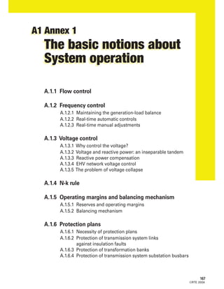
  • 38. 204 ©RTE 2004 The N-k rule defines the maximum accepted risk level. Zone1 Zoneofout-of-normevents TheN-kruledefinesthemaximumacceptedrisklevel Extentof potential powercut (MW) Unacceptable consequences limit (600MW fora“single” eventatEHV) Non-dimensioningevents (outageofanuclearsite, outageofa400kVsubstation) Lowprobability Dimensioningevents Auto-transformer outage Line outage Generationset outage Probability 400kVbusbar outage Zone3 Unacceptableriskszone: tokeepoutofthisarea,preventivemeasuresaretaken, ifnecessary,eveniftheyarecostly. Isoriskcurve (correspondingtothemaximumacceptedrisk) Zone4 Acceptableriskszone: theimplementationofpreventivemeasures mustbetheresultofatechnicalandeconomicanalysis. Zone2 Unacceptableconsequenceszone: tokeepoutofthisarea,preventivemeasuresaretaken, ifnecessary,eveniftheyarecostly.
  • 39. ©RTE 2004 205 Annex 1 -The basic notions about System operation A A.1.4 N-k rule At all times, the System operator must do what is necessary to ensure that the System remains viable following a hypothetical contingency on the nominal situation leading to the outage(1) of k facilities (cf. § 2.3). As concerns this type of contingency, he can nevertheless tolerate some risk according to a cost- reliability choice. This reference value divides the "consequences - probability" plan into four distinct domains: - the acceptable risks zone (zone 4), - the unacceptable risks zone (zone 3), - the unacceptable consequences zone (zone 2), - the risks zone for which the System operator accepts to call upon the defence plan (zone 1). If the potential consequences of a contingency are unacceptable (zone 2) or the risk run is greater than the maximum tolerated risk (zone 3), the System operator must bring the forecast power cut back to the tolerated levels or, if this is not possible, minimise it, in operational planning and in real-time operation. To do so, he may implement means inducing additional operating costs. When several solutions are possible, he must endeavour to minimise the consequences of the feared events. The N-k rule defines the maximum tolerated risk level, assessed by a reference value of the product "Event probability x Extent of power cut": the greater the probability of an event occurrence, the lower the accepted power cut (in MW). (1):This concerns the outage of facilities; the facilities shut down for maintenance or repair purposes are already declared to be out of order in the nominal state of the network.
  • 40. 206 ©RTE 2004 SNET - Provence power plant The outage of a generation unit must not have an impact on customer power supply.
  • 41. ©RTE 2004 207 Annex 1 -The basic notions about System operation A A.1.4 N-k rule The table below shows the typical events to be taken into account and, for each one of them, specifies the tolerated consequences and risks. Events to be taken Acceptable Customer Maximum extent into account power cut load shedding of power cut or load shedding Outage of a generation set NO NO 0 Outage of a 400 kV line or 400/225 kV auto-transformer NO NO 0 Outage of a 225 to 45 kV line NO (1) / YES YES 100 MW Outage of a 400 or 225 kV primary transformer NO (1) / YES YES 100 MW supplying a 225 to 45 kV grid Outage of a busbar section YES YES 600 MW at 400 and 225 kV 200 MW at 150 to 45 kV Simultaneous outage of two 400 or 225 kV generation sets NO YES 600 MW due to a common mode (load shedding) Simultaneous outage of two 400 or 225 kV generation sets YES YES 600 MW with t < 8 h (2) Simultaneous outage of two 400 or 225 kV generation sets NO NO 0 with t > 8 h (2) Outage of a double NO YES 1,500 MW 400 kV line (load shedding) (1): Unacceptable power cut when the structure is guaranteed and the network is complete (2): t = time separating the successive tripping of 2 generation sets
  • 42. ©RTE 2004 208 EDF - Saint-Laurent-des-Eaux nuclear power plant Active power reserves must be predisposed to ensure the supply-demand balance and settle congestions on the public transmission system.
  • 43. ©RTE 2004 209 Annex 1 -The basic notions about System operation A A.1.5 Operating margins and balancing mechanism A.1.5.1 RESERVES AND OPERATING MARGINS A.1.5.1.1 Reserve requirements In keeping with the role entrusted to it byArticle 15 ofAct n°2000-108, RTE ensures the balance of flows between supply and demand on the overall French power systemandsettlesanycongestionontheFrenchpublictransmissionsystem,over a period ranging from day-ahead planning (D-1) up to real-time operation (D). Each producer manages the mobilisation of the means needed to meet the demand of its customers and certain contingencies. RTE draws up its global load forecast for France and calculates the values of the reserves required to cover the different types of contingencies. The primary, secondary and tertiary controls in real time serve to manage the supply-demand balance, by using reserves set aside for this purpose. RTE evaluates the reserves that are effectively available. If they are insufficient, RTE performs adjustments on the generation facilities. A.1.5.1.2 Supply-demand balance contingencies • Load contingencies The meteorological contingency (temperature, cloudiness) has a great influence on load: thus, in autumn, winter and spring, a temperature deviation of one degree results in a load variation that may reach 1,600 MW. Likewise in summer, when the temperature is higher than 25°C, one degree more generates an extra load of up to 600 MW due to the operation of various cooling equipment (this phenomenon increases every year with the level of installation of ventilation or air conditioning systems). Another disturbance affecting load is related to the start or disconnection of loads at the beginning and end of tariff periods (off-peak hours, peak day withdrawal, etc.). • Generation contingencies Generation facilities, like all System components, are affected, as regards their operation, by a number of fortuitous events and/or limitations giving rise, in real time, to the unscheduled unavailability of a certain volume of generation.
  • 44. ©RTE 2004 210 Since 1 June 1998, the value recommended by UCTE has been determined on the basis of the curve below: This curve, with the shape: Pr = a Lmax + b2 - b is established empirically with: a = 10 and b = 150 Pr = Recommended secondary control half-range in MW Lmax = Maximum forecast load of the control area in MW for the period considered 0 0 5000 10000 15000 20000 25000 30000 35000 40000 45000 50000 55000 60000 65000 70000 75000 80000 85000 90000 900 800 700 600 500 400 300 200 100 Lmax in MW Recommended secondary reserve in MW
  • 45. ©RTE 2004 211 Annex 1 -The basic notions about System operation A A.1.5 Operating margins and balancing mechanism • International exchange variations The noteworthy increase of exchanges is accompanied by a concentration at certain times of modifications in scheduled energy interchange between control blocks, with changes that often reach several thousand MW between France and the other countries. Secondary load-frequency control is used to a considerable extent in these transitional phases. A.1.5.1.3 Definition and sizing of reserves and margins Primary reserve In an interconnected network, the primary reserve is the sum of the primary reserves of the generation sets in primary control. The primary reserve of a generation set is the power margin allocated to the primary frequency control (cf. annexA.1.2). The UCTE rule recommends a permanent primary reserve of 700 MW for France (+ 150 MW if reference frequency at 49.99 Hz / - 150 MW if reference frequency at 50.01 Hz). Secondary reserve For oneTSO or severalTSOs belonging to the same control block, the secondary reserve is the sum of the secondary reserves of the generation sets subject to secondary load-frequency control(1) . The instantaneous secondary reserve of a generation set corresponds to the upward or downward power still available under the action of secondary load- frequency control at a given time, considering the value of RSFP level N at this time.ItisequaltothecontributiontoRSFPwhentheRSFPlevelNisequalto0,the assumption used in the forecast studies. RTE determines the secondary reserve requirement for each half-hourly point: value recommended by UCTE for periods when the demand gradient (demand = load France + algebraic sum of international exchanges) is low (cf. opposite page) or increased value for periods when the demand gradient is high, with a minimum of 500 MW regardless of the demand level. Tertiary reserve Theupwardordownwardtertiaryreserveisthepowerthatcanbebroughtonline in less than half an hour. It is set up on the basis of balancing offers submitted on thebalancingmechanism(cf.§1.5.2ofthisannex)whichhaveamobilisationtime compatible with the utilisation envisaged within the scope of the normal operation of this mechanism. (1): French acronym "RSFP" for "Réglage Secondaire Fréquence Puissance".
  • 46. ©RTE 2004 It consists of two parts: • rapid tertiary reserve: power reserve that can be mobilised in less than 15 minutes, for a guaranteed period of at least one hour for each activation at least twice a day. The purpose of the rapid tertiary reserve, which has a minimum value of 1,000 MW, is to supplement the contributions to secondary frequency control. • additional tertiary reserve: power reserve which can be mobilised within a period between 15 minutes and half an hour, for a guaranteed period of at least six consecutive hours for each activation and at least once a day. The additional tertiary reserve, which has a minimum value of 500 MW, is intended to reconstitute the rapid tertiary reserve. Deferred reserve Power which can be brought on line within a time of over half an hour and the use of which is ensured for a given consecutive duration.The deferred reserve makes it possible, whenever necessary, to reconstitute the desired upward (or downward) level of tertiary reserve, therefore the operating margin level. Operating margin (or Margin) At instant t0, the operating margin for a given time t0 + d corresponds to the difference between: - on the one hand, the supply(1) known at instant t0 as normally being available at t0 + d (except for exceptional or safeguard actions), - on the other hand, the demand estimated at instant t0 as likely at t0 + d. For an upward (or downward) margin, the maximum (or minimum) generation offered will be taken into account. Reserve availabilities agreed upon between TSOs in the time range t0 + d ("common" reserves) can also be included, if necessary, in the operating margin. Links between reserves and operating margin: expressed in another way, the margin is the algebraic sum of secondary, tertiary, deferred and common reserves, which each correspond to special characteristics, and of the "balance"(2) . 212 (1): By "supply" is meant for the most part the generation available or declared as such by those in charge of scheduling for the call programmes and the generation offered as part of the normal operation of the balancing mechanism. (2):The “balance” is an indicator characterising the difference at a given time (real-time or future) between generation provided by RTE (in fact the sum of the active power set points transmitted to the producers by RTE for this time) and demand (load + exchanges) at the same time.
  • 47. ©RTE 2004 213 Annex 1 -The basic notions about System operation A A.1.5 Operating margins and balancing mechanism The current operating margin corresponds to the margin observed at current instant t0. It is established on the basis of the current values of the reserves and of the "balance" known at instant t0 and expresses the extent of the severity of the situation experienced at t0. 15-minute margin In this case, power can be brought on line in less than 15 minutes. It is made up of rapid tertiary reserve and secondary reserve and must make it possible to compensate for the outage of the largest connected generation set (which may be about 1,500 MW). What margins are to be kept? The requisite margin is the margin deemed necessary to respect a risk level predefined to make use of generation facilities so as to avoid a power system failure linked to a generation-demand balance. It is a function of the generation/demand level, the estimated reliability of the generation facilities, as well as the analysis of load contingencies, etc. Each day, on D-1, RTE defines this volume for various representative time spans and makes sure, one day ahead and then in real time, that the margin available at these time spans remain higher than the required value. It checks more particularly that the offers present on the balancing mechanism help reach this objective. Accepted risk The operating margins help cope with contingencies. Suppliers have the responsibility of setting up margins enabling them to protect themselves against the risks related to their contractual commitments. As the regulatory texts do not stipulate the minimum risk level for which the players must make appropriate provisions, the latter determine this level themselves. RTE, considering its experience in this domain, defines the risk level that it feels should be covered for the French power system as a whole.This level is defined and valid for the various time spans. Current rules are such that the likelihood of calling upon exceptional means and safeguard actions (contract interruption, customer load shedding, escalation to Pmax for generation sets, etc.), i.e. less than: - 1% at the morning peak load, - 4% at the evening peak load.
  • 48. Some figures At constant risk, the necessary margin evolves according to the time period considered: at close time spans, the required margin decreases in volume since the contingency risks decrease and the future is increasingly deterministic; conversely, at farther time spans, the volume increases because the uncertainty about the contingencies increases.The increase of volume is nonetheless not a linear function since the facilities which can be made available by the real-time period must be taken into account. The objective, such as is the practice in System operating rules, is to have in real time a margin of 2,300 MW within 2 hours and about 1,500 MW within 15 minutes. Operating margin under degraded operating conditions By definition, the constituted operating margin does not make it possible to cope with just any contingency. If it proves to be insufficient when the deadline approaches without it being possible to reconstitute it by the usual actions, one therefore has to use the means provided for operation under degraded operating conditions. In particular, when the 2-hour margin or 15-minute margin cannot be met, a "Critical alert situation for insufficient margin" message is actuated by CNES and sent to the producers (cf. see also the § "Insufficiency of balancing offers" in annex A.1.5.2). 214 ©RTE 2004
  • 49. 215 ©RTE 2004 Annex 1 -The basic notions about System operation A A.1.5 Operating margins and balancing mechanism A.1.5.2 BALANCING MECHANISM Why a balancing mechanism? As indicated previously, RTE must have margins, for daily preparation and in real time, enabling it to ensure the overall supply-demand balance for France and the solving of congestion on the French public transmission system. RTE encourages the electrical market actors to make generation facilities available to set up these margins.To this end, after extensive consultation with the various players concerned, RTE set in place a balancing mechanism on 31 March 2003 making it possible to pool the available means of generation. This mechanism features the submission of offers from the balancing participants.Any player who so desires can take part in the mechanism provided that he complies with the rules validated by the French Energy Regulation Commission. The participants submit their balancing offers. RTE calls upon these offers depending on the balancing requirements, according to the related conditions (price, conditions for utilisation of the offers and technical constraints) and while taking into account the System operating conditions.The activated offers are remunerated at the offer price. The balancing mechanism represents an annual gross physical volume (upward and downward) of about 15 TWh, thus offering a mutual interest for each participant: - for the various players, making optimum use of their withdrawal capacities or generation flexibility both in upward and downward trends, while setting all the parameters of the offer (price, period, conditions), - for RTE, constantly ensuring System reliability and getting a reference price to emerge for the settlement of imbalances. What is a balancing offer? A day ahead of time (D-1) before 4 p.m., each participant sends RTE a generation schedule, ie "call programmes"(1) for its programming entities, or a load reference and, for each of its balancing entities that he wishes to propose, submits one or more offer(s) defined by the following parameters: - balancing direction (upward/downward), - period covered by the offer, - price possibly different on previously defined flexible pricing periods, - usage conditions. (1): French acronym "PA" for "Programme d’Appel".
  • 50. For the producers, the offer volume is implicit: it corresponds respectively to Pmax - PA for the upward offer, PA - Pmin for the downward offer. For the consumers, the offer corresponds to the withdrawal or extra load volume possible compared with the forecast load. For the other players, the volume of the upward or downward offer is expressed explicitly. Submission of balancing offers The balancing mechanism operates continuously (24 hours a day) for the transmission of offers to RTE (new offers, modification or deletion of previously submitted offers) and in sequenced fashion to take into account the offers, on the basis of gate closures spread out on day D. Each gate closure is followed by a neutralisation period applying to the offers redeclarations. Over this period, an offer cannot be: - activated by RTE, - withdrawn or changed by the participant. Each player pledges not to propose the energy made available through the various offers to another player and RTE commits itself to taking into account and abiding by all the declared utilisation conditions of these offers. Mobilisation of balancing offers RTE mobilises the offers a day before or in real time, for at least one of the following causes: • P = C, to restore the overall supply-demand balance France; • Network, to remedy a congestion on the national network, on the regional network or on an international interconnection; 216 ©RTE 2004 t P Maximum power offered Pmin Call programme Upward offer Downward offer
  • 51. 217 Annex 1 -The basic notions about System operation A A.1.5 Operating margins and balancing mechanism ©RTE 2004 • System services, to reconstitute the minima required in primary and secondary reserve; • Margin, to restore the operating margin to the required level for the various future time spans. The call programme modified by RTE’s balancing requests, both on D-1 and in real time, and possibly by redeclarations of the participants, becomes the "running programme"(1) . Balancing is, quantitatively, the difference between the two powers (running programme PM and call programme PA). Running programmes in real time Call programme redeclarations Import & export schedule modifications Contingencies Balancing in imbalance situation compared with the reference of D-1 - P=C balance - Network congestion - System services - Margin Running programmes D-1 Call programmes D-1 t P Running programme Call programme Upward balancing Downward balancing Maximum power offered Pmin (1): French acronym "PM" for "Programme de Marche".
  • 52. 218 ©RTE 2004 Insufficiency of balancing offers The availability of a sufficient volume of upward and downward offers to comply with the requisite margin levels and the resolution of network congestion is checked by the CNES and URSE a day ahead of time and in real time. In case offers are insufficient, RTE warns the balancing participants according to the conditions described in the dedicated rules (all for the margins, some for network congestions): - time span greater than 8 hours: alert message on the balancing mechanism, by which RTE requests additional offers; - time span under 8 h: message "Notification of changeover (of balancing mechanism) to degraded operation", possibly preceded or followed up by the sending -via the SAS (Security and Alert System) - of the safeguard order "Critical situation due to insufficient margin" in case of non-compliance with the upward margin level required at a given time span (8 h, 2 h, 15 min). RTE can then mobilise exceptional offers, over and above any additional offers.
  • 53. 219 Annex 1 -The basic notions about System operation A A.1.6 Protection plans ©RTE 2004 A.1.6.1 NECESSITY OF PROTECTION PLANS A.1.6.1.1 Origin and nature of faults Electricity transmission facilities (lines, cables, substations) may be affected in the course of their operation by a number of insulation faults. Fault causes are usually ranked in two categories: external origin and internal origin. The first case concerns natural or accidental causes independent of the network. Two main types of external causes are distinguished: • meteorological disturbances (storm, fog, frost, wind, etc.), which are the principal cause of faults on overhead lines; • diverse and accidental causes: electric arcs between foreign bodies (branches, birds, etc.), electric arcs between various items of equipment (cranes, earthwork equipment, etc.), pollution. In the second case, the faults are due to the network itself.The internal causes are mainly equipment damage (lines, cables, transformers, instrument transformers, circuit-breakers, etc.) brought about by mechanical failures or the ageing of insulants, and untimely switching which may be due to human or equipment failure. In most cases, a fault gives rise to the appearance of a short-circuit current which must be cleared by de-energising the faulty facility. As a result, the faults which affect the various system components constitute, with regard to customers, the main cause for the interruption of the power supply. Regardless of the cause, a fault may be of two different types: it is said to be transient if, after a short insulation, the facility concerned can be re-energised (flashover of an insulator string due to an atmospheric overvoltage, for example). It is said to be permanent when it comes with damage (or presumed damage) of equipment requiring intervention for repair or inspection before putting the facility back into operation. Transmission facilities sustain about 10,000 to 12,000 short-circuits per year, the largest number of them brought about by meteorological conditions: approximately 60% due to lightning and slightly over 20% due to frost, sticky snow, rain, wind, salt pollution, etc. Equipment damage accounts for 2%, the remainder being due to various causes (contacts with vegetation and animals, incidents brought about by the users, acts of malevolence, contingencies due to unknown causes). Over and above meteorological causes, the number of short-circuits per 100 km of facilities per year is closely tied in with the voltage level: about 2-3 at 400 kV, 7-8 at 225 kV, 9-12 at 90 kV and 15-20 at 63 kV.
  • 54. ©RTE 2004 220 RTE - Inner view of a 400 kV substation relay building The protection systems are housed in substation relay buildings located near HV facilities.
  • 55. ©RTE 2004 221 Annex 1 -The basic notions about System operation A A.1.6 Protection plans A.1.6.1.2 Short-circuit currents Short-circuit currents caused by faults disturb proper System operation. They result in: - voltage drops (voltage dips) on the network, the amplitude and duration of which depend on the form -single phase or polyphase- of the faults, their location, as well as the clearance time; - heating and electrodynamic stresses in equipment which may have damaging effects if the equipment resistance limits are exceeded; - dynamic stresses (in particular, acceleration stresses) at the generation set level. As regards these different stresses, the duration of the faults is determining and the clearance time must be perfectly controlled. A.1.6.1.3 Fault clearance When a fault occurs on a network facility, the facility concerned must be de- energised by opening the one or more circuit-breakers which connect it to the rest of the network.The functions of fault detection and control of the tripping of HV equipment concerned are ensured by special devices: fault protections. The protection function is one of the most critical functions when it comes to System reliability. As shown in the above diagram, the openings are limited to the two circuit-breakers of the faulty line: the clearance is said to be "selective". Protections are expected to operate reliably (no failure or unwanted operation), selectively (tripping of only circuit-breakers necessary to clear the fault) and fast (to minimise equipment stresses and preserve the stability of generation sets). Fault SourceSource
  • 56. ©RTE 2004 All the protections of a network make up a "protection system". Protection systems come in different technical levels: 75 protection plan, 83 protection plan, 86 protection plan. Each system must be such that, in case of the failure of a protection or circuit-breaker, back-up is always ensured; this back-up may be provided locally (for example, by doubling the protections), or remotely by the protections of other network facilities. Back-up will be more or less effective (in selectivity, in rapidity, etc.) depending on the nature of the grid concerned: interconnection networks, sub-transmission networks, etc. Example of an emergency clearance: case of a remote back-up; the loss of selectivity with this type of back-up is to be noted. The protection system of meshed (or ringed) grids is more complex than the one which protects networks in a radial arrangement, because in case of a fault on a meshed network line, the current is divided into the different branches of the grid. At 400 kV, faults have to be cleared in an extremely short time so as not to jeopardise the stability of the generation sets.The protection system makes use of electronic or digital protective devices associated with interlocking between substations (accelerated underreach system, for example). The limit time for the clearance of solid three-phase short-circuits, including circuit-breakers operation time (50 ms), is about: - line faults: 70 to 110 ms, - busbar faults: 140 ms for open substations, 100 ms for gas-insulated substations, - faults with a circuit-breaker failure: 190 to 270 ms. 222 Protection operation: opening of circuit-breaker Protection failure Emergency opening by protection SourceSource Fault
  • 57. ©RTE 2004 223 Annex 1 -The basic notions about System operation A A.1.6 Protection plans At 225 kV, electromechanical protection equipment tends to give way to electronic equipment within the scope of replacement programmes, whether it be for stability requirements (substations near generation sets) or because of obsolescence. The use of interlocking between substations (protection signalling facilities, etc.), necessary in the case of "near substations", tends to develop for the other facilities (taking into account of quality of supply constraints). The maximum clearance time of solid three-phase short-circuits, including circuit-breakers operation time (70 ms), is about: - line faults: 120 to 150 ms for "near substations", 140 to 800 ms in general for the other substations (< 250 ms in the case of protection signalling facilities), - busbar faults: 95 ms for "near substations", from 600 to 800 ms for the others. At HV1, protection systems still largely make use of electro-mechanical devices; modernisation programmes lead to their replacement by equipment featuring new technology for the purpose of improving quality of supply or because of obsolescence. In sensitive areas, interlocking between substations (protection signalling facilities) may be used. The clearance time is approximately the same as the values adopted at 225 kV for "not near substations". A.1.6.2 PROTECTION OF TRANSMISSION SYSTEM LINKS AGAINST INSULATION FAULTS Considering the operating diagrams of high and extra high transmission grids, one cannot be content with using simple intensity relays, such as those used on radial networks.The network meshing imposes a more sophisticated protection system to take into account the different contributions to the fault. Schematically, the principle of this system is as follows: ICC: short-circuit current PX: protection on outgoing feeders All the protections detect and locate the fault: - the PXAs and PXCs locate the fault "outside" the facility that they protect and do not immediately command tripping; - the PXBs locate the fault on the facility that they protect and command the opening of the ends of line B. Fault Line A Line B Line C PXA Source PXA PXB PXCPXB PXC Source ICC1 ICC2
  • 58. 224 ©RTE 2004 For transmission system lines, the protection system meets the three-fold requirement of operating reliability, selectivity and rapidity. This supposes equipment redundancy, or even functional complementarity, of equipment used at each outgoing feeder level (operating reliability criterion) and, depending on the need, the implementation of a system of data exchange between the protections of the two ends of the facility (rapidity and selectivity criteria); in this last case, we speak of remote protection. Two main types of protection are distinguished: • protections using local criteria worked out on the basis of the measurement of currents and/or voltages at each outgoing feeder level: these are distance protections which serve to indicate the fault location by impedance measurement via outgoing feeder instrument transformers, which determine the location of the faults and consequently issue tripping commands and protection signalling facilities; • protections using the criterion of comparison of electrical magnitudes at the ends of the facility: the two main ones are line differential protections (current difference) and phase comparison protections (voltage/current phase deviation). A.1.6.2.1 Distance protection principle - Advantages and drawbacks The distance protection principle is outlined below: on the one hand, for faults between phases and, on the other hand, for phase-to-earth faults. Fault between phases Distance protection Phase A Phase B Phase C Current transformer Voltage transformer Impedance measurement of faulty phase-to-phase loop Impedance measurement of faulty phase-to-earth loop Earth fault Distance protection Phase A Phase B Phase C
  • 59. 225 ©RTE 2004 Annex 1 -The basic notions about System operation A A.1.6 Protection plans The fault is located at the protection level by two distance measurements: the first generally covers 80% of the length of the line, the second 120%. -The first, taking into account the errors specific to the measurement and the lack of precise knowledge about the characteristics of the facility, allows to reliably identify the fault in the facility and to proceed with immediate tripping.The fault is then said to be in "zone 1" and cleared at the "1st stage". - The second serves to cover the rest of the facility, but at a range going beyond the busbars of the opposite substation and covers, to a certain extent, the outgoing feeders connected to it. It is necessarily time-delayed so as to be selective as regards the faults which might occur and which must be cleared by local protections.The fault is then said to be in "zone 2" and cleared at the "2nd stage". The diagram below sums up this procedure, in direction A to B (the operating principles are the same in the other direction). • Advantages:This protection detects the faults beyond the facility concerned and thus offers the advantage of ensuring emergency triggering for faults occurring at substation B or farther (busbar faults, line faults improperly cleared following a circuit-breaker or protection failure). In this case, one speaks of operation under "remote back-up" conditions. • Drawbacks: On the other hand, it is relatively slow in the 2nd stage. This inconvenience can be reduced by resorting to information exchanges between the ends of the facility by means of teletransmission systems (accelerated underreach system). Furthermore, for short links, the differentiation between zones 1 and 2 reaches its limits. However, these protections can still be used by resorting to blocking systems. Outgoing feeder A Zone 1 (80 %) Zone 2 (120 %) Opening time 1st stage - Outgoing feeder A (PXA) Zone 2 (120 %) Outgoing feeder B Zone 1 (80 %) 2nd stage - Outgoing feeder A (PXA) 1st stage - Outgoing feeder B (PXB) 2nd stage - Outgoing feeder B (PXB)
  • 60. A.1.6.2.2 Principle of differential and phase comparison protections - Advantages and drawbacks The line differential protection calculates the deviation between the current values measured at both ends of the line and compares it with a predefined threshold. If this limit is exceeded, triggering occurs. The phase comparison protection works according to the same principle, but detection concerns the phase deviation between voltage and current at the two ends of the line. • Advantages: Other than their insensitivity to flow currents, these protections offer the advantage of a better selection of the fault phase(s), in particular on the conductors of two-circuit lines (case of faults simultaneously affecting the two circuits). In addition, differential protection provides efficient protection of lines with tapped connections. • Drawbacks: As a rule, these protections are insensitive to external faults and cannot ensure "remote back-up". They must therefore be combined with a distance relay. Furthermore, they require specific high-performance transmission circuits notably in terms of availability (which may themselves constitute a common mode between several facilities).The resulting cost limits its use to the 400 kV grid and to underground links. A.1.6.2.3 Utilisation limits of these protections The scope of action of distance protections, differential or phase comparison protections is limited to the clearance of low-resistance faults (fault resistance below 30 ).To clear resistive faults, specific protections the principle of which is to measure the homopolar power are used.These protections have the drawback of being slow, which is acceptable because this type of fault is less constraining. 226 ©RTE 2004 Transmission of values of I1 and I2 I1 Tripping if |I1- I2 | > Iseuil I2 Tripping if |I1- I2 | > Iseuil Iseuil = tripping tuning threshold Differential Differential Transmission of values of 1 and 2 I1 I2 Tripping if | 1 - 2 | > seuil V1 V2 Tripping if | 1 - 2| > seuil : Phase angle between V and I seuil = tripping tuning threshold Phase comp. Phase comp.
  • 61. (1): In these situations, the interlocking system is secured. (2):The interlocking system is implemented depending on customer constraints. (3):This time corresponds to the clearance of faults in zone 1 and zone 2 with accelerated underreach system. (4):This is a simplified protection for the clearance of polyphase faults. (5): French acronyms: "CPEC" for "Changeur de Prise En Charge", "TPN" for "Transformateur de Point Neutre". 227 ©RTE 2004 Annex 1 -The basic notions about System operation A A.1.6 Protection plans A.1.6.2.4 Types of equipment and performances for the different voltage levels The table below lists the equipment used and average performances for common cases (including the operating time of circuit-breakers). It shows the redundancy mode chosen to ensure operating reliability. The protection against resistive faults is not mentioned, but is systematically provided. A.1.6.3 PROTECTION OF TRANSFORMATION BANKS Schematically, an EHV/HV transformation bank consists of: • the transformer itself and associated equipment: - the on-load tap changer CPEC(5) , - the neutral point transformer TPN(5) , making it possible to recreate an HV neutral in case of aY-delta connection, Protection Protection Interlocking Standard Network n° 1 n° 2 system performances Comments (in ms) 400 kV distance distance YES (1) 70 400 kV differential distance YES (1) 70 Strategic double lines, tapped connections 225 kV distance distance YES (2) 80 (3) 225 kV phase distance YES (1) 80 Stability constraints HV1 distance distance YES (2) 80 (3) EHV/HV substations HV1 distance back-up (4) YES (2) 80 (3) 225 kV distance nil YES (2) 210 (3) Former layouts of electromechanical HV1 distance nil 210 drawings
  • 62. - the earthing reactor RPN(1) of the EHV neutral point or HV neutral point, - the auxiliary services transformer TSA(1) , powering the substation auxiliaries. It is connected either to the transformer tertiary or to the TPN (Y-delta transformer) secondary, • the primary link, situated between the circuit-breaker on the primary side (EHV) and the transformer, • the secondary link, included between the transformer secondary and the instrument transformers installed on the HV side. The protection of the transformation bank is part of specific measures coordinated with the protection of lines and substation busbars. It is broken down according to the following three sub-units. A.1.6.3.1 Protection of the transformer and associated equipment Transformer protection is ensured according to the following principles: - Buchholz protection, which is meant to clear faults in the transformer by detecting oil movements or the presence of gas, subsequent to an internal disruptive discharge, - tank earth protection, which supplements the foregoing protection and detects an internal or external disruptive discharge between a live element and the transformer tank by measuring the current flowing in the tank earth connection (which requires the tank to be insulated from the ground by insulating blocks). The associated equipment (CPEC,TPN,TSA) is protected by separate equipment of the same type as that protecting the transformer: Buchholz protection, tank earth protection or neutral current relay as the case may be. EHV busbars HV busbarsBushing Oil circuit Oil conservator EHV busbars zone Primary link Transformer Bushing: Core-type current transformer Secondary link HV busbars zone Bushing Tank earth Circuit-breakerInsulating blocks Buchholz Selector switch disconnector Selector switch disconnector Circuit-breaker Instrument combined transformer Transformation bank diagram 228 ©RTE 2004 (1): French acronyms: "RPN" for "Réactance de Point Neutre", "TSA" for "Transformateur de Services Auxiliaires".
  • 63. 229 ©RTE 2004 Annex 1 -The basic notions about System operation A A.1.6 Protection plans A.1.6.3.2 Primary link protection The primary link is generally very short; it therefore includes no particular protection.The faults affecting this link are cleared as busbar faults. A.1.6.3.3 Secondary link protection Regardless of the plan, the protections associated with the secondary link carry out several functions: - main secondary link protection, - back-up secondary link protection, - back-up protection on EHV side (clearance of transformer contribution to an EHV fault), such as, for example, the tripping of the transformer to back up the main protection of EHV busbars or for a poorly-cleared EHV fault, - back-up protection on HV side (for the purpose of clearing transformer contribution to an HV fault), - HV ring opening protection (action on HV connection circuit-breaker). A.1.6.3.4 Transformer protection performances The table below shows, for the various plans, the performances of the different busbar protections used on the transformers (operating time in milliseconds, including circuit-breaker opening): Electro- 225 kV 400 kV - 75 400 kV - 75 400 kV - 86mechanical and HV 83 evolution 83 Circuit-breaker operation 80 70 55 55 55 Buchholz 160 110 95 95 95 Tank earth connection 160 110 95 95 95 Secondary link fault 180 90 85 85 75 EHV back-up 1,300 1,700 580 580 1,700 HV back-up: normal 2,500 to 3,500 3,200 2,200 2,200 2,200 CB(1) open 500 - 400 400 - Ring opening HV:bus coupler CB 1,300 400 to 600 - - - HV transformer CB 2,500 to 3,500 2,000 to 2,500 - - - (1): CB = circuit-breaker.
  • 64. A.1.6.3.5 Service resumption In order to facilitate analysis prior to resuming service after the tripping of a transformer, the information relative to the causes of the outage has been ranked in three levels: • Certain fault: the fault is on the transformation unit and any attempt to restore voltage is prohibited. It concerns a tripping by Buchholz (transformer, TSA or TPN), secondary link differential (or cable earth), CPEC fault, maximumTSA neutral intensity, maximum tertiary current intensity. • Uncertain fault: the fault is inside or outside the transformation bank and one may try, after analysis, to re-energise. It concerns a tripping due to a tank earth fault (example: disruptive discharge of a terminal spark gap) or by EHV back-up protection. • External fault: the fault occurs outside the transformation bank and it is normal to try to re-energise the transformer. It is a fault triggered by an EHV or HV busbar fault or circuit-breaker failure, HV back-up protection, maximumTPN or RPN neutral intensity. A.1.6.4 PROTECTION OF TRANSMISSION SYSTEM SUBSTATION BUSBARS "Busbar faults" are faults located in the substation within the area delimited by the current measurement transformers installed on outgoing feeders.This area is called "busbar zone". Apart from their effect on equipment, these faults can be particularly constraining for network stability at EHV, and for customer quality of supply on the EHV and HV sub-transmission networks. As a result, particular protection systems are implemented to detect and locate the faulty busbar section and de- energise it. Their performances are adapted according to the roles of each network: interconnection, sub-transmission, etc. Generally speaking, the system used to clear busbar faults on EHV networks is made up of: • a differential busbar protection, performing fault clearance by local opening, at the substation concerned, of the bus coupler circuit-breakers and switched busbar circuit-breakers delimiting the faulty busbar section and of the circuit- breakers of outgoing feeders switched onto this busbar section; • a busbar ring opening protection, providing back-up and separating the faulty busbar section from the rest of the substation (ring opening of busbars), completed by the natural second-stage operation of the distance protections of the outgoing feeders adjoining the faulty busbar section, thus ensuring total fault clearance. The operating principle of these systems is presented hereafter. ©RTE 2004 230
  • 65. 231 ©RTE 2004 Annex 1 -The basic notions about System operation A A.1.6 Protection plans A.1.6.4.1 Busbar differential protection The busbar differential protection performs the sum of the currents on the various substation busbar sections. If it is not nil on a section, the protection detects a busbar fault. The fault is then cleared by the local opening of the circuit-breakers of the outgoing feeders powering the faulty busbar section, as well as connecting or section circuit-breakers adjoining it. This function is carried out by a single, centralised equipment item, independent of outgoing feeder protections. Busbar differential protection general diagram In case of a busbar fault, the differential protection makes only the circuit- breakers connected to the faulty busbar section trip. The busbar differential protection must therefore know the substation electric diagram. To do so, it uses the positions of the selector switch disconnectors of the various outgoing feeders. A.1.6.4.2 Busbar ring opening protection Fault clearance is carried out in two stages: 1) opening, in the faulty substation, of the bus coupler circuit-breaker to separate the busbar sections and thereby isolate the faulty busbar from the rest of the substation; 2) opening, in the remote substations, of the outgoing feeders still supplying the fault. Fault I4 I2 I3 Ifault I1 Busbar differential protection 1 2 Tripping 1 No trippingBusbars 1 : I1 + I2 + I3 = 0 2 TrippingBusbars 2 : I1 + I4 = Ifault ≠ 0 Current transformer → Ii
  • 66. 232 ©RTE 2004 RTE - New transmission substation digital instrumentation and control series (French acronym ELECTRE)
  • 67. 233 ©RTE 2004 A.1.6.4.3 Supervision protection Supervision protection is a particular busbar ring opening protection, making use, to ensure the ring opening function, of a simplified differential protection taking into account only the sum of the currents going through the outgoing feeders independently of their switching operations. This protection, used solely at 400 kV to protect strategic substation back-ups, offers the advantage of being more rapid than a conventional ring opening protection. A.1.6.4.4 Implementation and performances The table below lists the performances of the busbar protections used at the different voltage levels (including circuit-breaker opening time: 50 ms at 400 kV and 50 to 80 ms at 225 kV).The main protections are noted "Pp" and the back-up protections "Ps". Annex 1 -The basic notions about System operation A A.1.6 Protection plans Network Technical level Busbar protection Clearance time 400 kV 75 protection plan Pp: busbar differential 70 ms 83 evolution Ps: busbar ring opening Bus couplers: 250 to 380 ms(1) and 86 protection plan Remote CB (3) : 380 to 590 ms(1) Strategic 75 protection plan Pp: busbar differential 70 ms 400 kV substations 83 evolution Ps: supervision Bus couplers: 105 ms and 86 protection plan Remote CB: 370 to 500 ms Interconnection 83 protection plan Pp: busbar differential 70 ms 225 kV 225 kV and HV Ps: busbar ring opening Bus couplers: 320 ms Remote CB: 490 ms Sub-transmission Electromechanical Pp: busbar ring opening(2) Bus couplers: 380 to 560 ms(1) 225 kV and HV 225 kV and HV Remote CB: 600 to 800 ms(1) protection plan (1): Depending on the technical levels. (2): Some 225 kV substations are equipped with more effective busbar protections, depending on their strategic importance with regard to customers.The installation of more effective protections in HV substations is considered on a case-by-case basis after an economic calculation according to the quality of supply needs. (3): CB = circuit-breaker. Worthy of note is the particular case of gas-insulated substations which, as a rule, are equipped with a busbar differential protection regardless of their voltage level.
  • 68. ©RTE 2004 234 RTE - Airborne works on an EHV line