VIP Call Girls Service Kondapur Hyderabad Call +91-8250192130
Unit 2
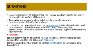
1. SURVEYING
• Surveying is the art of determining the relative positions points on, above
or beneath the surface of the earth.
• Surveying, a means of making relatively large-scale, accurate
measurements of the Earth’s surfaces.
• It includes the determination of the measurement data, the reduction and
interpretation of the data to usable form, and, conversely, the
establishment of relative position and size according to given measurement
requirements.
• functions:
(1) the determination of existing relative horizontal and vertical position,
such as that used for the process of mapping,
(2) the establishment of marks to control construction or to indicate land
boundaries
2. OBJECTIVES OF SURVEYING
• To take measurements to determine the relative position of existing
features or near the ground.
• To layout or to mark theposition of the proposed structures to the
ground.
• To determine areas, volumes and other related quantities.
3. Types of surveying
• Plane surveying
curvature of the earth is not considered.
upto 260 sq.km
• Geodetic surveying
curvature of the earth is considered.
4. Classification of survey
Based upon the nature of field survey
1. Land surveying
2. Marine/navigation surveying
3. Astronomical surveying
Based on the object
of survey
1.Engineering survey
2.Military survey
3.Mine survey
4. Geological survey
5.Archaeological
survey
Based on instruments
used
1.Chain surveying
2.Theodolite surveying
3.Transverse surveying
4.Triangulation
surveying
5.Tachaeometric
surveying
6. Plane table
surveying
7.Photographic
surveying
8.Aerial surveying
9. Compass surveying
5. Principles of surveying
1. Location of a point by measurement from two points of reference
relative points to be surveyed located by measurement from atleast two points
of reference
2. Working from whole to part
Used in extensive areas
Survey started by establishing a system ofcontrol points with high precision.
Minor ponts with low precision.
Control points are established by triangulation or by running a transverse
surrounding the area.
6. Measurement of distances
1. Direct method
Distances are measured using tapes, chains etc.
2. Computative method
Calculation using triangulation, tachaeometry
7. Computation of area
• By dividing the area into triangles
• Into squares
• Into rectangles
1. Middle ordinate rule
2. Average ordinate rule
3. Trapezoidal rule
4. Simpson’s rule
8. Trapezoidal rule
• Base line is divides into equal parts and ordinates drawn.
• The area by trapezoidal rule is the product of half of the distance between the adjacent ordinates
and the total sum of the first and the last ordinates and twice the sum of intermediate ordinates.
9. Simpson’s rule
• Odd number of ordinates
• Boundaries between the end of the ordinates are
assumed as parabola.
10. Chain
• Straight links of galvanized mild steel wire bent into rings at the ends
and joined each other by the small circular rings.
• Rings offer flexibility.
• Ends has brasss handles with swivel joint.
• Length the centres of consecutive rings.
• Length of chain + outside of one handle to the outside of the other
handle.
11. Types of chain
i. Metric chain
ii. Gunter’s chain/surveyor chain
iii. Engineer’s chain
iv. Revenue chain
v. Steel band/ band chain
12. Metric chain
• Available length: 5, 10, 20 and 30 m.
• IS: 1492-1970 covers the requirement.
• Tallies @ every 1m for 5 m and 10 m chainand every 5m @ 20 and
30m chain.
13. Gunter’s chain/ Surveyor chain
• 66 feet long and consist of 100 links and each link being 0.6ft and
7.92 inches long.
• 66ft is adopted
• When measurements are required in furlongs are miles, 10
gunterschain are used.
14. Engineer’s chain
• 100 ft long and consist of 100 links and each link being 1 feet long.
• At every 10 links, brass tags are fastened.
• The distances measured are recorded in feet and decimals.
15. Revenue chain
• 33 ft long andconsist of 16 links. Each link being 2 1/16 feet long.
• Used mainly in measuring fields in cadastral survey.
16. Steel band/band chain
• It consist of a long narrow strip of blue steel, of uniform width of12
to16 mm and thickness of 0.3 to 0.6 mm.
• Metric steel bands are available in lengths of 20 or 30m.
• It is divided by brass studs at every 20cm and numbered at every
meter.
• Careful chainman.
• Steel bandis lighter than the chain and is easier to handle.
17. Instruments used in chain surveying
Chain Arrows Pegs Ranging rods
Cross staff Offset rods
18. Compass surveying
• When no.of base slines exceed, chain surveying alone can not be
done.
• Angles b/w the adjacent sides has tobe included.
• Compass – instrument tomeasure angle.
1. Prismatic compasss
2. Surveyor’s compass
19. Prismatic compass
• Most suitable for rough survey where speed is more important.
• Commonly used in preliminary survey for roads, railways, military purposes,
rough traverse etc.
• It is not suitablein places with magnetic rock, iron ore iron basedindustrial areas.
• It is less accurate than theodolite.
20. Surveyor’s compass
• This is not often used for land surveying
• It is similar to prismatic compass except that it has another plain sight having an
arrow vertical slit in place of prism.
• The graduated dial isin quadrants and fixed to the box.
• Te readings are taken through naked eyes only.
21. LEVELLING
• Art of determining the relative heights of points on theearth surface.
• Deals with measurements in vertical planes.
• Instruments used for levelling : Dumpy level, levelling staff
22. Level
• Instrument which is used for levelling is known as a level.
• Purpose: To provide horizontal line of sight.
Accessories
1. Telescope to provide line of sight
2. A level tube to make the line of sight horizontal
3. A levellig head to bring the bubble in its centre of run.
4. The tripod to support the above parts of the level.
23. Technical terms used in levelling
1. Level surface – any surface parallel to the thesurface of the earth
2. Horizontal plane- any plane tangential to the level surface
3. Datum- imaginary surface or line to which elevations are referred to.
4. Reduced level/elevation- vertical distance of a point above or below the datum
5. Line of collimation /line of sight – imaginary line passing through the cross hair at the
diaphragm and the optical centre of the class and its continuation.
6. Bench mark – fixed point or mark of known elevation with reference to datum line.
7. Back sight- first staff reading taken on a point of known elevation in any set up of the levelling
instrument.
8. Fore sight- last staff reading. It indicates shifting
9. Intermediate sight – any other reading taken b/w B.S & F.S
10. Change point/ turning point – a point on which both B.S& F.S readings are taken
11. Height of instrument –the reduced level of the line of collimation
24.
25. Classification of levelling
1.Simple leveling
To find the differencein level b/w any two points.
Instrument placed b/w 2 points and the B.S & F.S readings t aken.
2.Differential levelling
Simple levelling adopted in successive stages.Adopted when
i. The points are at greater distance apart
ii. The difference in elevation b/w the points is more
iii. There are obstruction b/w the points
3. Fly levelling
Differential levelling performed to establish a temporary bench mark from
a known bench mark.
26. Methods Of Reducing Levels : 1. Height Of Collimation Or Height Of Instrument Method
• H.I iscomputed by adding a B.S reading to the R.L of the BM on which the bench mark
reading was taken.
• Staff readings taken from this setting are deducted from the height of the instrument to
get the reduced level of the points.
27. Methods of reducing levels :2. Rise and fall method
• In this method, the difference in level b/w 2 points are modified.
• If the point is above,the forward staffreading will be smaller than the
immediately preceeding staff reading and the difference b/w the staff
reading is called as rise and the vice versa called as fall.
28.
29. Contours
• A contour is an imaginary line of constant elevationon the ground
surface.this is the trace formed by the intersection of a level surface
with the ground surface
• Contour line: if the several ground points of equal elevation are
plotted on drawing ,a line joining thsese points is called contour line.
• Contour interval: on a given map, the successive contour lines
represent elevations differing by a fixed vertical distance.
• Horizontal equivalent: hori.distance b/w 2 consecutive contours.
30. Properties of contour
• Hori. Distance is inversely proportional to slope.
• On uniform slopes, contour lines are spaced equally
• Along plane surface, contour lines are straight and parallel.
• As contour lines are repreentation of level lines, they are perpendicular to teh
line of steepest slope.
• Contour lines indicate either a summit or depression
• Do not merge or cross one another except in the rare cases of vertical surface or
overhanging ground surface as a cliff or cave
• A single contour line cannot exist b/w 2 contour lines of higher or lower
elevation.
31. BRICKS
• Regular standard sizes from a properly processed natural soil.
• It is made from the soil containing the alumina (20- 30%),silica (50-
60%), iron oxide (5-6%) and less % of lime and magnesia.
• Size : 190mm x 90mm x 90mm.
32. Manufacturing of bricks
4 stgaes
Preparation of soil Moulding Drying Burning
Preparation of soil
• Removal of loose
materials at top.
• Soil is dried and spread
• Left for few weeks to
mellow
• During pugging,
ingredientsare added
and turned up and
down by men or pug
mill
Moulding
• The plugged clay is
moulded tothe required
shape in moulds.
• Done on a levelled
ground or on a table
manually or by
machines
Drying
• Moulded bricks are
alloed to dry for 7 to
14days in a specially
prepared drying bed
under shelter.
Burning
• Done to attain
adequate strength,
hardness, less
moisture absorbent
and durablity.
• Burning is done in
clamps or kilns.
33. Intermittent kiln
• Operations are in the order of loading of bricks,firing, cooling, unloading.
• Overground kiln of rectangular shape with thick outside walls.
• Trenches with small openings present for the passage of flue gas.
• Dampers are also present
• Above thetrnch bricks are laid with gaps to hot flue gas to reach.
• Flue gas circulation for3 to 4 days nd alloed to cool for a week.
34. Hoffman’s kiln
• Chamber 1 is loaded with raw bricks chambe 2 is empted of cooled down burnt
bricks. Bricks in chamber 3,4,5and 6 are coolingbricks are stacked in 7,8 which are
supplied with fuels.raw bricks in 9,10,11 and 12 are heated by hot flue gas before
they escape through the chimney.
35. Quality classification of bricks
First Class Brick
• Table moulded and they are burnt in the
kilns.
• Well burnt and regular in shape
• Edges are sharpand well defined.
• Hard and sound
• Surface is smooth clearand free from
cracks.
• Water absorption should not be less that
onesixth of the weight of the water when
kept immersed for sixteen hours.
• When 2 bricks struck against each other,
metallic ringing sound is produced.
• When soaked in water for 24 hours and
dried inshade does not provide
efflorescence.
• It should not break when dropped from a
height of 1 to 2m
• Specific gravity = 1.8
• No mark can be produced on it with finger
nails.
• Minimum crushing strength = 10.5
N/sq.mm
Second class brick
• These bricks are ground moulded
and burnt in kilns.
• well burnt and The edges may not
be sharp and uniform.
• The surface may be some what
rough.
• Free from lumps and cracks
• When 2 bricks struck against each
other, metallic ringing sound is
produced.
• Minimum crushing strength =
7N/sq.mm
Third class brick
• Light yellowish colour
• Not well burnt
• Soft
• When 2 bricks struck against
each other, dull sound is emitted
• It is associated with flaws and
cracks.
• Edges are irregular and surface
is rough
36. Qualities of good brick
• Perfect edges, adequately burnt, uniform red or copper colour and free
from cracks.
• No impression is left when scratched with finger nails.
• Clear ringing sound when struck with each other
• Should not break when fall from a height of 1m
• Should be homogeneous and compact throughout the brick without any
voids or grit
• % of water absorption less than 20
• No deposits of salts when soaked and dried
• Less thermal conductivity and sound proof.
• Minimum crushing strength of 3.5N/mm2.
37. Test on bricks
• Water absorption test
• Compressive strength test
• Efflorescence test
• Structure test
• Shape and size test
• Soundness test
• Hardness test
38. STONE& CLASSIFICATION
• These are the materials obtained from rock
BASED ON GEOLOGICAL FEATURE
1. Igneous rock
Formed by cooling of magma
Eg. Granite, basalt
2.Sedimentary rock
Formed by deposition of products
which are carried out by rain, wind
etc
Eg. Sandstone, gypsum, limestone
3.Metamorphic rock
When the other two rocks are
subjected to great heat and pressure,
it changes the character and is
formed.
Eg. Slate, marble
BASED ON PHYSICAL FEATURE
1.Stratified rock
Possess planes of stratification,
such rocks can easily splits up.
2. Unstratified rock
May be of crystalline granular or
compact granular
3.Foliated rock
Have the tendency to split up in a
definite direction only.
BASED ON CHEMICAL CHARACTER
1.Silicious rock
Rocks are hard and durable
Eg. Granite
2.Argillaceous rock
Durable and hard but brittle
Eg. Slates
3.Calcareous rock
Durabilty depends on constituent
present in the surrounding
atmosphere
Eg. marble
39. Qualities of good stone
• Shouldhave high crushing strength
• Should have unifor colour , compact, fine crystalline structure
• Should not absorb water more than 0.6% by weight
• Should be highly resistant against the effects of atmosphere and fire
• Should be highly durable
• Should be easily carved and dressed
• Stones forworks lie construction of walls, piers, dams etc should be tough and hard.
• Stones for roadwork and railways as ballast should be strongwith crushing strength.
• Stones forbuilding work should be easily moulded, cut and carved.
• Should have acid resistant qualities, the percentage of wear should be greater than 3 andshould
be free from any soluble matter
40. Uses of stone
• For foundations, walls, columns, arches,lintels, roofs, floors etc
• For facing work of masonry
• For concreteand road as coarse aggregate
• For railways as ballast
• For bridges as floors, piers, abutments, retaing walls etc
• For light houses and dams
41. Test on stones
• Acid test
• Attrition test
• Absorption test
• Brad’s test
• Crushing strength test
• Hardness test
• Impact test
• Smith’s test
42. SAND
• Sand basically consists of quartz.
• Size : 4.75mm to 0.075mm
• Sand is obtained from pits, river beds, stream beds and crushed
stones.
• Sea sand not suitable
• Sometimes stones are crushed and used.
• Main impurities : clay, silt, sand, salt, mica and organic matter.
• For civil engineering works, maximum of 8% silt and 2 to 3%of mica
are allowed.
43. Classification of sand
BASED ON NATURAL SOURCES
1.Pit sand
excaved from a depth of 1 to 2 m
from the ground level
Consist of sharp angular grains, free
from salts.
2.River sand
Obtained from banks of river
It consists of fine rounded grains
Available in clean condition.
3. Sea sand
Obtained from sea shores
Consist of fine rounded grains and
salt
It attracts moisture from
atmosphere
BASED ON SIZE OF GRAINS
1.Fine sand
Passing sieve size 1.5mm
Used for plastering
2.Coarse sand
Sand passing through screen with
opening of 3.17mm
Used for masonry work
3.Gravel sand
Sandpassing thorugh a screen
with opening of 7.62mm
Used for concrete work.
44. Qualities of good sand
• Should be completely inert.
• Grains should be sharp, strong & angular.
• Should not contain any hygroscopic salts (i.e., CaCl2, MgCl2, etc.).
• Should not contain clay & silt; usually 3-4% clay & silt is ordinarily
permitted for practical reasons.
• There should be no organic matter.
45. Bulking of sand
• Bulking of fine aggregate or sand is the phenomenon of increase in sand volume due to the
increase of moisture content.
• the moisture content in the sand makes thin films around sand particles. Hence, each particle
exerts pressure. Thus they move away from each other causing increasing in volume.
• The bulking of the aggregates is dependent on two factors:The fineness of the aggregates,
Percentage moisture content
• A fully saturated fine aggregate does not show any bulking.
• The rate of bulking is inversely proportional to the size of the aggregates.
46.
47. STEEL
• Steel is a ductile alloy consisting of iron and carbon
• Based on carbon carbon content it is of 3 types
1. Low carbon or mild steel : carbon content upto 0.25%
2. Medium carbon or medium hard steel : carbon content from 0.25% to 0.70%
3. High carbon or hard steel : 0.70 to 1.5%
48. Properties and uses
MILD STEEL
• Fibrous structure
• Ductile and malleable
• High compressive and high tensile
strength
• Can be magnetised, welded,
forged and revetted
• Can be hardened and tempered
• Sp.Gr = 7.8
• Melting point = 1400◦ C
• Used to manufacture tools,
machine parts, tubes, sheet metal,
tin plate and structural steel
MEDIUM HARD STEEL
• High strength than mild steel
• Hardened to certain extent
• Tougher and harder than mildsteel
• Can not be easily forged or
welded
• High resistance for shocks and
vibrations
• Used to manufacture machine/
engine components, boiler plates,
rails, hammers, pressing dies,
structural steel, agricultural
implements, aero engine cylinder,
springs etc.
HARD STEEL
• Granular structure
• Very hard and tougherthan other steel
• Possible to magnetise permanently
• Veryhard compressive and tensile strength
• Can be tempered and hardened
• Very high resistance for shocks and
vibrations
• Difficult to forge
• Used in the manufacture of plates,
cutlery,springs, iminer’s drills, heavy tools,
sledge hammers, axes, planning and slotting
machines, lathes etc
49. Manufacture of steel -5 different processes
1. Bessemer Process
• Bessemer convertor is
used which rotates
about the hori. Axis.
• Pig iron is filled and hot
blast iron is forced.
Impurities are oxidized
and reddish yellow flame
is seen.
• Air is stopped and
ingredients added.
• Blast is again started and
moten metal is poured.
2. Cementation process
• Dome shaped furnace called
the cementation furnace is
used.
• Pig iron is first converted to
wrought iron.
• After adjusting the carbon
content,steel is obtained
3. Open hearth process
• Mixture of preheated air and
coalgas as fuel.
• The steel produced is
homogenous and highly
reliable
4. Electric process
• Raw material is melted using
electricity
• Similar to bessemer
• Control of temperature is
feasible
• Quick process
• Special grades of steel are
produced
5. Duplex process
• Combination of Bessemer and open
hearth process
50. Steel sections
1.BARS
• Round/square
• Square section: 5 to 32mm
• Round dia : 6 to 32mm
• Both of length 10 to 12m
• Square bars are used for
railing or for grill work
• Round bars used in
reinforced concrete and
brick work
2. PLATES
• Rolled plates with
thickness 5 to 28mm and
with maximum area of
30sq.m are available
• Thin plaes with 5 mm
thicknes are called sheets
• Used in flanges of beams
and columns and as
column bases.
3.FLATS
• Plates with longer
length and shorter
width
• Width :18 to 500mm
• Thickness: 3 to 80mm
• Costlier and used in grill
works and railings
4.ANGLE SECTION
• Equal and unequal
length and different
sizes
• Used in steel rod
trusses,steel
columns, beams and
as stiffness girders
5.CHANNEL SECTION
• 2 flanges and web
• It is designated by the
dimensions and are available
in different sizes.
• used in steel framed
structures, girders and steel
bridges
6.I and T sections
• Named based on the shape
• I section is referredas rolled steel joist and used
for floor, beams, lintels, columns etc
• T sections are used for steel roof trusses, in
built sections, water tanks, bridges.
• Made economical by concentrating the material
on the flanges where the bending stresses are
maximum
7.Expanded metal
• Plain or ribbed steel sheets are cut and
expanded to form expanded metal.
• Used in ferro cement concrete works
• Welded fabric with ribbed mesh has a
rectangular or square mesh isanother form
of mesh used in the construction