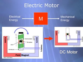
4. DC Motor Principle
Whenever a current-carrying conductor is placed in a
magnetic field, it experiences a mechanical force which
collectively produce a driving torque that sets the
armature rotating whose direction is given by Fleming’s
Left-hand Rule.
6. Back EMF/Governor
The term back electromotive force, or just back-EMF,
is most commonly used to refer to the voltage that
occurs in electric motors where there is relative motion
between the armature of the motor and the magnetic
field from the motor's field magnets, or windings.
15. D.C. Motor Characteristics
1. Torque and armature current i.e. Ta/Ia characteristic.
It is known as electrical characteristic.
2. Speed and armature current i.e. N/Ia characteristic.
3. Speed and torque i.e. N/Ta characteristic. It is also
known as mechanical characteristic.
16. Characteristics of Series Motors
1. Torque and armature current i.e. Ta/Ia characteristic.
It is known as electrical characteristic.
At light loads, Ia and hence Φ is small. But as
Ia increases, Ta increases as the square of the
current. Hence, Ta/Ia curve is a parabola .
After saturation/heavy Loads, Φ is almost
independent of Ia hence Ta ∝ Ia only. So the
characteristic becomes a straight line.
The shaft torque Tsh is less than armature
torque due to stray losses.
As practically Φ is equals to Ia
17. Characteristics of Series Motors
2. Speed and armature current i.e. N/Ia characteristic.
With increased Ia, Φ also increases. Hence, speed varies inversely as armature current.
When load is heavy, Ia is large. Hence, speed is low (this decreases Eb and allows more
armature current to flow). But when load current and hence Ia falls to a small value,
speed becomes dangerously high.
Hence, a series motor should never be
started without some mechanical (not
belt-driven) load on it otherwise it
may develop excessive speed and get
damaged due to heavy centrifugal
forces so produced.
It should be noted that series motor is
a variable speed motor.
As practically Φ is equals to Ia
18. Characteristics of Series Motors
3. Speed and torque i.e. N/Ta characteristic. It is also
known as mechanical characteristic.
When speed is high, torque is
low and vice-versa.
19. Characteristics of Shunt Motors
1. Torque and armature current i.e. Ta/Ia characteristic.
It is known as electrical characteristic.
Assuming Φ to be practically constant
(though at heavy loads, φ decreases
somewhat due to increased armature
reaction)
Hence, the electrical characteristic is
practically a straight line through the origin.
Shaft torque is shown dotted. Since a heavy
starting load will need a heavy starting
current, shunt motor should never be started
on (heavy) load.
As Φ is practically constant
20. Characteristics of Shunt Motors
2. Speed and armature current i.e. N/Ia characteristic.
As Φ is practically constant
As Eb is also practically constant, speed is, for most purposes, constant
But strictly speaking, both Eb and Φ decrease
with increasing load. However, Eb decreases
slightly more than φ so that on the whole,
there is some decrease in speed.
The drop varies from 5 to 15% of full-load
speed, being dependent on saturation,
armature reaction and brush position.
Hence, the actual speed curve is slightly
drooping as shown by the dotted line.
But, for all practical purposes, shunt motor
is taken as a constant-speed motor.
21. Characteristics of Shunt Motors
3. Speed and torque i.e. N/Ta characteristic. It is also
known as mechanical characteristic.
When speed is high, torque is
almost constant.
As Φ is practically constant
22. Compound Motors
These motors have both series and shunt windings.
If series excitation helps the shunt excitation i.e. series flux is in the same direction
(a) then the motor is said to be cumulatively compounded.
If on the other hand, series field opposes the shunt field (b), then the motor is
said to be differentially compounded.
25. Power Stages
A − B = copper losses and B − C = iron and friction losses
26. Factors Controlling Motor Speed
the speed can be controlled by varying
(i) flux/pole, Φ (Flux Control)
(ii) resistance Ra of armature circuit (Rheostatic Control)
(iii) applied voltage V (Voltage Control)
27. Speed Control of DC motors
(i) Variation of Flux or Flux Control Method
It is seen from above that N ∝ 1/Φ. By
decreasing the flux, the speed can be
increased and vice versa. Hence, the name
flux or field control method. The flux of a
d.c. motor can be changed by changing Ish
with help of a shunt field rheostat.
Since Ish is relatively small, shunt field
rheostat has to carry only a small current,
which means I2R loss is small, so that
rheostat is small in size. This method is,
therefore, very efficient.
28. Speed Control of DC motors
(ii) Armature or Rheostatic Control Method
This method is used when speeds below the no-load speed are required. As the supply
voltage is normally constant, the voltage across the armature is varied by inserting a
variable rheostat or resistance (called controller resistance) in series with the armature
circuit as shown in Fig. (a).
As controller resistance is increased, potential difference(p.d.) across the armature is
decreased, thereby decreasing the armature speed. For a load constant torque, speed is
approximately proportional to the p.d. across the armature. From the speed/armature
current characteristic [Fig. (b)], it is seen that greater the resistance in the armature
circuit, greater is the fall in the speed.
29. Speed Control of DC motors
(iii) Voltage Control Method
a) Multiple Voltage Control
b) Ward-Leonard System
30. Starter For DC Motor
When the motor is at rest, there is, as yet,
obviously no back e.m.f. developed in the
armature. If, now, full supply voltage is
applied across the stationary armature,
it will draw a very large current because
armature resistance is relatively small.
This excessive current will blow out the fuses and, prior to that, it will damage the
commutator and brushes etc. To avoid this happening, a resistance is introduced in
series with the armature (for the duration of starting period only, say 5 to 10
seconds) which limits the starting current to a safe value. The starting resistance is
gradually cut out as the motor gains speed and develops the back e.m.f. which
then regulates its speed.