SlideShare a Scribd company logo
1 of 24
Download to read offline
Expriment No. Date of Perform Date of Submission Expriment No. Date of Perform Date of Submission
Experiment-1 29-Aug-2022 29-Aug-2022 Experiment-1 02-Sep-2022 02-Sep-2022
Experiment-2 12-Sep-2022 12-Sep-2022 Experiment-2 09-Sep-2022 09-Sep-2022
Experiment-3 19-Sep-2022 19-Sep-2022 Experiment-3 16-Sep-2022 16-Sep-2022
Experiment-4 10-Oct-2022 10-Oct-2022 Experiment-4 30-Sep-2022 30-Sep-2022
Experiment-5 17-Oct-2022 17-Oct-2022 Experiment-5 07-Oct-2022 07-Oct-2022
Experiment-6 31-Oct-2022 31-Oct-2022 Experiment-6 14-Oct-2022 14-Oct-2022
Experiment-7 07-Nov-2022 07-Nov-2022 Experiment-7 11-Nov-2022 11-Nov-2022
Expriment No. Date of Perform Date of Submission Expriment No. Date of Perform Date of Submission
Experiment-1 27-Aug-2022 27-Aug-2022 Experiment-1 25-Aug-2022 25-Aug-2022
Experiment-2 03-Sep-2022 03-Sep-2022 Experiment-2 01-Sep-2022 01-Sep-2022
Experiment-3 10-Sep-2022 10-Sep-2022 Experiment-3 08-Sep-2022 08-Sep-2022
Experiment-4 17-Sep-2022 17-Sep-2022 Experiment-4 29-Sep-2022 29-Sep-2022
Experiment-5 08-Oct-2022 08-Oct-2022 Experiment-5 13-Oct-2022 13-Oct-2022
Experiment-6 15-Oct-2022 15-Oct-2022 Experiment-6 03-Nov-2022 03-Nov-2022
Experiment-7 05-Nov-2022 05-Nov-2022 Experiment-7 10-Nov-2022 10-Nov-2022
Expriment No. Date of Perform Date of Submission Expriment No. Date of Perform Date of Submission
Experiment-1 23-Aug-2022 23-Aug-2022 Experiment-1 24-Aug-2022 24-Aug-2022
Experiment-2 06-Sep-2022 06-Sep-2022 Experiment-2 31-Aug-2022 31-Aug-2022
Experiment-3 20-Sep-2022 20-Sep-2022 Experiment-3 07-Sep-2022 07-Sep-2022
Experiment-4 27-Sep-2022 27-Sep-2022 Experiment-4 14-Sep-2022 14-Sep-2022
Experiment-5 11-Oct-2022 11-Oct-2022 Experiment-5 28-Sep-2022 28-Sep-2022
Experiment-6 18-Oct-2022 18-Oct-2022 Experiment-6 12-Oct-2022 12-Oct-2022
Experiment-7 01-Nov-2022 01-Nov-2022 Experiment-7 09-Nov-2022 09-Nov-2022
Roll No. 001-022
Roll No. 046-069
Roll No. 094-119
Roll No. 023-045
Dates of Professional Practices & Field Engineering Lab (7CE4-22)
Name of faculty : Mr. Pradeep Kumar Jain
Roll No. 070-093
Roll No. 120-215
Name of faculty : Mr. Jitesh Kumar Jain
Name of faculty : Mr. Pradeep Kumar Jain
Name of faculty : Mr. Jitesh Kumar Jain
Name of faculty : Mr. Pradeep Kumar Jain
Experiment - 1
Object: - To study Different types of Knots.
Knots: These are the bases of branches or limbs which are broken or cut off from the tree.
The portion from which the branch is removed receives nourishment from the stem for a
pretty long time and it ultimately results in the formation of dark hard rings which are known
as the knots. As continuity of wood fibres is broken by knots, they form a source of
weakness.
The knots are classified on the basis of their size and form.
Classification of knots on size basis
S. No. Type of knot Size
1 Pin knot Diameter upto 6.50 mm.
2 Small knot Diameter between 6.50 and 20 mm.
3 Medium knot Diameter between 20 and 40 mm
4 Large knot Diameter greater than 40 mm.
Classification of knots on basis of form and quality.
S. No. Type of knot Remarks
1 Dead knot
The fibres of knot are properly interconnected with those of
surrounding wood. Hence it can be easily separated out from the
body of wood. It is not safe to use wood with such a knot for
engineering purposes.
2 Decayed knot
It is also known as an unsound knot and it is formed by the action
of fungi on wood.
3 Live knot
It is also known as a sound knot It is free from decay and cracks.
It is thoroughly fixed in wood and hence it cannot be separated
out from the body of wood. The presence of such knots makes
wood difficult to plane. However the wood containing such knots
can be used for engineering purposes.
4 Loose knot
It indicates preliminary stage of dead knot. The fibres of knot are
not firmly held in the surrounding wood.
5 Round knot
The cross-section of this type of knot is either round or oval. It is
obtained by cutting the knot at right angles to its long axis.
6 Tight knot
It indicates preliminary stage of live knot. The fibres of knot are
firmly held in the surrounding wood.
Experiment - 2
Object: To study Site plan, index plan, layout plan, plinth area, floor area of buildings.
Site Plan: - For all building plans site plans are prepared to a small scale of 1 cm = 5 m
showing the orientation of the building, boundaries of land, position of roads, drain sewer
line, water pipelines, and adjoining plots of lands with their ownership The North direction
line is also shown on one corner of the site plan to show the geographical orientation of the
building. In site plan, the building and other details are drawn in line diagram. From the site
plan, location of the work with respect to the surrounding is known.
Index Plan: - For Road project, Irrigation project. Water supply project, Sanitary work
project, Major building project etc., an index plan to a scale 1 cm=0.5 km is prepared
showing alignment with position of culverts, outlets and other main works or main outlines of
the whole work so that at a glance an idea of the project may be formed. For big project the
Index plan is drawn with a much small scale and is known as key plan.
Layout Plan:- For a project consisting of a number of buildings and structures a Layout plan
of the whole area is prepared to a small scale of 1 cm = 10 m to, 1 cm = 20 m, with all
proposed buildings, structures, etc. showing their sizes, positions, locations and orientations.
Besides the buildings and structures the roads, lanes, drains, pipe lines, electric lines, parks,
etc. are also shown in the layout plan with their proper notations. The boundary, the main
approach roads and adjoining areas with their ownership, name, nature etc., are also indicated
in the layout plan. In Layout plan the details are shown in line diagram. The North direction
line is also shown in one corner of the layout plan to indicate the geographical orientation of
the buildings. The layout plan gives a general idea of the project at a glance.
Plinth Area - Plinth area is the built up covered area of a building measured at floor level of
any storey. Plinth area is calculated by taking the external dimensions of the building at the
floor level excluding plinth offsets if any. Court-yard, open areas, balconies and cantilever
projections are not included in the Plinth area. Supported porches (other than cantilevered)
are included in the Plinth area.
The following shall be included in the Plinth area.-(i) All floors, area of walls at the floor
level excluding plinth offsets, if any, (ii) Internal shafts for sanitary installations provided
these do not exceed 2 sq m in area air condition ducts, lifts etc. (iii) The area of barsati and
the area of mumty at terrace level. (i) Area of porches other than cantilevered.
The following shall not be included in the Plinth area. (i) Area of loft. (ii) Internal sanitary
shafts provided these are more than 2 sq m in area, (iii) Unenclosed balconies (iv) Towers,
turrets, domes etc. projecting above the terrace level, not forming a storey at the terrace level,
(v) Architectural bands, cornices etc. (vi) Sunshades, Vertical sun breakers or box louvers
projecting out.
Floor Area :- Floor area of a building is the total area of floor in between walls and consists
of floor of all rooms verandahs passages corridors staircase room, entrance halls, kitchen
stores, bath and latrine (W. Cs.) etc. Sills of doors and openings are not included in the Floor
area. Area occupied by walls, pillars, pilaster, and other intermediate supports are not
included in the Floor area. In short, Floor area is equal to Plinth area minus area occupied
walls.
For deduction of wall area from plinth area to obtain Floor area the area shall include (i) Door
and other openings in the wall. (ii) Intermediate pillars and supports, (iii) Pilasters along
walls exceeding 300 sq cm in area (iv) Flues which are within walls. But the following shall
be excluded from the walls area (i) Pilaster along walls not exceeding 300 sq m in area, (ii)
Fire place projecting beyond the face of wall in living rooms, (iii) Chulla platforms projecting
beyond the face of wall in kitchens.
The floor of each storey and different types of floor should be measured and taken separately.
The floor area of basement, mezzanines, barsaties, mumties, porches, etc. should be measured
separately.
Experiment - 3
Object: To study Foundation plan layout in field.
Setting out or ground tracing is the process of laying down the excavation lines and centre
lines etc. on the ground, before excavation is started. After the foundation design is done, a
setting out plan, sometimes also known as foundation layout plan, is prepared to some
suitable scale (usually 1:50). The plan is fully dimensioned.
For setting out the foundations of small buildings, the centre line of the longest outer wall of
the building is first marked on the ground by stretching a string between wooden or mild steel
pegs driven at the ends. This line serves as reference line. For accurate work, nails can be
fixed at the centre of the pegs. Two pegs, one on either side of the central peg, are driven at
each end of the line. Each peg is equidistant from the central peg, and the distance between
the outer pegs corresponds to the width of foundation trench to be excavated. Each peg may
project about 25 to 50 mm above ground level and may be driven at a distance of about 2 m
from the edge of excavation so that they are not disturbed.
When string is stretched joining the corresponding pegs (say 2-2) at the two extremities of the
line, the boundary of the trench to be excavated can be marked on the ground with dry lime
powder. The centre lines of other walls, which are perpendicular to the long wall, are then
marked by setting out right angles. A right angle can be set out by forming a triangle with 3,
4 and 5 units long. These dimensions should be measured with the help of a steel tape.
Alternatively, a theodolite or prismatic compass may be used for setting out right angles.
Similarly, outer lines of the foundation trench of each cross-wall can be set out, as shown in
Figure.
For a big project, reference pillars of masonry may be constructed as shown in Figure. These
pillars may be about 20 cm thick and about 15 cm wider than the width of the foundation
trench. The top of the pillars is plastered, and is set at the same level, preferably at the plinth
level. Pegs are embedded in these pillars and nails are then driven in the pegs to represent the
centre line and the outer lines of the trench. Sometimes, additional walls are provided to
represent plinth lines.
Figure : Setting out with the help of pegs
Figure : Setting out using masonry pillars
Experiment - 4
Object: To study Bar bending schedule as per IS 2502-1963.
For guidance to the labourers / supervisors bar bending schedule is prepared. The schedule of
bars is the list of reinforcement bars in the tabular form. The particulars of bars, such as
diameter, shape of bending in sketches. Length of each bends length, angles of bending, total
length of bars etc. are given in the bar bending schedule. While preparing estimate of
reinforcement the diameter, length of bars and their length are taken directly from bar
bending schedule if it is prepared along with the drawings. Following table gives the total
length of few common types of reinforcement bars.
(As per IS 2502:1963, Page-6, Note-1)
k = 2 in the case of Mild Steel
k = 3 in the case of Medium Tensile Steel
k = 4 in the case of Cold-worked Steel
(As per IS 2502-1963, Page-7, Table II)
H = Hook allowance taken as 9d, 11d, 13d and 17d for k values 2, 3, 4 and 6 respectively and
rounded off to the nearest 5 mm, but not less than 75 mm.
B = Bend allowance taken as 5d, 5.5d, 6d and 7d for k values 2, 3, 4 and 6 respectively and
rounded off to the nearest 5 mm, but not less than 75 mm.
Experiment - 5
Object: To study Specifications of building components.
Specification specifies or describes the nature and the class of the work, materials to be used
in the work, workmanship, etc., and is very important for the execution of the work. The cost
of a work depends much on the specifications. Specifications should be clear, and there
should not be any ambiguity anywhere. From the study of the specifications one can easily
understand the nature of the work and what the work shall be.
Aims of specifications:-
1. The specifications clearly illustrate the quality of the materials, the workmanship
desired and the method of doing the work. This enables contractor to quote the correct
rates for the works.
2. As the specifications give detailed information regarding the materials and the
workmanship, it serves as a guide to the contractor as well as to the supervising staff,
during the construction and execution of the work.
3. The specifications protect the interest of the owner against low quality material or bad
workmanship, at the same time it provides freedom to the contractors for turning out
or constructing the satisfactory structures.
4. As the specifications give details regarding the quality of the materials, the contractor
can arrange the same in time and complete the work within scheduled time.
5. As the cost of work directly depends on its specifications, the specifications give
correct idea about the estimated cost, and funds can be arranged accordingly.
General Specification of a First Class Building
1. Foundation and Plinth: - Foundation and plinth shall be of first class brick work in
lime mortar or 1 : 6 cement mortar over lime concrete or 1 : 4 : 8 cement concrete.
2. Damp Proof Course: - D.P.C. shall be 2.5 cm thick cement concrete 1 : 1.5 : 3,
mixed with one kg of impermo per bag of cement or other standard water proofing
materials as specified and painted with two coats of bitumen.
3. Superstructure: - Superstructure shall be of first class with lime mortar or 1 : 6
cement mortar. Lintels over doors and windows shall be of R.C.C.
4. Roof: - Roofs shall be of R.C.C slab with an insulation layers and lime concrete
terracing above, supported over R.S. joists or R.C.C beams as required. Height of
rooms shall not be less than 3.7 m.
5. Flooring: - Drawing room and dining room floors shall be of mosaic. Both room and
W.C floors and dado shall be of mosaic. Floors of bed rooms shall be colored and
polished of 2.5 cm cement concrete over 7.5 cm lime concrete. Floors of others shall
be of 2.5 cm cement concrete over 7.5 cm lime concrete polished.
6. Finishing: - Inside and outside shall be of 12 mm cement lime plastered 1 : 1 : 6
Drawing, dining and bed rooms inside shall be distempered, and others inside
whitewashed 3 coats. Outside shall be coloured snowcem washed two coats over one
coat of white wash.
7. Door and Windows: - Chaukhats shall be seasoned teak wood. Shutters shall be teak,
wood 4.3 cm thick panelled glazed or partly penelled and partly glazed as required,
with additional wire gauge shutters. All fittings shall be of brass. Doors and windows
shall be varnished or painted two coats with high class enamel paints over one coat of
priming. Windows shall be provided with iron gratins or grills.
8. Miscellaneous: - Rain water pipes of cast iron or of asbestos cement shall be
provided and finished painted. Building shall be provided with 1st class sanitary and
water fittings and electrical installation. One meter wide 7.5 cm thick C.C. 1 : 3 : 6
apron shall be provided all around the building.
General Specification of a Second Class Building
1. Foundation and Plinth: - Foundation and plinth shall be of first class brick work
lime mortar over lime concrete.
2. Dam Proof Course: - D.P.C. shall be 2 cm thick cement concrete 1 : 2, mixed with
one kg of impermo per bag of cement or other standard water proofing materials.
3. Superstructure: - Superstructure shall be of 2nd class brickwork in lime mortar.
Lintels over doors and windows shall be of R.B.
4. Roofing: - Roofs shall be of R.B slab with 7.5 cm lime concrete terracing above (or
flat terraced roof supported over wooden battens and beams, or jack arch roof).
Verandah roof shall be of A.C sheet or Allahabad tiles.
5. Flooring: - Floors shall be of 2.5 cm cement concrete over 7.5 cm lime concrete.
Verandah floor shall be of brick tile or flag stone over lime concrete, finished cement
painted.
6. Finishing: - Inside and outside shall be of 12 mm cement mortar plastered 1 : 6.
Ceiling shall be cement plastered 1 : 3. Inside shall be white washed 3 coats, outside
shall be coloured washed two coats over one coat of white wash.
7. Door and Windows: - Chaukhats shall be R.C.C or well seasoned sal wood. Shutters
shall be shisham wood or deodar wood 4 cm thick, panelled, glazed or partly penelled
and partly glazed as required, fitted with iron fittings. Doors and windows shall be
painted two coats over one coat of priming.
8. Miscellaneous: - Rain water pipes shall be of cast iron finished painted.
Electrification, sanitary and water fittings may be provided if required.
General Specification of a Third Class Building
1. Foundation and Plinth: - Foundation and plinth shall be of 2nd class brick work
lime mortar over lime concrete.
2. Dam Proof Course: - D.P.C. shall be 2 cm thick cement mortar 1 : 2, mixed with
standard water proofing compound.
3. Superstructure: - Superstructure shall be of 2nd class brickwork in mud mortar.
Door and Windows opening shall be provided with arches of 2nd class brickwork in
lime mortar or with wooden planks.
4. Roofing: - Roofs shall be of mud over tiles or bricks or planks over wooden beams or
of tiles or G.I sheets sloping roof.
5. Flooring: - Floors shall be of brick on edge floor over well rammed earth.
6. Finishing: - Inside and outside shall be plastered with lime mortar and white washed
three coats.
7. Doors and Windows: - Chaukhats shall be salwood and shutters of chir mango or
other country wood. Doors and windows shall be painted two coats with ordinary
paint over one coat of priming.
General Specification of a Fourth Class Building
1. Foundation and Superstructure: - Foundation and superstructure shall be of
sundried or kutcha bricks in mud mortar. Door and windows openings shall be
provided with arches of 2nd class brickwork in lime mortar or with wooden planks.
Inside and outside shall be water proof mud plastered.
2. Roofing: - Roofs shall be of tiles roof over bamboo and wooden support.
3. Flooring: - Floors shall be kutcha or earthen floor finished with “gobri” washing
(cow dung lepping).
4. Door and Windows: - Chaukhats shall be of chir or mango wood, or country wood.
Experiment - 6
Object: To study Valuation of buildings and properties.
Valuation is the technique of estimating or determining the fair price or value of a property
such as a building, a factory, other engineering structures of various types, land, etc. By
valuation the present value of a property is determined.
Cost means original cost of construction of purchase, while value means the present value
(saleable value) which may be higher or lower than the cost.
Purpose of valuation: The main purposes of valuation are as follows:
(i) Buying or Selling Property: - When it is required to buy or to sell a property, its
valuation is required.
(ii) Taxation: - To assess the tax of a property its valuation is required. Taxes may be
Municipal Tax, Wealth Tax, Property Tax, etc., and all the taxes are fixed on the
valuation of the property.
(iii) Rent fixation: - In order to determine the rent of a property, valuation is required.
Rent is usually fixed on certain percentage of the amount of valuation (6% to 10%
of the valuation).
(iv) Security of Loans or Mortgage. When loans are taken against the security of the
property, its valuation is required.
(v) Compulsory acquisition: - Whenever a property is acquired by law compensation
is paid to the owner. To determine the amount of compensation valuation of the
property is required.
(vi) Valuation of a property is also required for Insurance, Betterment Charges,
Speculations etc.
Gross income. - Gross income is the total income and includes all receipts from various
sources the outgoings and the operational and collection charges are not deducted.
Net income or Net return: - This is the saving or the amounts left after deducting all
outgoings, operational and collection expenses from the gross income or total receipt.
Net income = Gross income - outgoings
Outgoings: - Outgoings or the expenses which are required to be incurred to maintain the
revenue of the building. The various types of outgoings are taxes, repairs, management and
Collection charges, sinking fund, loss of rent etc.
Sinking Fund: - A certain amount of the gross rent is set aside annually as sinking fund to
accumulate the total cost of construction when the life of the building is over. This Annual
sinking fund is also taken as outgoings.
Loss of rent: - The property may not be kept fully occupied in such a case a suitable amount
should be deducted from the gross rent under outgoings.
Scrap value: - Scrap value is the value of dismantled materials. For a building when the life
is over at the end of its utility period the dismantled materials as steel, bricks, timber, etc.,
will fetch a certain amount which is the scrap value of the building. In the case of machine
the scrap value is the value of the metal only or the value of the dismantled parts.
The scrap value of a building may be about 10 per cent of its total cost of construction. The
cost of dismantling and removal of the rubbish material is deducted from the total receipt
from the sale of the useable materials to get the scrap value.
Salvage value: - It is the value at the end of the utility period without being dismantled. A
machine after the completion of its usual span of life or when it become- uneconomic, may
be sold and one may purchase the same for use for some other purpose, the sale value of the
machine is the salvage value. It does not include the cost of removal, sale, etc.
Normally, the scrap value, or the salvage value of a property or an asset has got some positive
figure, but it may also be zero or negative. As for example the scrap value or a R.C.C.
structure will be negative, as dismantling and removal will be costly.
Market value: - The Market value of a property is the amount which can be obtained at any
particular time from the open market if the property is put for sale. The market value will
differ from time to time according to demand and supply. The market value also changes
from time to time for various miscellaneous reasons such as changes in industry, changes on
fashions, means of transport, cost of materials and labour, etc.
Rateable value: - Rateable value is the net annual letting value of a property, which is
obtained after deducting the amount of yearly repairs from the gross income. Municipal and
other taxes are charged at a certain percentage on the ratable value of the property.
Obsolescence:- The value of property or structures become less by its becoming out of date
in style, in structure in design, etc., and this is termed as Obsolescence. An old dated building
with massive walls, arrangements of rooms not suited in present days and for similar reasons,
becomes obsolete even if it is maintained in a very good condition, and its value becomes less
due to obsolescence.
Annuity:- Annuity is the annual periodic payments for repayments of the capital amount
invested by a party. These annual payments are either paid at the end of the year or at the
beginning of the year, usually for a specified number of years.
If the amount of annuity is paid for a definite number of periods or years, it is known as
Annuity certain. In such cases the amount of annuity will be higher, the lesser the number of
the years the higher will be the amount and vice versa to clear up to the whole amount of
capital.
If the amount of annuity is paid at the beginning of each period of year and payments
continued for definite number of periods, it is known as Annuity due.
If the payment of annuity begins at some future date after a number of years, this is known as
Deffered Annuity.
If the payments of annuity continue for indefinite period, it is known as Perpetual Annuity.
Though annuity means annual payment, the amount of annuity may be paid by twelve
monthly installments or quarterly or half-yearly installments.
Capital cost: - Capital cost is the total cost of construction including land, or the original
total amount required to possess a property. It is the original cost and does not change, while
value of a property is the present cost which may be calculated by methods of valuation.
Capitalized value: - The Capitalized value of a property is the amount of money whose
annual interest at the highest prevailing rate of interest will be equal to the net income from
the property. To determine the capitalized value of a property it is required to know the net
income from the property and the highest prevailing rate of interest.
Year's purchase (Y.P.).: -Year's purchase is defined as the capital sum required to be invested
in order to receive an annuity Re 1.00 at a certain rate of interest.
Year's purchase =
1
i+s
where i = Rate of interest in decimal
s= sinking fund to replace Re. 1.00 at the end of the given period.
Sinking fund: - The fund which is gradually accumulated by way of periodic on annual
deposit for the replacement of the building or structure at the end of its useful life is termed as
sinking fund. The object of creating sinking fund is to accumulate sufficient money to meet
the cost of construction or replacement of the building or structure after its utility period.
The amount of annual installment of the Sinking fund may be found out by the formula:
I =
Si
(1+i)n − 1
where S = total amount of Sinking fund to be accumulated
n = number of years required to accumulate the Sinking fund
I = rate of interest in decimal
Depreciation: - Depreciation is the gradual exhaustion of the usefulness of a property. This
may be defined as the decrease or loss in the value of a property due to structural
deterioration use, life wear and tear, decay and obsolescence. The value of a building or
structure will be gradually reduced due to its use, life, wear and tear, etc., and a certain
percentage of the total cost may be allowed as depreciation to determine its present value.
Usually a percentage on depreciation per annum is allowed.
Methods of valuation of Building
1. Rental method of valuation:- In this method, the net income by way of rent is found out
by deducting all outgoings from the gross rent. This method is applicable only when the rent
is known or probable rent is determined by enquiries.
2. Direct comparison with the capital value:- This method may be adopted when the rental
value is not available from the property concerned, but there are evidences of sale price of
properties as a whole.
3. Valuation based on profit:- This method of valuation is suitable for buildings like hotels,
cinemas, theatres, etc. for which the capitalized value depends on the profit.
4. Valuation based on cost: - In this method the actual cost incurred in constructing the
building or in possessing the property is taken as basis to determine the value of property.
5. Development method of valuation: - This method of valuation is used for the properties
which are in the undeveloped stage or partly developed and partly undeveloped stage. If a
building is required to be renovated by making additions, alterations or improvements, the
development method of valuation may be used.
6. Depreciation method of valuation: - According to this method of valuation the building
should be divided into four parts viz. (i) Walls, (ii) Roofs, (iii) Floor and (iv) Doors and
windows and the cost of each part should first be worked out on the present-day rates by
detailed measurements.
Experiment - 7
Object: To study Work at heights – scaffolding and ladders use, type of scaffolds, design
and load factors, defects and inspection norms, type of ladders, upkeep, defects and
good maintenance tips.
Scaffolding
As per IS : 3696 ( Part 1 ) – 1987, (Reaffirmed 2002, 2012, 2017) : (Clause 2.1, Page 6)
A temporary structure consisting of standards, putlogs, ledgers, generally of bamboo, ballies,
timber or metal to provide a working platforms for workmen and materials in the course of
construction, maintenance, repairs and demolition, and also to support or allow hoisting and
lowering of workmen, their tools and materials.
As per IS : 3696 ( Part 2 ) – 1987, (Reaffirmed 2002, 2012, 2017) : (Clause 0.3, Page 3)
Scaffolds are essential construction equipments which offer in them temporary platforms for
carrying out all those works which cannot be conveniently and easily carried out either from
ground floor or from any other floor of the building or even with the use of a ladder.
Types of Scaffolding: Scaffoldings can be of the following types:
(i) Single scaffolding or brick-layers scaffolding: - This scaffolding is commonly used for
bricklaying and also called putlog scaffolding.
Figure: - Typical sketch illustrating components of a single scaffold
(ii) Double scaffolding or masons scaffolding: - It is useful in stone masonry work and also
called independent scaffolding.
Figure: - Typical sketch of independents scaffold
(iii) Cantilever/ Outrigger/ Needle scaffolding:- It is useful when ground is weak to support
conditions, construction of the upper part of the wall is to be carried out etc.
Figure: - The cantilever Scaffold
(iv) Suspended scaffolding: - It is light weight and used for repair works as pointing and
painting etc.
Figure:- Suspended Scaffolding
(v) Trestle scaffolding:- It is used for repair work inside the building at upto the height of
5.0 m.
Figure:- Trestle Scaffolding
(vi) Steel scaffolding:- It is very fast in installation and erection.
(vii) Patented scaffolding:- It is available in market and adjustable at several heights as
per requirements.
General safety requirements for scaffolds:
As per IS : 3696 ( Part 1 ) – 1987, (Reaffirmed 2012, 2017) : (Clause 9, Page 29)
(i) Scaffolds shall be provided for all work that cannot be safely performed from the ground,
or from solid construction. Every scaffold and every part thereof including supports shall be
of good construction, suitable and sound material and having adequate strength for the
purpose for which it is used. It shall be properly maintained. Construction and dismantling of
every scaffold shall be under the supervision of a competent authority.
(ii) The erection, alterations and removal should be done only under the supervision of men
who are thoroughly experienced in this work.
(iii) The use of barrels, boxes, loose tile blocks or other unsuitable objects as supports for
working platforms shall not be permitted.
(iv) Every scaffold shall be securely supported or suspended and shall, where necessary, be
sufficiently and properly strutted or braced to ensure stability. The use of cross braces or
framework as means of access to the working surface shall not be permitted.
(v) Every platform, gangway, run or stairs shall be kept free from any unnecessary
obstruction, material, rubbish and projecting rails, when they become slippery, appropriate
steps shall be taken by way of sanding, cleaning or otherwise to remedy the defect.
(vi) Each supporting member used in .the construction of runways, platforms, ramps and
scaffolds shall be securely fastened and braced. The supporting member shall be placed on a
firm, rigid, smooth foundation of a nature that will prevent lateral displacement. All fasteners
and anchorages shall be inspected by a competent person.
(vii) Where planks are butt-jointed, two parallel putlogs shall be used not more than 100 mm
apart, giving each plank sufficient support. Nails shall penetrate to the holding piece to a
depth of at least 12 times the diameter of the nail.
(viii) If scaffolds are to be used to a great extent or for a long period of time, a regular plank
stairway wide enough to allow two people to pass shall be erected. Such stairways shall have
handrails on both sides.
(ix) A scaffold platform plank shall not project beyond its end supports to a distance
exceeding four times the thickness of the plank unless it is effectively secured to prevent
tipping. Cantilever of scaffold planks shall be avoided. Ledgers or putlog should be erected to
support the ends of such planks.
(x) All scaffolds or working platforms of any nature shall be securely fastened to the building
or structure; if independent of the building, they shall be braced or guyed properly.
(xi) Grease, mud, paint gravel or plaster or any such hazardous substances shall be removed
from scaffolds immediately. To prevent slipping on the platforms, either sand or saw dust or
other suitable material shall be spread.
(xii) Men shall not be allowed to work from scaffolds during storms or high winds. After
heavy rains or storm, the scaffolds should be inspected by the site-in-charge. Scaffolds should
also be inspected every fortnight, during use, by him and again before starting use. Where the
joints or members are found defective, the joint should be set right and member replaced.
(xiii) In case both light and heavy duty scaffolds are used in close vicinity, conspicuously
placed notice boards shall indicate the light duty scaffolds and the limits on their usages.
(xiv) Safety codes should be strictly followed. Standard safety requirements are just as
important for temporary structures as they are for permanent structures.
Inspection of scaffolds (IS 4014-2 : 2013, Clause 7, Page 1)
(i) Subject to provisions of this standard, the scaffold shall be inspected by qualified and
authorized engineer,
a) immediately after erection;
b) before every use; and
c) at regular period and wherever there is any adverse climatic occurrence such as weather
conditions likely to have affected or displaced any part.
A report of the results of such inspection certifying that the scaffold is suitable for use signed
by the person making the inspection shall be entered into a register to be kept at the worksite.
It shall not require a scaffold to be inspected by reason only that it has been added to, altered
or partly dismantled.
(ii) The requirement of (i) (a) and (i) (b) shall not apply in the case of a scaffold no part of
which has been erected for more than seven days, and the requirement of reporting of the
results shall not apply to a ladder scaffold, a trestle scaffold or a scaffold from no part of
which a person is liable to fall more than 2.0 m
Ladders
As per IS 3696 (Part 2 ) – 1991, (Reaffirmed 2002, 2012, 2017) : (Clause 3.1, Page 1)
An appliance or equipment usually consisting of two side rails joined together at regular
intervals with cross pieces like steps, rungs or cleats and used in ascending or descending
between two points at different levels.
Classification of ladders (IS 3696-2 : 1991, Clause 4, Page 1)
(i) Built-Up Ladders
(ii) Portable Ladders of Rigid Construction
(iii) Stock ladders
(iv) Extension ladders
(v) Sectional ladders
(vi) Step ladders
(vii)Trestle ladders
(viii) Extension trestle ladders
(ix) Rope Ladders
Inspection of ladders (IS 3696-2: 1991, Clause 8, Page 4) :
(i) Wooden ladders shall be inspected at least once in a week for damage and deterioration.
Ladders longer than 5 m length require more caution inspection. Close visual inspection is
recommended in preference to load testing.
(ii) Metal ladders shall be inspected at least once in three months and all parts checked for
wear, corrosion and structural failure.
(iii) All ladders shall be carefully inspected, if incidentally dropped or otherwise damaged in
use.
(iv) Rope ladders shall be tested at least once a month.

More Related Content

What's hot

Chain surveying
Chain surveyingChain surveying
Chain surveyingsathyan s
 
Theory of linear measurement
Theory of linear measurementTheory of linear measurement
Theory of linear measurementSuman Jyoti
 
Soil nailing seminar report by ankush choudhury
Soil nailing seminar report by ankush choudhurySoil nailing seminar report by ankush choudhury
Soil nailing seminar report by ankush choudhuryAnkush Choudhury
 
Linear measurement
Linear measurementLinear measurement
Linear measurementNirant Patel
 
Minor instruments in surveying
Minor instruments in surveyingMinor instruments in surveying
Minor instruments in surveyingShikhar Malhotra
 
Introduction to surveying, ranging and chaining
Introduction to surveying, ranging and chainingIntroduction to surveying, ranging and chaining
Introduction to surveying, ranging and chainingShital Navghare
 
Fineness test on cement
Fineness test on cementFineness test on cement
Fineness test on cementHARISH B A
 
construction management site visit ppt
construction management site visit pptconstruction management site visit ppt
construction management site visit pptvikas verma
 
Lime - Classification, Properties, Uses
Lime - Classification, Properties, UsesLime - Classification, Properties, Uses
Lime - Classification, Properties, UsesSelvakumar Palanisamy
 
Field Tests of Cement
Field Tests of CementField Tests of Cement
Field Tests of CementPradipta Sur
 
S2 1 introduction of basic surveying
S2 1 introduction of basic surveyingS2 1 introduction of basic surveying
S2 1 introduction of basic surveyingEst
 
Remote sensing in Civil Engineering
Remote sensing in Civil EngineeringRemote sensing in Civil Engineering
Remote sensing in Civil EngineeringManishkumar Dubey
 

What's hot (20)

Chain surveying
Chain surveyingChain surveying
Chain surveying
 
Theory of linear measurement
Theory of linear measurementTheory of linear measurement
Theory of linear measurement
 
Soil nailing seminar report by ankush choudhury
Soil nailing seminar report by ankush choudhurySoil nailing seminar report by ankush choudhury
Soil nailing seminar report by ankush choudhury
 
Linear measurement
Linear measurementLinear measurement
Linear measurement
 
Minor instruments in surveying
Minor instruments in surveyingMinor instruments in surveying
Minor instruments in surveying
 
Method Of Chaining On Sloping Ground
Method Of Chaining On Sloping GroundMethod Of Chaining On Sloping Ground
Method Of Chaining On Sloping Ground
 
Introduction to surveying, ranging and chaining
Introduction to surveying, ranging and chainingIntroduction to surveying, ranging and chaining
Introduction to surveying, ranging and chaining
 
Fineness test on cement
Fineness test on cementFineness test on cement
Fineness test on cement
 
3) sampling
3) sampling3) sampling
3) sampling
 
construction management site visit ppt
construction management site visit pptconstruction management site visit ppt
construction management site visit ppt
 
Concrete repair
Concrete repairConcrete repair
Concrete repair
 
Linear Measurements
Linear MeasurementsLinear Measurements
Linear Measurements
 
Total Station & GPS
 Total Station & GPS Total Station & GPS
Total Station & GPS
 
Lime - Classification, Properties, Uses
Lime - Classification, Properties, UsesLime - Classification, Properties, Uses
Lime - Classification, Properties, Uses
 
Field Tests of Cement
Field Tests of CementField Tests of Cement
Field Tests of Cement
 
S2 1 introduction of basic surveying
S2 1 introduction of basic surveyingS2 1 introduction of basic surveying
S2 1 introduction of basic surveying
 
Remote sensing in Civil Engineering
Remote sensing in Civil EngineeringRemote sensing in Civil Engineering
Remote sensing in Civil Engineering
 
Contouring
ContouringContouring
Contouring
 
Contouring
ContouringContouring
Contouring
 
Dewatering by well point system
Dewatering by well point systemDewatering by well point system
Dewatering by well point system
 

Similar to PPFE Lab Work-1.pdf

Planning for the built environment ppt
Planning for the built environment  pptPlanning for the built environment  ppt
Planning for the built environment pptRushabh Shrishrimal
 
ARCHITECTURAL Working DRAWING Information Handout
ARCHITECTURAL Working DRAWING  Information HandoutARCHITECTURAL Working DRAWING  Information Handout
ARCHITECTURAL Working DRAWING Information HandoutLori Head
 
Basic Civil and Environmental Engineering (BCEE)_Unit 5_SPPU_Planning for the...
Basic Civil and Environmental Engineering (BCEE)_Unit 5_SPPU_Planning for the...Basic Civil and Environmental Engineering (BCEE)_Unit 5_SPPU_Planning for the...
Basic Civil and Environmental Engineering (BCEE)_Unit 5_SPPU_Planning for the...Shrikant Kate
 
REINFORCED CONCRETE PRECAST TWIN WALLS
REINFORCED CONCRETE PRECAST TWIN WALLSREINFORCED CONCRETE PRECAST TWIN WALLS
REINFORCED CONCRETE PRECAST TWIN WALLSGuy Pomphrey
 
Layout of a House Plan Foundation - Report
Layout of a House Plan Foundation - ReportLayout of a House Plan Foundation - Report
Layout of a House Plan Foundation - ReportSarchia Khursheed
 
STRUCTURAL ENGINEERING
STRUCTURAL ENGINEERINGSTRUCTURAL ENGINEERING
STRUCTURAL ENGINEERINGNicole Valerio
 
Estimation & costing guide
Estimation & costing guideEstimation & costing guide
Estimation & costing guideHiren Thakkar
 
Building Drawing(CE3G)- Introduction.ppt
Building Drawing(CE3G)-  Introduction.pptBuilding Drawing(CE3G)-  Introduction.ppt
Building Drawing(CE3G)- Introduction.pptRameshMahato19
 
Bhatar Method for Seismic Design
Bhatar Method for Seismic DesignBhatar Method for Seismic Design
Bhatar Method for Seismic DesignIRJET Journal
 
B.arch Estimation and Costing
B.arch  Estimation and CostingB.arch  Estimation and Costing
B.arch Estimation and CostingSamreenFatima29
 
RHS level 2 certificate year 1 week 26
RHS level 2 certificate year 1 week 26RHS level 2 certificate year 1 week 26
RHS level 2 certificate year 1 week 26vikkis
 
Lec 9 center line method
Lec 9 center line methodLec 9 center line method
Lec 9 center line methodmalang1214
 

Similar to PPFE Lab Work-1.pdf (20)

Civil drawing detail
Civil drawing detailCivil drawing detail
Civil drawing detail
 
Civilenggdrawing
CivilenggdrawingCivilenggdrawing
Civilenggdrawing
 
Planning for the built environment ppt
Planning for the built environment  pptPlanning for the built environment  ppt
Planning for the built environment ppt
 
Seminar
SeminarSeminar
Seminar
 
IPT Training
IPT TrainingIPT Training
IPT Training
 
Measurements in construction
Measurements in constructionMeasurements in construction
Measurements in construction
 
Deck marking
Deck markingDeck marking
Deck marking
 
ARCHITECTURAL Working DRAWING Information Handout
ARCHITECTURAL Working DRAWING  Information HandoutARCHITECTURAL Working DRAWING  Information Handout
ARCHITECTURAL Working DRAWING Information Handout
 
Basic Civil and Environmental Engineering (BCEE)_Unit 5_SPPU_Planning for the...
Basic Civil and Environmental Engineering (BCEE)_Unit 5_SPPU_Planning for the...Basic Civil and Environmental Engineering (BCEE)_Unit 5_SPPU_Planning for the...
Basic Civil and Environmental Engineering (BCEE)_Unit 5_SPPU_Planning for the...
 
REINFORCED CONCRETE PRECAST TWIN WALLS
REINFORCED CONCRETE PRECAST TWIN WALLSREINFORCED CONCRETE PRECAST TWIN WALLS
REINFORCED CONCRETE PRECAST TWIN WALLS
 
Layout of a House Plan Foundation - Report
Layout of a House Plan Foundation - ReportLayout of a House Plan Foundation - Report
Layout of a House Plan Foundation - Report
 
Presentation (4).pptx
Presentation (4).pptxPresentation (4).pptx
Presentation (4).pptx
 
STRUCTURAL ENGINEERING
STRUCTURAL ENGINEERINGSTRUCTURAL ENGINEERING
STRUCTURAL ENGINEERING
 
Estimation & costing guide
Estimation & costing guideEstimation & costing guide
Estimation & costing guide
 
Building Drawing(CE3G)- Introduction.ppt
Building Drawing(CE3G)-  Introduction.pptBuilding Drawing(CE3G)-  Introduction.ppt
Building Drawing(CE3G)- Introduction.ppt
 
Bhatar Method for Seismic Design
Bhatar Method for Seismic DesignBhatar Method for Seismic Design
Bhatar Method for Seismic Design
 
5th batch.pptx
5th batch.pptx5th batch.pptx
5th batch.pptx
 
B.arch Estimation and Costing
B.arch  Estimation and CostingB.arch  Estimation and Costing
B.arch Estimation and Costing
 
RHS level 2 certificate year 1 week 26
RHS level 2 certificate year 1 week 26RHS level 2 certificate year 1 week 26
RHS level 2 certificate year 1 week 26
 
Lec 9 center line method
Lec 9 center line methodLec 9 center line method
Lec 9 center line method
 

Recently uploaded

IMPLICATIONS OF THE ABOVE HOLISTIC UNDERSTANDING OF HARMONY ON PROFESSIONAL E...
IMPLICATIONS OF THE ABOVE HOLISTIC UNDERSTANDING OF HARMONY ON PROFESSIONAL E...IMPLICATIONS OF THE ABOVE HOLISTIC UNDERSTANDING OF HARMONY ON PROFESSIONAL E...
IMPLICATIONS OF THE ABOVE HOLISTIC UNDERSTANDING OF HARMONY ON PROFESSIONAL E...RajaP95
 
OSVC_Meta-Data based Simulation Automation to overcome Verification Challenge...
OSVC_Meta-Data based Simulation Automation to overcome Verification Challenge...OSVC_Meta-Data based Simulation Automation to overcome Verification Challenge...
OSVC_Meta-Data based Simulation Automation to overcome Verification Challenge...Soham Mondal
 
UNIT-V FMM.HYDRAULIC TURBINE - Construction and working
UNIT-V FMM.HYDRAULIC TURBINE - Construction and workingUNIT-V FMM.HYDRAULIC TURBINE - Construction and working
UNIT-V FMM.HYDRAULIC TURBINE - Construction and workingrknatarajan
 
The Most Attractive Pune Call Girls Budhwar Peth 8250192130 Will You Miss Thi...
The Most Attractive Pune Call Girls Budhwar Peth 8250192130 Will You Miss Thi...The Most Attractive Pune Call Girls Budhwar Peth 8250192130 Will You Miss Thi...
The Most Attractive Pune Call Girls Budhwar Peth 8250192130 Will You Miss Thi...ranjana rawat
 
UNIT-II FMM-Flow Through Circular Conduits
UNIT-II FMM-Flow Through Circular ConduitsUNIT-II FMM-Flow Through Circular Conduits
UNIT-II FMM-Flow Through Circular Conduitsrknatarajan
 
(MEERA) Dapodi Call Girls Just Call 7001035870 [ Cash on Delivery ] Pune Escorts
(MEERA) Dapodi Call Girls Just Call 7001035870 [ Cash on Delivery ] Pune Escorts(MEERA) Dapodi Call Girls Just Call 7001035870 [ Cash on Delivery ] Pune Escorts
(MEERA) Dapodi Call Girls Just Call 7001035870 [ Cash on Delivery ] Pune Escortsranjana rawat
 
Introduction and different types of Ethernet.pptx
Introduction and different types of Ethernet.pptxIntroduction and different types of Ethernet.pptx
Introduction and different types of Ethernet.pptxupamatechverse
 
Call Girls in Nagpur Suman Call 7001035870 Meet With Nagpur Escorts
Call Girls in Nagpur Suman Call 7001035870 Meet With Nagpur EscortsCall Girls in Nagpur Suman Call 7001035870 Meet With Nagpur Escorts
Call Girls in Nagpur Suman Call 7001035870 Meet With Nagpur EscortsCall Girls in Nagpur High Profile
 
Structural Analysis and Design of Foundations: A Comprehensive Handbook for S...
Structural Analysis and Design of Foundations: A Comprehensive Handbook for S...Structural Analysis and Design of Foundations: A Comprehensive Handbook for S...
Structural Analysis and Design of Foundations: A Comprehensive Handbook for S...Dr.Costas Sachpazis
 
(RIA) Call Girls Bhosari ( 7001035870 ) HI-Fi Pune Escorts Service
(RIA) Call Girls Bhosari ( 7001035870 ) HI-Fi Pune Escorts Service(RIA) Call Girls Bhosari ( 7001035870 ) HI-Fi Pune Escorts Service
(RIA) Call Girls Bhosari ( 7001035870 ) HI-Fi Pune Escorts Serviceranjana rawat
 
Porous Ceramics seminar and technical writing
Porous Ceramics seminar and technical writingPorous Ceramics seminar and technical writing
Porous Ceramics seminar and technical writingrakeshbaidya232001
 
CCS335 _ Neural Networks and Deep Learning Laboratory_Lab Complete Record
CCS335 _ Neural Networks and Deep Learning Laboratory_Lab Complete RecordCCS335 _ Neural Networks and Deep Learning Laboratory_Lab Complete Record
CCS335 _ Neural Networks and Deep Learning Laboratory_Lab Complete RecordAsst.prof M.Gokilavani
 
SPICE PARK APR2024 ( 6,793 SPICE Models )
SPICE PARK APR2024 ( 6,793 SPICE Models )SPICE PARK APR2024 ( 6,793 SPICE Models )
SPICE PARK APR2024 ( 6,793 SPICE Models )Tsuyoshi Horigome
 
(ANVI) Koregaon Park Call Girls Just Call 7001035870 [ Cash on Delivery ] Pun...
(ANVI) Koregaon Park Call Girls Just Call 7001035870 [ Cash on Delivery ] Pun...(ANVI) Koregaon Park Call Girls Just Call 7001035870 [ Cash on Delivery ] Pun...
(ANVI) Koregaon Park Call Girls Just Call 7001035870 [ Cash on Delivery ] Pun...ranjana rawat
 
(SHREYA) Chakan Call Girls Just Call 7001035870 [ Cash on Delivery ] Pune Esc...
(SHREYA) Chakan Call Girls Just Call 7001035870 [ Cash on Delivery ] Pune Esc...(SHREYA) Chakan Call Girls Just Call 7001035870 [ Cash on Delivery ] Pune Esc...
(SHREYA) Chakan Call Girls Just Call 7001035870 [ Cash on Delivery ] Pune Esc...ranjana rawat
 
Call for Papers - African Journal of Biological Sciences, E-ISSN: 2663-2187, ...
Call for Papers - African Journal of Biological Sciences, E-ISSN: 2663-2187, ...Call for Papers - African Journal of Biological Sciences, E-ISSN: 2663-2187, ...
Call for Papers - African Journal of Biological Sciences, E-ISSN: 2663-2187, ...Christo Ananth
 
High Profile Call Girls Nagpur Isha Call 7001035870 Meet With Nagpur Escorts
High Profile Call Girls Nagpur Isha Call 7001035870 Meet With Nagpur EscortsHigh Profile Call Girls Nagpur Isha Call 7001035870 Meet With Nagpur Escorts
High Profile Call Girls Nagpur Isha Call 7001035870 Meet With Nagpur Escortsranjana rawat
 
Introduction to IEEE STANDARDS and its different types.pptx
Introduction to IEEE STANDARDS and its different types.pptxIntroduction to IEEE STANDARDS and its different types.pptx
Introduction to IEEE STANDARDS and its different types.pptxupamatechverse
 
Processing & Properties of Floor and Wall Tiles.pptx
Processing & Properties of Floor and Wall Tiles.pptxProcessing & Properties of Floor and Wall Tiles.pptx
Processing & Properties of Floor and Wall Tiles.pptxpranjaldaimarysona
 
Sheet Pile Wall Design and Construction: A Practical Guide for Civil Engineer...
Sheet Pile Wall Design and Construction: A Practical Guide for Civil Engineer...Sheet Pile Wall Design and Construction: A Practical Guide for Civil Engineer...
Sheet Pile Wall Design and Construction: A Practical Guide for Civil Engineer...Dr.Costas Sachpazis
 

Recently uploaded (20)

IMPLICATIONS OF THE ABOVE HOLISTIC UNDERSTANDING OF HARMONY ON PROFESSIONAL E...
IMPLICATIONS OF THE ABOVE HOLISTIC UNDERSTANDING OF HARMONY ON PROFESSIONAL E...IMPLICATIONS OF THE ABOVE HOLISTIC UNDERSTANDING OF HARMONY ON PROFESSIONAL E...
IMPLICATIONS OF THE ABOVE HOLISTIC UNDERSTANDING OF HARMONY ON PROFESSIONAL E...
 
OSVC_Meta-Data based Simulation Automation to overcome Verification Challenge...
OSVC_Meta-Data based Simulation Automation to overcome Verification Challenge...OSVC_Meta-Data based Simulation Automation to overcome Verification Challenge...
OSVC_Meta-Data based Simulation Automation to overcome Verification Challenge...
 
UNIT-V FMM.HYDRAULIC TURBINE - Construction and working
UNIT-V FMM.HYDRAULIC TURBINE - Construction and workingUNIT-V FMM.HYDRAULIC TURBINE - Construction and working
UNIT-V FMM.HYDRAULIC TURBINE - Construction and working
 
The Most Attractive Pune Call Girls Budhwar Peth 8250192130 Will You Miss Thi...
The Most Attractive Pune Call Girls Budhwar Peth 8250192130 Will You Miss Thi...The Most Attractive Pune Call Girls Budhwar Peth 8250192130 Will You Miss Thi...
The Most Attractive Pune Call Girls Budhwar Peth 8250192130 Will You Miss Thi...
 
UNIT-II FMM-Flow Through Circular Conduits
UNIT-II FMM-Flow Through Circular ConduitsUNIT-II FMM-Flow Through Circular Conduits
UNIT-II FMM-Flow Through Circular Conduits
 
(MEERA) Dapodi Call Girls Just Call 7001035870 [ Cash on Delivery ] Pune Escorts
(MEERA) Dapodi Call Girls Just Call 7001035870 [ Cash on Delivery ] Pune Escorts(MEERA) Dapodi Call Girls Just Call 7001035870 [ Cash on Delivery ] Pune Escorts
(MEERA) Dapodi Call Girls Just Call 7001035870 [ Cash on Delivery ] Pune Escorts
 
Introduction and different types of Ethernet.pptx
Introduction and different types of Ethernet.pptxIntroduction and different types of Ethernet.pptx
Introduction and different types of Ethernet.pptx
 
Call Girls in Nagpur Suman Call 7001035870 Meet With Nagpur Escorts
Call Girls in Nagpur Suman Call 7001035870 Meet With Nagpur EscortsCall Girls in Nagpur Suman Call 7001035870 Meet With Nagpur Escorts
Call Girls in Nagpur Suman Call 7001035870 Meet With Nagpur Escorts
 
Structural Analysis and Design of Foundations: A Comprehensive Handbook for S...
Structural Analysis and Design of Foundations: A Comprehensive Handbook for S...Structural Analysis and Design of Foundations: A Comprehensive Handbook for S...
Structural Analysis and Design of Foundations: A Comprehensive Handbook for S...
 
(RIA) Call Girls Bhosari ( 7001035870 ) HI-Fi Pune Escorts Service
(RIA) Call Girls Bhosari ( 7001035870 ) HI-Fi Pune Escorts Service(RIA) Call Girls Bhosari ( 7001035870 ) HI-Fi Pune Escorts Service
(RIA) Call Girls Bhosari ( 7001035870 ) HI-Fi Pune Escorts Service
 
Porous Ceramics seminar and technical writing
Porous Ceramics seminar and technical writingPorous Ceramics seminar and technical writing
Porous Ceramics seminar and technical writing
 
CCS335 _ Neural Networks and Deep Learning Laboratory_Lab Complete Record
CCS335 _ Neural Networks and Deep Learning Laboratory_Lab Complete RecordCCS335 _ Neural Networks and Deep Learning Laboratory_Lab Complete Record
CCS335 _ Neural Networks and Deep Learning Laboratory_Lab Complete Record
 
SPICE PARK APR2024 ( 6,793 SPICE Models )
SPICE PARK APR2024 ( 6,793 SPICE Models )SPICE PARK APR2024 ( 6,793 SPICE Models )
SPICE PARK APR2024 ( 6,793 SPICE Models )
 
(ANVI) Koregaon Park Call Girls Just Call 7001035870 [ Cash on Delivery ] Pun...
(ANVI) Koregaon Park Call Girls Just Call 7001035870 [ Cash on Delivery ] Pun...(ANVI) Koregaon Park Call Girls Just Call 7001035870 [ Cash on Delivery ] Pun...
(ANVI) Koregaon Park Call Girls Just Call 7001035870 [ Cash on Delivery ] Pun...
 
(SHREYA) Chakan Call Girls Just Call 7001035870 [ Cash on Delivery ] Pune Esc...
(SHREYA) Chakan Call Girls Just Call 7001035870 [ Cash on Delivery ] Pune Esc...(SHREYA) Chakan Call Girls Just Call 7001035870 [ Cash on Delivery ] Pune Esc...
(SHREYA) Chakan Call Girls Just Call 7001035870 [ Cash on Delivery ] Pune Esc...
 
Call for Papers - African Journal of Biological Sciences, E-ISSN: 2663-2187, ...
Call for Papers - African Journal of Biological Sciences, E-ISSN: 2663-2187, ...Call for Papers - African Journal of Biological Sciences, E-ISSN: 2663-2187, ...
Call for Papers - African Journal of Biological Sciences, E-ISSN: 2663-2187, ...
 
High Profile Call Girls Nagpur Isha Call 7001035870 Meet With Nagpur Escorts
High Profile Call Girls Nagpur Isha Call 7001035870 Meet With Nagpur EscortsHigh Profile Call Girls Nagpur Isha Call 7001035870 Meet With Nagpur Escorts
High Profile Call Girls Nagpur Isha Call 7001035870 Meet With Nagpur Escorts
 
Introduction to IEEE STANDARDS and its different types.pptx
Introduction to IEEE STANDARDS and its different types.pptxIntroduction to IEEE STANDARDS and its different types.pptx
Introduction to IEEE STANDARDS and its different types.pptx
 
Processing & Properties of Floor and Wall Tiles.pptx
Processing & Properties of Floor and Wall Tiles.pptxProcessing & Properties of Floor and Wall Tiles.pptx
Processing & Properties of Floor and Wall Tiles.pptx
 
Sheet Pile Wall Design and Construction: A Practical Guide for Civil Engineer...
Sheet Pile Wall Design and Construction: A Practical Guide for Civil Engineer...Sheet Pile Wall Design and Construction: A Practical Guide for Civil Engineer...
Sheet Pile Wall Design and Construction: A Practical Guide for Civil Engineer...
 

PPFE Lab Work-1.pdf

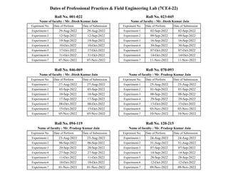
  • 1. Expriment No. Date of Perform Date of Submission Expriment No. Date of Perform Date of Submission Experiment-1 29-Aug-2022 29-Aug-2022 Experiment-1 02-Sep-2022 02-Sep-2022 Experiment-2 12-Sep-2022 12-Sep-2022 Experiment-2 09-Sep-2022 09-Sep-2022 Experiment-3 19-Sep-2022 19-Sep-2022 Experiment-3 16-Sep-2022 16-Sep-2022 Experiment-4 10-Oct-2022 10-Oct-2022 Experiment-4 30-Sep-2022 30-Sep-2022 Experiment-5 17-Oct-2022 17-Oct-2022 Experiment-5 07-Oct-2022 07-Oct-2022 Experiment-6 31-Oct-2022 31-Oct-2022 Experiment-6 14-Oct-2022 14-Oct-2022 Experiment-7 07-Nov-2022 07-Nov-2022 Experiment-7 11-Nov-2022 11-Nov-2022 Expriment No. Date of Perform Date of Submission Expriment No. Date of Perform Date of Submission Experiment-1 27-Aug-2022 27-Aug-2022 Experiment-1 25-Aug-2022 25-Aug-2022 Experiment-2 03-Sep-2022 03-Sep-2022 Experiment-2 01-Sep-2022 01-Sep-2022 Experiment-3 10-Sep-2022 10-Sep-2022 Experiment-3 08-Sep-2022 08-Sep-2022 Experiment-4 17-Sep-2022 17-Sep-2022 Experiment-4 29-Sep-2022 29-Sep-2022 Experiment-5 08-Oct-2022 08-Oct-2022 Experiment-5 13-Oct-2022 13-Oct-2022 Experiment-6 15-Oct-2022 15-Oct-2022 Experiment-6 03-Nov-2022 03-Nov-2022 Experiment-7 05-Nov-2022 05-Nov-2022 Experiment-7 10-Nov-2022 10-Nov-2022 Expriment No. Date of Perform Date of Submission Expriment No. Date of Perform Date of Submission Experiment-1 23-Aug-2022 23-Aug-2022 Experiment-1 24-Aug-2022 24-Aug-2022 Experiment-2 06-Sep-2022 06-Sep-2022 Experiment-2 31-Aug-2022 31-Aug-2022 Experiment-3 20-Sep-2022 20-Sep-2022 Experiment-3 07-Sep-2022 07-Sep-2022 Experiment-4 27-Sep-2022 27-Sep-2022 Experiment-4 14-Sep-2022 14-Sep-2022 Experiment-5 11-Oct-2022 11-Oct-2022 Experiment-5 28-Sep-2022 28-Sep-2022 Experiment-6 18-Oct-2022 18-Oct-2022 Experiment-6 12-Oct-2022 12-Oct-2022 Experiment-7 01-Nov-2022 01-Nov-2022 Experiment-7 09-Nov-2022 09-Nov-2022 Roll No. 001-022 Roll No. 046-069 Roll No. 094-119 Roll No. 023-045 Dates of Professional Practices & Field Engineering Lab (7CE4-22) Name of faculty : Mr. Pradeep Kumar Jain Roll No. 070-093 Roll No. 120-215 Name of faculty : Mr. Jitesh Kumar Jain Name of faculty : Mr. Jitesh Kumar Jain Name of faculty : Mr. Pradeep Kumar Jain Name of faculty : Mr. Jitesh Kumar Jain Name of faculty : Mr. Pradeep Kumar Jain
  • 2. Experiment - 1 Object: - To study Different types of Knots. Knots: These are the bases of branches or limbs which are broken or cut off from the tree. The portion from which the branch is removed receives nourishment from the stem for a pretty long time and it ultimately results in the formation of dark hard rings which are known as the knots. As continuity of wood fibres is broken by knots, they form a source of weakness. The knots are classified on the basis of their size and form. Classification of knots on size basis S. No. Type of knot Size 1 Pin knot Diameter upto 6.50 mm. 2 Small knot Diameter between 6.50 and 20 mm. 3 Medium knot Diameter between 20 and 40 mm 4 Large knot Diameter greater than 40 mm.
  • 3. Classification of knots on basis of form and quality. S. No. Type of knot Remarks 1 Dead knot The fibres of knot are properly interconnected with those of surrounding wood. Hence it can be easily separated out from the body of wood. It is not safe to use wood with such a knot for engineering purposes. 2 Decayed knot It is also known as an unsound knot and it is formed by the action of fungi on wood. 3 Live knot It is also known as a sound knot It is free from decay and cracks. It is thoroughly fixed in wood and hence it cannot be separated out from the body of wood. The presence of such knots makes wood difficult to plane. However the wood containing such knots can be used for engineering purposes. 4 Loose knot It indicates preliminary stage of dead knot. The fibres of knot are not firmly held in the surrounding wood. 5 Round knot The cross-section of this type of knot is either round or oval. It is obtained by cutting the knot at right angles to its long axis. 6 Tight knot It indicates preliminary stage of live knot. The fibres of knot are firmly held in the surrounding wood.
  • 4. Experiment - 2 Object: To study Site plan, index plan, layout plan, plinth area, floor area of buildings. Site Plan: - For all building plans site plans are prepared to a small scale of 1 cm = 5 m showing the orientation of the building, boundaries of land, position of roads, drain sewer line, water pipelines, and adjoining plots of lands with their ownership The North direction line is also shown on one corner of the site plan to show the geographical orientation of the building. In site plan, the building and other details are drawn in line diagram. From the site plan, location of the work with respect to the surrounding is known. Index Plan: - For Road project, Irrigation project. Water supply project, Sanitary work project, Major building project etc., an index plan to a scale 1 cm=0.5 km is prepared showing alignment with position of culverts, outlets and other main works or main outlines of the whole work so that at a glance an idea of the project may be formed. For big project the Index plan is drawn with a much small scale and is known as key plan. Layout Plan:- For a project consisting of a number of buildings and structures a Layout plan of the whole area is prepared to a small scale of 1 cm = 10 m to, 1 cm = 20 m, with all proposed buildings, structures, etc. showing their sizes, positions, locations and orientations. Besides the buildings and structures the roads, lanes, drains, pipe lines, electric lines, parks, etc. are also shown in the layout plan with their proper notations. The boundary, the main approach roads and adjoining areas with their ownership, name, nature etc., are also indicated in the layout plan. In Layout plan the details are shown in line diagram. The North direction line is also shown in one corner of the layout plan to indicate the geographical orientation of the buildings. The layout plan gives a general idea of the project at a glance. Plinth Area - Plinth area is the built up covered area of a building measured at floor level of any storey. Plinth area is calculated by taking the external dimensions of the building at the floor level excluding plinth offsets if any. Court-yard, open areas, balconies and cantilever projections are not included in the Plinth area. Supported porches (other than cantilevered) are included in the Plinth area.
  • 5. The following shall be included in the Plinth area.-(i) All floors, area of walls at the floor level excluding plinth offsets, if any, (ii) Internal shafts for sanitary installations provided these do not exceed 2 sq m in area air condition ducts, lifts etc. (iii) The area of barsati and the area of mumty at terrace level. (i) Area of porches other than cantilevered. The following shall not be included in the Plinth area. (i) Area of loft. (ii) Internal sanitary shafts provided these are more than 2 sq m in area, (iii) Unenclosed balconies (iv) Towers, turrets, domes etc. projecting above the terrace level, not forming a storey at the terrace level, (v) Architectural bands, cornices etc. (vi) Sunshades, Vertical sun breakers or box louvers projecting out. Floor Area :- Floor area of a building is the total area of floor in between walls and consists of floor of all rooms verandahs passages corridors staircase room, entrance halls, kitchen stores, bath and latrine (W. Cs.) etc. Sills of doors and openings are not included in the Floor area. Area occupied by walls, pillars, pilaster, and other intermediate supports are not included in the Floor area. In short, Floor area is equal to Plinth area minus area occupied walls. For deduction of wall area from plinth area to obtain Floor area the area shall include (i) Door and other openings in the wall. (ii) Intermediate pillars and supports, (iii) Pilasters along walls exceeding 300 sq cm in area (iv) Flues which are within walls. But the following shall be excluded from the walls area (i) Pilaster along walls not exceeding 300 sq m in area, (ii) Fire place projecting beyond the face of wall in living rooms, (iii) Chulla platforms projecting beyond the face of wall in kitchens. The floor of each storey and different types of floor should be measured and taken separately. The floor area of basement, mezzanines, barsaties, mumties, porches, etc. should be measured separately.
  • 6. Experiment - 3 Object: To study Foundation plan layout in field. Setting out or ground tracing is the process of laying down the excavation lines and centre lines etc. on the ground, before excavation is started. After the foundation design is done, a setting out plan, sometimes also known as foundation layout plan, is prepared to some suitable scale (usually 1:50). The plan is fully dimensioned. For setting out the foundations of small buildings, the centre line of the longest outer wall of the building is first marked on the ground by stretching a string between wooden or mild steel pegs driven at the ends. This line serves as reference line. For accurate work, nails can be fixed at the centre of the pegs. Two pegs, one on either side of the central peg, are driven at each end of the line. Each peg is equidistant from the central peg, and the distance between the outer pegs corresponds to the width of foundation trench to be excavated. Each peg may project about 25 to 50 mm above ground level and may be driven at a distance of about 2 m from the edge of excavation so that they are not disturbed. When string is stretched joining the corresponding pegs (say 2-2) at the two extremities of the line, the boundary of the trench to be excavated can be marked on the ground with dry lime powder. The centre lines of other walls, which are perpendicular to the long wall, are then marked by setting out right angles. A right angle can be set out by forming a triangle with 3, 4 and 5 units long. These dimensions should be measured with the help of a steel tape. Alternatively, a theodolite or prismatic compass may be used for setting out right angles. Similarly, outer lines of the foundation trench of each cross-wall can be set out, as shown in Figure. For a big project, reference pillars of masonry may be constructed as shown in Figure. These pillars may be about 20 cm thick and about 15 cm wider than the width of the foundation trench. The top of the pillars is plastered, and is set at the same level, preferably at the plinth level. Pegs are embedded in these pillars and nails are then driven in the pegs to represent the centre line and the outer lines of the trench. Sometimes, additional walls are provided to represent plinth lines.
  • 7. Figure : Setting out with the help of pegs Figure : Setting out using masonry pillars
  • 8. Experiment - 4 Object: To study Bar bending schedule as per IS 2502-1963. For guidance to the labourers / supervisors bar bending schedule is prepared. The schedule of bars is the list of reinforcement bars in the tabular form. The particulars of bars, such as diameter, shape of bending in sketches. Length of each bends length, angles of bending, total length of bars etc. are given in the bar bending schedule. While preparing estimate of reinforcement the diameter, length of bars and their length are taken directly from bar bending schedule if it is prepared along with the drawings. Following table gives the total length of few common types of reinforcement bars.
  • 9. (As per IS 2502:1963, Page-6, Note-1) k = 2 in the case of Mild Steel k = 3 in the case of Medium Tensile Steel k = 4 in the case of Cold-worked Steel (As per IS 2502-1963, Page-7, Table II) H = Hook allowance taken as 9d, 11d, 13d and 17d for k values 2, 3, 4 and 6 respectively and rounded off to the nearest 5 mm, but not less than 75 mm. B = Bend allowance taken as 5d, 5.5d, 6d and 7d for k values 2, 3, 4 and 6 respectively and rounded off to the nearest 5 mm, but not less than 75 mm.
  • 10. Experiment - 5 Object: To study Specifications of building components. Specification specifies or describes the nature and the class of the work, materials to be used in the work, workmanship, etc., and is very important for the execution of the work. The cost of a work depends much on the specifications. Specifications should be clear, and there should not be any ambiguity anywhere. From the study of the specifications one can easily understand the nature of the work and what the work shall be. Aims of specifications:- 1. The specifications clearly illustrate the quality of the materials, the workmanship desired and the method of doing the work. This enables contractor to quote the correct rates for the works. 2. As the specifications give detailed information regarding the materials and the workmanship, it serves as a guide to the contractor as well as to the supervising staff, during the construction and execution of the work. 3. The specifications protect the interest of the owner against low quality material or bad workmanship, at the same time it provides freedom to the contractors for turning out or constructing the satisfactory structures. 4. As the specifications give details regarding the quality of the materials, the contractor can arrange the same in time and complete the work within scheduled time. 5. As the cost of work directly depends on its specifications, the specifications give correct idea about the estimated cost, and funds can be arranged accordingly. General Specification of a First Class Building 1. Foundation and Plinth: - Foundation and plinth shall be of first class brick work in lime mortar or 1 : 6 cement mortar over lime concrete or 1 : 4 : 8 cement concrete. 2. Damp Proof Course: - D.P.C. shall be 2.5 cm thick cement concrete 1 : 1.5 : 3, mixed with one kg of impermo per bag of cement or other standard water proofing materials as specified and painted with two coats of bitumen. 3. Superstructure: - Superstructure shall be of first class with lime mortar or 1 : 6 cement mortar. Lintels over doors and windows shall be of R.C.C.
  • 11. 4. Roof: - Roofs shall be of R.C.C slab with an insulation layers and lime concrete terracing above, supported over R.S. joists or R.C.C beams as required. Height of rooms shall not be less than 3.7 m. 5. Flooring: - Drawing room and dining room floors shall be of mosaic. Both room and W.C floors and dado shall be of mosaic. Floors of bed rooms shall be colored and polished of 2.5 cm cement concrete over 7.5 cm lime concrete. Floors of others shall be of 2.5 cm cement concrete over 7.5 cm lime concrete polished. 6. Finishing: - Inside and outside shall be of 12 mm cement lime plastered 1 : 1 : 6 Drawing, dining and bed rooms inside shall be distempered, and others inside whitewashed 3 coats. Outside shall be coloured snowcem washed two coats over one coat of white wash. 7. Door and Windows: - Chaukhats shall be seasoned teak wood. Shutters shall be teak, wood 4.3 cm thick panelled glazed or partly penelled and partly glazed as required, with additional wire gauge shutters. All fittings shall be of brass. Doors and windows shall be varnished or painted two coats with high class enamel paints over one coat of priming. Windows shall be provided with iron gratins or grills. 8. Miscellaneous: - Rain water pipes of cast iron or of asbestos cement shall be provided and finished painted. Building shall be provided with 1st class sanitary and water fittings and electrical installation. One meter wide 7.5 cm thick C.C. 1 : 3 : 6 apron shall be provided all around the building. General Specification of a Second Class Building 1. Foundation and Plinth: - Foundation and plinth shall be of first class brick work lime mortar over lime concrete. 2. Dam Proof Course: - D.P.C. shall be 2 cm thick cement concrete 1 : 2, mixed with one kg of impermo per bag of cement or other standard water proofing materials. 3. Superstructure: - Superstructure shall be of 2nd class brickwork in lime mortar. Lintels over doors and windows shall be of R.B. 4. Roofing: - Roofs shall be of R.B slab with 7.5 cm lime concrete terracing above (or flat terraced roof supported over wooden battens and beams, or jack arch roof). Verandah roof shall be of A.C sheet or Allahabad tiles.
  • 12. 5. Flooring: - Floors shall be of 2.5 cm cement concrete over 7.5 cm lime concrete. Verandah floor shall be of brick tile or flag stone over lime concrete, finished cement painted. 6. Finishing: - Inside and outside shall be of 12 mm cement mortar plastered 1 : 6. Ceiling shall be cement plastered 1 : 3. Inside shall be white washed 3 coats, outside shall be coloured washed two coats over one coat of white wash. 7. Door and Windows: - Chaukhats shall be R.C.C or well seasoned sal wood. Shutters shall be shisham wood or deodar wood 4 cm thick, panelled, glazed or partly penelled and partly glazed as required, fitted with iron fittings. Doors and windows shall be painted two coats over one coat of priming. 8. Miscellaneous: - Rain water pipes shall be of cast iron finished painted. Electrification, sanitary and water fittings may be provided if required. General Specification of a Third Class Building 1. Foundation and Plinth: - Foundation and plinth shall be of 2nd class brick work lime mortar over lime concrete. 2. Dam Proof Course: - D.P.C. shall be 2 cm thick cement mortar 1 : 2, mixed with standard water proofing compound. 3. Superstructure: - Superstructure shall be of 2nd class brickwork in mud mortar. Door and Windows opening shall be provided with arches of 2nd class brickwork in lime mortar or with wooden planks. 4. Roofing: - Roofs shall be of mud over tiles or bricks or planks over wooden beams or of tiles or G.I sheets sloping roof. 5. Flooring: - Floors shall be of brick on edge floor over well rammed earth. 6. Finishing: - Inside and outside shall be plastered with lime mortar and white washed three coats. 7. Doors and Windows: - Chaukhats shall be salwood and shutters of chir mango or other country wood. Doors and windows shall be painted two coats with ordinary paint over one coat of priming.
  • 13. General Specification of a Fourth Class Building 1. Foundation and Superstructure: - Foundation and superstructure shall be of sundried or kutcha bricks in mud mortar. Door and windows openings shall be provided with arches of 2nd class brickwork in lime mortar or with wooden planks. Inside and outside shall be water proof mud plastered. 2. Roofing: - Roofs shall be of tiles roof over bamboo and wooden support. 3. Flooring: - Floors shall be kutcha or earthen floor finished with “gobri” washing (cow dung lepping). 4. Door and Windows: - Chaukhats shall be of chir or mango wood, or country wood.
  • 14. Experiment - 6 Object: To study Valuation of buildings and properties. Valuation is the technique of estimating or determining the fair price or value of a property such as a building, a factory, other engineering structures of various types, land, etc. By valuation the present value of a property is determined. Cost means original cost of construction of purchase, while value means the present value (saleable value) which may be higher or lower than the cost. Purpose of valuation: The main purposes of valuation are as follows: (i) Buying or Selling Property: - When it is required to buy or to sell a property, its valuation is required. (ii) Taxation: - To assess the tax of a property its valuation is required. Taxes may be Municipal Tax, Wealth Tax, Property Tax, etc., and all the taxes are fixed on the valuation of the property. (iii) Rent fixation: - In order to determine the rent of a property, valuation is required. Rent is usually fixed on certain percentage of the amount of valuation (6% to 10% of the valuation). (iv) Security of Loans or Mortgage. When loans are taken against the security of the property, its valuation is required. (v) Compulsory acquisition: - Whenever a property is acquired by law compensation is paid to the owner. To determine the amount of compensation valuation of the property is required. (vi) Valuation of a property is also required for Insurance, Betterment Charges, Speculations etc. Gross income. - Gross income is the total income and includes all receipts from various sources the outgoings and the operational and collection charges are not deducted. Net income or Net return: - This is the saving or the amounts left after deducting all outgoings, operational and collection expenses from the gross income or total receipt. Net income = Gross income - outgoings
  • 15. Outgoings: - Outgoings or the expenses which are required to be incurred to maintain the revenue of the building. The various types of outgoings are taxes, repairs, management and Collection charges, sinking fund, loss of rent etc. Sinking Fund: - A certain amount of the gross rent is set aside annually as sinking fund to accumulate the total cost of construction when the life of the building is over. This Annual sinking fund is also taken as outgoings. Loss of rent: - The property may not be kept fully occupied in such a case a suitable amount should be deducted from the gross rent under outgoings. Scrap value: - Scrap value is the value of dismantled materials. For a building when the life is over at the end of its utility period the dismantled materials as steel, bricks, timber, etc., will fetch a certain amount which is the scrap value of the building. In the case of machine the scrap value is the value of the metal only or the value of the dismantled parts. The scrap value of a building may be about 10 per cent of its total cost of construction. The cost of dismantling and removal of the rubbish material is deducted from the total receipt from the sale of the useable materials to get the scrap value. Salvage value: - It is the value at the end of the utility period without being dismantled. A machine after the completion of its usual span of life or when it become- uneconomic, may be sold and one may purchase the same for use for some other purpose, the sale value of the machine is the salvage value. It does not include the cost of removal, sale, etc. Normally, the scrap value, or the salvage value of a property or an asset has got some positive figure, but it may also be zero or negative. As for example the scrap value or a R.C.C. structure will be negative, as dismantling and removal will be costly. Market value: - The Market value of a property is the amount which can be obtained at any particular time from the open market if the property is put for sale. The market value will differ from time to time according to demand and supply. The market value also changes from time to time for various miscellaneous reasons such as changes in industry, changes on fashions, means of transport, cost of materials and labour, etc. Rateable value: - Rateable value is the net annual letting value of a property, which is obtained after deducting the amount of yearly repairs from the gross income. Municipal and other taxes are charged at a certain percentage on the ratable value of the property. Obsolescence:- The value of property or structures become less by its becoming out of date in style, in structure in design, etc., and this is termed as Obsolescence. An old dated building
  • 16. with massive walls, arrangements of rooms not suited in present days and for similar reasons, becomes obsolete even if it is maintained in a very good condition, and its value becomes less due to obsolescence. Annuity:- Annuity is the annual periodic payments for repayments of the capital amount invested by a party. These annual payments are either paid at the end of the year or at the beginning of the year, usually for a specified number of years. If the amount of annuity is paid for a definite number of periods or years, it is known as Annuity certain. In such cases the amount of annuity will be higher, the lesser the number of the years the higher will be the amount and vice versa to clear up to the whole amount of capital. If the amount of annuity is paid at the beginning of each period of year and payments continued for definite number of periods, it is known as Annuity due. If the payment of annuity begins at some future date after a number of years, this is known as Deffered Annuity. If the payments of annuity continue for indefinite period, it is known as Perpetual Annuity. Though annuity means annual payment, the amount of annuity may be paid by twelve monthly installments or quarterly or half-yearly installments. Capital cost: - Capital cost is the total cost of construction including land, or the original total amount required to possess a property. It is the original cost and does not change, while value of a property is the present cost which may be calculated by methods of valuation. Capitalized value: - The Capitalized value of a property is the amount of money whose annual interest at the highest prevailing rate of interest will be equal to the net income from the property. To determine the capitalized value of a property it is required to know the net income from the property and the highest prevailing rate of interest. Year's purchase (Y.P.).: -Year's purchase is defined as the capital sum required to be invested in order to receive an annuity Re 1.00 at a certain rate of interest. Year's purchase = 1 i+s
  • 17. where i = Rate of interest in decimal s= sinking fund to replace Re. 1.00 at the end of the given period. Sinking fund: - The fund which is gradually accumulated by way of periodic on annual deposit for the replacement of the building or structure at the end of its useful life is termed as sinking fund. The object of creating sinking fund is to accumulate sufficient money to meet the cost of construction or replacement of the building or structure after its utility period. The amount of annual installment of the Sinking fund may be found out by the formula: I = Si (1+i)n − 1 where S = total amount of Sinking fund to be accumulated n = number of years required to accumulate the Sinking fund I = rate of interest in decimal Depreciation: - Depreciation is the gradual exhaustion of the usefulness of a property. This may be defined as the decrease or loss in the value of a property due to structural deterioration use, life wear and tear, decay and obsolescence. The value of a building or structure will be gradually reduced due to its use, life, wear and tear, etc., and a certain percentage of the total cost may be allowed as depreciation to determine its present value. Usually a percentage on depreciation per annum is allowed. Methods of valuation of Building 1. Rental method of valuation:- In this method, the net income by way of rent is found out by deducting all outgoings from the gross rent. This method is applicable only when the rent is known or probable rent is determined by enquiries. 2. Direct comparison with the capital value:- This method may be adopted when the rental value is not available from the property concerned, but there are evidences of sale price of properties as a whole. 3. Valuation based on profit:- This method of valuation is suitable for buildings like hotels, cinemas, theatres, etc. for which the capitalized value depends on the profit.
  • 18. 4. Valuation based on cost: - In this method the actual cost incurred in constructing the building or in possessing the property is taken as basis to determine the value of property. 5. Development method of valuation: - This method of valuation is used for the properties which are in the undeveloped stage or partly developed and partly undeveloped stage. If a building is required to be renovated by making additions, alterations or improvements, the development method of valuation may be used. 6. Depreciation method of valuation: - According to this method of valuation the building should be divided into four parts viz. (i) Walls, (ii) Roofs, (iii) Floor and (iv) Doors and windows and the cost of each part should first be worked out on the present-day rates by detailed measurements.
  • 19. Experiment - 7 Object: To study Work at heights – scaffolding and ladders use, type of scaffolds, design and load factors, defects and inspection norms, type of ladders, upkeep, defects and good maintenance tips. Scaffolding As per IS : 3696 ( Part 1 ) – 1987, (Reaffirmed 2002, 2012, 2017) : (Clause 2.1, Page 6) A temporary structure consisting of standards, putlogs, ledgers, generally of bamboo, ballies, timber or metal to provide a working platforms for workmen and materials in the course of construction, maintenance, repairs and demolition, and also to support or allow hoisting and lowering of workmen, their tools and materials. As per IS : 3696 ( Part 2 ) – 1987, (Reaffirmed 2002, 2012, 2017) : (Clause 0.3, Page 3) Scaffolds are essential construction equipments which offer in them temporary platforms for carrying out all those works which cannot be conveniently and easily carried out either from ground floor or from any other floor of the building or even with the use of a ladder. Types of Scaffolding: Scaffoldings can be of the following types: (i) Single scaffolding or brick-layers scaffolding: - This scaffolding is commonly used for bricklaying and also called putlog scaffolding. Figure: - Typical sketch illustrating components of a single scaffold
  • 20. (ii) Double scaffolding or masons scaffolding: - It is useful in stone masonry work and also called independent scaffolding. Figure: - Typical sketch of independents scaffold (iii) Cantilever/ Outrigger/ Needle scaffolding:- It is useful when ground is weak to support conditions, construction of the upper part of the wall is to be carried out etc. Figure: - The cantilever Scaffold (iv) Suspended scaffolding: - It is light weight and used for repair works as pointing and painting etc.
  • 21. Figure:- Suspended Scaffolding (v) Trestle scaffolding:- It is used for repair work inside the building at upto the height of 5.0 m. Figure:- Trestle Scaffolding (vi) Steel scaffolding:- It is very fast in installation and erection. (vii) Patented scaffolding:- It is available in market and adjustable at several heights as per requirements.
  • 22. General safety requirements for scaffolds: As per IS : 3696 ( Part 1 ) – 1987, (Reaffirmed 2012, 2017) : (Clause 9, Page 29) (i) Scaffolds shall be provided for all work that cannot be safely performed from the ground, or from solid construction. Every scaffold and every part thereof including supports shall be of good construction, suitable and sound material and having adequate strength for the purpose for which it is used. It shall be properly maintained. Construction and dismantling of every scaffold shall be under the supervision of a competent authority. (ii) The erection, alterations and removal should be done only under the supervision of men who are thoroughly experienced in this work. (iii) The use of barrels, boxes, loose tile blocks or other unsuitable objects as supports for working platforms shall not be permitted. (iv) Every scaffold shall be securely supported or suspended and shall, where necessary, be sufficiently and properly strutted or braced to ensure stability. The use of cross braces or framework as means of access to the working surface shall not be permitted. (v) Every platform, gangway, run or stairs shall be kept free from any unnecessary obstruction, material, rubbish and projecting rails, when they become slippery, appropriate steps shall be taken by way of sanding, cleaning or otherwise to remedy the defect. (vi) Each supporting member used in .the construction of runways, platforms, ramps and scaffolds shall be securely fastened and braced. The supporting member shall be placed on a firm, rigid, smooth foundation of a nature that will prevent lateral displacement. All fasteners and anchorages shall be inspected by a competent person. (vii) Where planks are butt-jointed, two parallel putlogs shall be used not more than 100 mm apart, giving each plank sufficient support. Nails shall penetrate to the holding piece to a depth of at least 12 times the diameter of the nail. (viii) If scaffolds are to be used to a great extent or for a long period of time, a regular plank stairway wide enough to allow two people to pass shall be erected. Such stairways shall have handrails on both sides.
  • 23. (ix) A scaffold platform plank shall not project beyond its end supports to a distance exceeding four times the thickness of the plank unless it is effectively secured to prevent tipping. Cantilever of scaffold planks shall be avoided. Ledgers or putlog should be erected to support the ends of such planks. (x) All scaffolds or working platforms of any nature shall be securely fastened to the building or structure; if independent of the building, they shall be braced or guyed properly. (xi) Grease, mud, paint gravel or plaster or any such hazardous substances shall be removed from scaffolds immediately. To prevent slipping on the platforms, either sand or saw dust or other suitable material shall be spread. (xii) Men shall not be allowed to work from scaffolds during storms or high winds. After heavy rains or storm, the scaffolds should be inspected by the site-in-charge. Scaffolds should also be inspected every fortnight, during use, by him and again before starting use. Where the joints or members are found defective, the joint should be set right and member replaced. (xiii) In case both light and heavy duty scaffolds are used in close vicinity, conspicuously placed notice boards shall indicate the light duty scaffolds and the limits on their usages. (xiv) Safety codes should be strictly followed. Standard safety requirements are just as important for temporary structures as they are for permanent structures. Inspection of scaffolds (IS 4014-2 : 2013, Clause 7, Page 1) (i) Subject to provisions of this standard, the scaffold shall be inspected by qualified and authorized engineer, a) immediately after erection; b) before every use; and c) at regular period and wherever there is any adverse climatic occurrence such as weather conditions likely to have affected or displaced any part. A report of the results of such inspection certifying that the scaffold is suitable for use signed by the person making the inspection shall be entered into a register to be kept at the worksite. It shall not require a scaffold to be inspected by reason only that it has been added to, altered or partly dismantled.
  • 24. (ii) The requirement of (i) (a) and (i) (b) shall not apply in the case of a scaffold no part of which has been erected for more than seven days, and the requirement of reporting of the results shall not apply to a ladder scaffold, a trestle scaffold or a scaffold from no part of which a person is liable to fall more than 2.0 m Ladders As per IS 3696 (Part 2 ) – 1991, (Reaffirmed 2002, 2012, 2017) : (Clause 3.1, Page 1) An appliance or equipment usually consisting of two side rails joined together at regular intervals with cross pieces like steps, rungs or cleats and used in ascending or descending between two points at different levels. Classification of ladders (IS 3696-2 : 1991, Clause 4, Page 1) (i) Built-Up Ladders (ii) Portable Ladders of Rigid Construction (iii) Stock ladders (iv) Extension ladders (v) Sectional ladders (vi) Step ladders (vii)Trestle ladders (viii) Extension trestle ladders (ix) Rope Ladders Inspection of ladders (IS 3696-2: 1991, Clause 8, Page 4) : (i) Wooden ladders shall be inspected at least once in a week for damage and deterioration. Ladders longer than 5 m length require more caution inspection. Close visual inspection is recommended in preference to load testing. (ii) Metal ladders shall be inspected at least once in three months and all parts checked for wear, corrosion and structural failure. (iii) All ladders shall be carefully inspected, if incidentally dropped or otherwise damaged in use. (iv) Rope ladders shall be tested at least once a month.