Recommended

Recommended
More Related Content
Similar to poster presentation, Muhammad Usman.pptx
Similar to poster presentation, Muhammad Usman.pptx (20)
More from MuhammadUsman854361
Recently uploaded
Recently uploaded (20)
poster presentation, Muhammad Usman.pptx
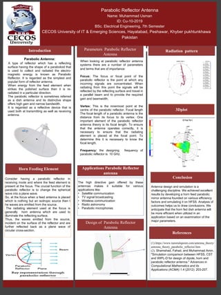
- 1. SQUARE MICROSTRIP PATCH ANTENNA Umair CU-169-2016C BS.c Electrical Engineering, 7th Semester CECOS UNIVERSITY KHYBER PAKHTUNKHWA, PESHAWAR, PHASE 6 HAYATABAD Introduction Construction and Working ⮚The microstrip consists of a very thin metallic strip or patch placed on a ground plane with a dielectric material in-between. ⮚The radiating element and feed lines are placed by the process of photo- etching on the dielectric material. ⮚The patch or microstrip is chosen to be square, circular or rectangular in shape for the ease of analysis and fabrication Disadvantages ⮚It offers low efficiency due to dielectric losses and conductor losses. ⮚It offers lower gain. ⮚It has higher level of cross polarization radiation. ⮚It has lower power handling capability. ⮚It has inherently lower impedance bandwidth. ⮚The microstrip antenna structure radiates from feeds and other junction points. Advantages ⮚Smaller in size. ⮚They are easy to fabricate and comfortable on curved parts of the device. ⮚The microstrip patches of various shapes e.g. rectangular, square, triangular etc. are easily etched. ⮚They have lower fabrication cost and hence they can be mass manufactured. ⮚They are capable of supporting multiple frequency bands (dual, triple). ⮚They support dual polarization types viz. linear and circular both. ⮚They are light in weight. Application ⮚Used in Space craft applications ⮚Used in Air craft applications ⮚Used in Telemedicine. ⮚Used in Mobile and satellite communication. The Micrstrip patch antenna Model versus Reality is shown the model was designed in HFSS and then it is printed. Square Patch Antenna Simulation ⮚The length of the metal patch should be λ/2. ⮚When the antenna is excited, the waves generated within the di-electric undergo reflections and the energy is radiated from the edges of the metal patch which is very low. Parabolic Reflector Antenna Name: Muhammad Usman ID: Cu-10-2019 BSc. Electrical Engineering, 7th Semester CECOS University of IT & Emerging Sciences, Hayatabad, Peshawar, Khyber pukhtunkhawa Pakistan i Parabolic Antenna: A type of reflector which has a reflecting surface having the shape of a paraboloid that is used to collect and radiated the electro- magnetic energy is known as Parabolic Reflector. It is regarded as the simplest and popular form of reflector antenna. When energy from the feed element when strikes the polished surface then it is re- radiated in a particular direction. The parabolic reflector is sometimes referred as a dish antenna and its distinctive shape offers high gain and narrow bandwidth. It is regarded as a reflective device that is used both at transmitting as well as receiving antenna. (1).https://www.tutorialspoint.com/antenna_theory/ antenna_theory_parabolic_reflector.htm (2). Shamshad, Fahad, and Muhammad Amin. "Simulation comparison between HFSS, CST and WIPL-D for design of dipole, horn and parabolic reflector antenna." Advances in Computational Mathematics and its Applications (ACMA) 1.4 (2012): 203-207. Antenna design and simulation is a challenging discipline. We achieved excellent results by developing a horn feed parabolic mirror antenna founded on various efficiency factors and simulating it on HFSS. Analysis of outcomes helps us to draw conclusions. We anticipate that the horn fed dish antenna will be more efficient when utilized in an application based on an examination of the major parameters. 3Dplot Consider having a parabolic reflector in receiving mode and where the feed element is present at the focus. The crucial function of the parabolic reflector is to change the spherical wave into a plane wave. So, at the focus when a feed antenna is placed which is nothing but an isotropic source then t he waves are emitted from the source. The radiating element used at the focus is generally horn antenna which are used to illuminate the reflecting surface. Thus, the waves emitted from the source, incident on the surface of the reflector and are further reflected back as a plane wave of circular cross-section. Radiation pattern Introduction Applications Parabolic Reflector antenna Horn Feeding Element Conclusion: References: The high directive gain offered by these antennas makes it suitable for various applications like: • Satellite communication • TV signal broadcasting • Wireless communication • Radio astronomy • Parabolic microphones Design of Parabolic Reflector Antenna Parameters Parabolic Reflector Antenna When looking at parabolic reflector antenna systems there are a number of parameters and terms that are of importance: Focus: The focus or focal point of the parabolic reflector is the point at which any incoming signals are concentrated. When radiating from this point the signals will be reflected by the reflecting surface and travel in a parallel beam and to provide the required gain and beamwidth. Vertex: This is the innermost point at the centre of the parabolic reflector. Focal length The focal length of a parabolic antenna is the distance from its focus to its vertex. One important element of the parabolic reflector antenna theory is its focal length. To ensure that the antenna operates correctly, it is necessary to ensure that the radiating element is placed at the focal point. To determine this it is necessary to know the focal length. Frequency: the designing frequency of parabolic reflector is 10 GHz.