![Nimonic alloy 80A followed, an alloy widely used in engine valves today. Progressively stronger
alloys were subsequently developed: Nimonic alloy 90 (1945), Nimonic alloy 100 (1955), and
Nimonic alloys 105 (1960) and 115 (1964 - ProfJohn Gittus FREng. DSc. D Tech 1986.)
PROPERTIESAND USES
Due to its ability to withstand very high temperatures, Nimonic is ideal for use in aircraft
parts and gas turbine components such as turbine blades and exhaust nozzles on jet
engines, for instance, where the pressure and heat are extreme. It is available in different
grades, including Nimonic 75, Nimonic 80A, and Nimonic 90.[4][5] Nimonic 80a was used for
the turbine blades on the Rolls-Royce Nene and de Havilland Ghost, Nimonic 90 on the
Bristol Proteus, and Nimonic 105 on the Rolls-Royce Spey aviation gas turbines. Nimonic
263 was used in the combustion chambers of the Bristol Olympus used on the Concorde
supersonic airliner.
Nimonic 75 has been certified by the European Union as a standard creep reference
material.alloy 75 (UNS N06075/W.Nr. 2.4951&2.4630) is an80/20 nickel-chromium
alloywith controlledadditions oftitanium andcarbon. First introducedinthe 1940sfor
turbine blades intheprototype Whittlejet engines, it is now mostlyusedfor sheet
applications calling for oxidationandscaling resistance coupledwithmedium strength
at high
operating temperatures. It is still usedingas turbine engineering andalso for industrial
thermal processing, furnace componentsandheat-treatment equipment. It is readily
fabricatedand welded.
METALLOGRAPHY
NIMONIC alloy75 has a stable, austenitic, solidsolutionatall temperaturesbelow the
solidus and, apart from recrystallizationand graingrowth, is unaffectedby heat
treatment. Typically, three phases are visible:
1) Oxide or silicate inclusions that arise from de-oxidation ofthe moltenmetal, visible
inthe polishedconditionas small, darkinclusions frequentlypresent as stringers
orientedinthe principle workingdirection.
2) Intergranularlyoccurring primarycarbides, nitrides or carbonitrides ofthe general
type M(CN) where M is usuallytitanium. They are visible inthe polished
conditionas substantiallyequiaxed, roughlyspherical o rcuboidinclusions whosecolor
varies from whiteto purple for the carbide, to yellow for the nitride.
3) Chromium-richgrainboundarycarbides, usuallyofthe
type M23C6. The carbides willdissolve intothe matrix withheat, but at a temperature
much higher thanthe normal annealing temperature.
Suitable etchesfor NIMONIC alloy75 are:
1) A 4% aqueous solutionofsulfuric acidused electrolyticallyat approximately4V.](data:image/gif;base64,R0lGODlhAQABAIAAAAAAAP///yH5BAEAAAAALAAAAAABAAEAAAIBRAA7)
Recommended
More Related Content
What's hot
What's hot (20)
Similar to Study of nimonic 75 alloy
Similar to Study of nimonic 75 alloy (20)
More from Mainak Saha(मैनक साहा)
More from Mainak Saha(मैनक साहा) (11)
Recently uploaded
Recently uploaded (20)
Study of nimonic 75 alloy
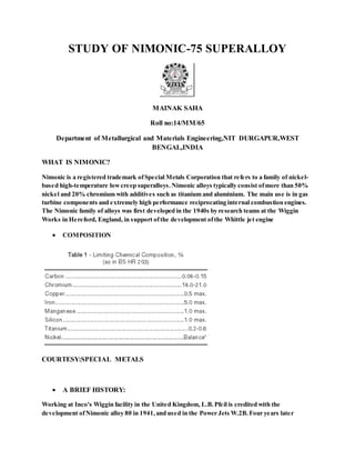
- 1. STUDY OF NIMONIC-75 SUPERALLOY MAINAK SAHA Roll no:14/MM/65 Department of Metallurgical and Materials Engineering,NIT DURGAPUR,WEST BENGAL,INDIA WHAT IS NIMONIC? Nimonic is a registered trademark ofSpecial Metals Corporation that refers to a family of nickel- based high-temperature lowcreep superalloys.Nimonic alloys typically consist ofmore than 50% nickel and 20% chromium with additives such as titanium and aluminium. The main use is in gas turbine components and extremely high performance reciprocating internal combustion engines. The Nimonic family of alloys was first developed in the 1940s by research teams at the Wiggin Works in Hereford, England, in support ofthe development ofthe Whittle jet engine COMPOSITION COURTESY:SPECIAL METALS A BRIEF HISTORY: Working at Inco's Wiggin facility in the United Kingdom, L.B.Pfeil is credited with the development ofNimonic alloy 80 in 1941,and used in the Power Jets W.2B.Four years later
- 2. Nimonic alloy 80A followed, an alloy widely used in engine valves today. Progressively stronger alloys were subsequently developed: Nimonic alloy 90 (1945), Nimonic alloy 100 (1955), and Nimonic alloys 105 (1960) and 115 (1964 - ProfJohn Gittus FREng. DSc. D Tech 1986.) PROPERTIESAND USES Due to its ability to withstand very high temperatures, Nimonic is ideal for use in aircraft parts and gas turbine components such as turbine blades and exhaust nozzles on jet engines, for instance, where the pressure and heat are extreme. It is available in different grades, including Nimonic 75, Nimonic 80A, and Nimonic 90.[4][5] Nimonic 80a was used for the turbine blades on the Rolls-Royce Nene and de Havilland Ghost, Nimonic 90 on the Bristol Proteus, and Nimonic 105 on the Rolls-Royce Spey aviation gas turbines. Nimonic 263 was used in the combustion chambers of the Bristol Olympus used on the Concorde supersonic airliner. Nimonic 75 has been certified by the European Union as a standard creep reference material.alloy 75 (UNS N06075/W.Nr. 2.4951&2.4630) is an80/20 nickel-chromium alloywith controlledadditions oftitanium andcarbon. First introducedinthe 1940sfor turbine blades intheprototype Whittlejet engines, it is now mostlyusedfor sheet applications calling for oxidationandscaling resistance coupledwithmedium strength at high operating temperatures. It is still usedingas turbine engineering andalso for industrial thermal processing, furnace componentsandheat-treatment equipment. It is readily fabricatedand welded. METALLOGRAPHY NIMONIC alloy75 has a stable, austenitic, solidsolutionatall temperaturesbelow the solidus and, apart from recrystallizationand graingrowth, is unaffectedby heat treatment. Typically, three phases are visible: 1) Oxide or silicate inclusions that arise from de-oxidation ofthe moltenmetal, visible inthe polishedconditionas small, darkinclusions frequentlypresent as stringers orientedinthe principle workingdirection. 2) Intergranularlyoccurring primarycarbides, nitrides or carbonitrides ofthe general type M(CN) where M is usuallytitanium. They are visible inthe polished conditionas substantiallyequiaxed, roughlyspherical o rcuboidinclusions whosecolor varies from whiteto purple for the carbide, to yellow for the nitride. 3) Chromium-richgrainboundarycarbides, usuallyofthe type M23C6. The carbides willdissolve intothe matrix withheat, but at a temperature much higher thanthe normal annealing temperature. Suitable etchesfor NIMONIC alloy75 are: 1) A 4% aqueous solutionofsulfuric acidused electrolyticallyat approximately4V.
- 3. 2) Fry’s Reagent (4 g cupric chloridedissolvedin20 cm3 concentratedhydrochloric acidand 20 cm3water). HEAT TREATMENT For bar:30-60 minutesat 1050°C (1920°F) followedby air cooling. For sheet 5-10minutes at 1050°C (1920°F) followedby air coolingor, before welding, 5- 10 min/1050°C(1920°F)/AC + an optional 10min/1050°C(1920°F)/AC COLD WORKING The goodductilityand malleabilityofannealedNIMONICalloy75 make it amenable to many methods ofcold deformation. The alloyissubject to rapidstrainhardening. Because ofthis increasedstrength, largereductions canbe made without rupture. WELDING Material shouldbe inthe annealedcondition beforewelding althoughasmall amount of cold workistolerable. The amount of permissiblecoldworkvaries withthe component designbut simplebending and rollingoperations neednot involve re- annealing prior to welding. The heat-affected zone producedinNIMONIC alloy75 does not introduce weld decayand post-weldheat- treatment isnot, normally, necessary. If
- 4. equipment is requiredfor serviceincontact withcausticsoda, fluosilicates, or some mercurysalts, astress-relieving treatment couldbe desirable.NIMONIC alloy75 canbe weldedbythe MMA, TIG, MIG and submerged-arc processes. Matchedcomposition welding consumables are availablefrom Special MetalsWelding Products Co. The alloyis also amenable to electronbeam, oxy-acetylene andresistance welding, and to brazing and soldering. PHYSICAL AND MECHANICAL PROPERTIES: Some physical properties for NIMONIC alloy75 are giveninTables . Thermal expansiondata inTable were determinedonfullyheat-treatedmaterial. The data are subject to a variationofapproximately±5% according to processing variables. The dynamic modulus data inTable 4 were obtainedfrom fullyheat-treatedcylindrical specimens vibrated inthe flexural mode. The recommendedheat treatmentsare quotedin the Heat Treatment sectionofthis bulletin. Creep-rupture properties are shownbyLarson-MillerpresentationinFigure For all these tests, bar material was heat-treatedfor30-60 minutesat 1050°C (1920°F) andair-cooled, and sheet material was heat-treatedfor 5-10minutes at 1050°C (1920°F) andair-cooled. COURTESY:SPECIAL METALS
- 6. RESULTS OF STRESS-RELAXATION TEST
- 7. CORROSION RESISTANCE Oxidationresistance dataare presentedinTables 5 and 6, and in Figure 4. For the continuous heating tests the specimenswere oxidizedinstill air andthe weight loss was determinedafter descaling electrolyticallyinNaOH. *Cooled to room temperature after every 24 hrs
- 8. No of cycles of operation MECHANISMS OF STRENGTHENING
- 9. Courtesy:HKDH BHADESHIA,CAMBRIDGE UNIVERSITY The Ni-Al-Ti ternary phase diagrams show the γ and γ' phase field. For a given chemical composition, the fraction of γ' decreases as the temperature is increased. This phenomenon is used in order to dissolve the γ' at a sufficiently high temperature (a solution treatment) followed by ageing at a lower temperature in order to generate a uniform and fine dispersion of strengthening precipitates. The γ-phase is a solid solution with a cubic-F lattice and a random distribution of the different species of atoms. Cubic-F is short for face-centred cubic. By contrast, γ' has a cubic-P (primitive cubic) lattice in which the nickel atoms are at the face-centres and the aluminium or titanium atoms at the cube corners. This atomic arrangement has the chemical formula Ni3Al, Ni3Ti or Ni3(Al,Ti). However, as can be seen from the (γ+γ')/γ' phase boundary on the ternary sections of the Ni, Al, Ti phase diagram, the phase is not strictly stoichiometric. There may exist an excess of vacancies on one of the sublattices which leads to deviations from stoichiometry; alternatively, some of the nickel atoms might occupy the Al sites and vice-versa. In addition to aluminium and titanium, niobium, hafnium and tantalum partition preferentially into γ'. The γ phase forms the matrix in which the γ' precipitates. Since both the phases have a cubic lattice with similar lattice parameters, the γ' precipitates in a cube-cube orientation relationship with the γ. This means that its cell edges are exactly parallel to corresponding edges of the γ phase. Furthermore, because their lattice parameters are similar, the γ' is coherent with the γ when the precipitate size is small. Dislocations in the γ nevertheless find it difficult to penetrate γ', partly because the γ' is an atomically ordered phase. The order interferes with dislocation motion and hence strengthens the alloy. The small misfit between the γ and γ' lattices is important for two reasons. Firstly, when combined with the cube-cube orientation relationship, it ensures a low γ/γ' interfacial energy. The ordinary mechanism of precipitate coarsening is driven entirely by the minimisation of total interfacial energy. A coherent or semi-coherent interface therefore makes the microstructure stable, a property which is useful for elevatedtemperature applications. The magnitude and sign of the misfit also influences the development of microstructure under the influence of a stress at elevatedtemperatures. The misfit is said to be positive when the γ' has a larger lattice parameter than γ. The misfit can be controlled by altering the chemical composition, particularly the aluminium to titanium ratio. A negative misfit stimulates the formation of rafts of γ', essentially layers of the phase in a direction normal to the applied stress. This can help reduce the creep rate if the mechanism involves the climb of dislocations across the precipitate rafts. The transmission electron micrographs shown below illustrate the large fraction of γ', typically in excess of 0.6, in turbine blades designed for aeroengines, where the metal experiences temperatures in excess of 1000oC. Only a small fraction (0.2) of γ' is needed
- 10. when the alloy is designed for service at relatively low temperatures (750oC) and where welding is used for fabrication. Crystal structure of γ Transmission electron micrograph Transmission electron micrograph showing a small fraction of spheroidal γ' prime particles in a γ matrix. Ni-20Cr-2.3Al-2.1Ti-
- 11. showing a large fraction of cuboidal γ' particles in a γ matrix. Ni-9.7Al- 1.7Ti-17.1Cr-6.3Co- 2.3W at%. Hillier, Ph.D. Thesis, University of Cambridge, 1984. 5Fe-0.07C-0.005 B wt%. Also illustrated are M23C6 carbide particles at the grain boundary running diagonally from bottom left to top right. Strength versus Temperature The strength of most metals decreases as the temperature is increased, simply because assistance from thermal activation makes it easierfor dislocations to surmount obstacles. However, nickel based superalloys containing γ', which essentially is an intermetallic compound based on the formula Ni3(Al,Ti), are particularly resistant to temperature. Ordinary slip in both γ and γ' occurs on the {111}<110>. If slip was confined to these planes at all temperatures then the strength would decrease as the temperature is raised. However, there is a tendency for dislocations in γ' to cross-slip on to the {100} planes where they have a lower anti-phase domain boundary energy. This is because the energy decreases with temperature. Situations arise where the extended dislocation is then partly on the close-packed plane and partly on the cube plane. Such a dislocation becomes locked, leading to an increase in strength. The strength only decreases beyond about 600oC whence the thermal activation is sufficiently violent to allow the dislocations to overcome the obstacles. To summarise, it is the presence of γ' which is responsible for the fact that the strength of nickel based superalloys is relatively insensitive to temperature. The yield strength of a particular superalloy containing only about 20% of γ'. The points are measured and the curve is a theoretical prediction. Notice how the strength is at first insensitive to temperature.
- 12. When greater strength is required at lower temperatures (e.g. turbine discs), alloys can be strengthened using another phase known as γ''. This phase occurs in nickel superalloys with significant additions of niobium (Inconel 718) or vanadium; the composition of the γ'' is then Ni3Nb or Ni3V. The particles of γ'' are in the form of discs with (001)γ''||{001}γ and [100]γ''||<100>γ The crystal structure of γ'' is based on a body-centred tetragonal lattice with an ordered arrangement of nickel and niobium atoms. Strengthening occurs therefore by both a coherency hardening and order hardening mechanism. The lattice parameters of γ'' are approximately a=0.362 nm and c=0.741 nm X-ray Powder Diffraction A comparison of the diffraction patterns indicated below reveals many more peaks from the γ'. The additional reflections are quite weak in intensity. They arise because the γ' lattice is primitive cubic, which means that planes such as {100} give rise to diffracted intensity, whereas the reflections from the corresponding {100} planes of γ have zero intensity (destructive interference with the {200} planes). The additional reflections from the γ' prime are termed superlattice reflections and are weak because they depend on the difference in scattering power between the Ni and Al atoms.
- 13. X-ray diffracti on pattern from γ, for a particula r set of diffracti on conditio ns. X-ray diffracti on pattern from γ', for a particula r set of diffracti on conditio ns. Electron Diffraction The figures below show a superimposed electron diffraction pattern from γ, γ' and M23C6 carbide. The γ and γ' phases have their cubic- lattice edges perfectly aligned.
- 14. Alloy Compositions Commercial superalloys contain more than just Ni, Al and Ti. Chromium and aluminium are essential for oxidation resistance
- 15. small quantities of yttrium help the oxide scale to cohere to the substrate. Polycrystalline superalloys contain grain boundary strengthening elements such as boron and zirconium, which segregate to the boundaries. The resulting reduction in grain boundary energy is associatedwith better creep strength and ductility when the mechanism of failure involves grain decohesion. There are also the carbide formers (C, Cr, Mo, W, C, Nb, Ta, Ti and Hf). The carbides tend to precipitate at grain boundaries and hence reduce the tendency for grain boundary sliding. Elements such as cobalt, iron, chromium, niobium, tantalum, molybdenum, tungsten, vanadium, titanium and aluminium are also solid-solution strengtheners, both in γ and γ'. There are, naturally, limits to the concentrations that can be added without inducing precipitation. It is particularly important to avoid certain embrittling phases such as Laves and Sigma. There are no simple rules governing the critical concentrations; it is best to calculate or measure the appropriate part of a phase diagram. Alloying element effects in nickel based superalloys. The "M" in M23C6 stands for a mixture of metal atoms. Click on chart to enlarge.
- 16. Nominal chemical compositions, wt%. MA/ODS ≡ mechanically alloyed, oxide dispersion-strengthened. PM ≡ powder metallurgical origin. The alloy names are proprietary. SX ≡ single crystal. The single-crystal superalloys are often classified into first, second and third generation alloys. The second and third generations contain about 3 wt% and 6wt% of rhenium respectively. Rhenium is a very expensive addition but leads to an improvement in the creep strength. It is argued that some of the enhanced resistance to creep comes from the promotion of rafting by rhenium, which partitions into the γ and makes the lattice misfit more negative. Atomic resolution experiments have shown that the Re occurs as clusters in the γ phase. It is also claimed that rhenium reduces the
- 17. overall diffusion rate in nickel based superalloys. The properties of superalloys deteriorate if certain phases known as the topologically close-packed (TCP) phases precipitate. In these phases, some of the atoms are arranged as in nickel, where the close-packed planes are stacked in the sequence ...ABCABC.. However, although this sequence is maintained in the TCP phases, the atoms are not close-packed, hence the adjective 'topologically'. TCP phases include σ and μ. Such phases are not only intrinsically brittle but their precipitation also depletes the matrix from valuable elements which are added for different purposes. The addition of rhenium promotes TCP formation, so alloys containing these solutes must have their Cr, Co, W or Mo concentrations reduced to compensate. It is generally not practical to remove all these elements, but the chromium concentration in the new generation superalloys is much reduced. Chromium does protect against oxidation, but oxidation can also be prevented by coating the blades. ORDER STRENGTHENING OF NIMONIC 75 This is caused due to dissociation of gamma prime ppts on dislocations leading to formation of APB(anti –phase boundaries) between Ni-Ni and Al-Al or Ti-Ti sublattices. Microstructure and Heat Treatment To optimise properties (often of a coating--metal system), nickel based superalloys are, after solution treatment, heat treated at two different temperatures within the γ/γ' phase field. The higher temperature heat treatment precipitates coarser particles of γ'. The second lower temperature heat treatment leads to further precipitation, as expected from the phase diagram. This latter precipitation leads to a finer, secondary dispersion of γ'. The net result is a bimodal distribution of γ', as illustrated in this figure (courtesy R. J. Mitchell).
- 18. Oxide Dispersion Strengthened Superalloys Oxide dispersion strengthened superalloys can be produced starting from alloy powders and yttrium oxide, using the mechanical alloying process. The yttria becomes finely dispersed in the final product. It is also a very stable oxide, making the material particularly suitable for elevatedtemperature applications. However, mechanical alloying is a very difficult process so such alloys have limited applications. A transmission electron micrograph showing the oxide dispersion in a mechanically-alloyed nickel based superalloy is shown below. ODS alloy MA6000 Applications of nickel based superalloys Turbine Blades
- 19. A major use of nickel based superalloys is in the manufacture of aeroengine turbine blades. A single-crystal blade is free from γ/γ grain boundaries. Boundaries are easy diffusion paths and therefore reduce the resistance of the material to creep deformation. The directionally solidified columnar grain structure has many γ grains, but the boundaries are mostly parallel to the major stress axis; the performance of such blades is not as good as the single-crystal blades. However, they are much better than the blade with the equiaxed grain structure which has the worst creep life. One big advantage of the single-crystal alloys over conventionally cast polycrystalline superalloys is that many of the grain boundary strengthening solutes are removed. This results in an increase in the incipient melting temperature (i.e., localised melting due to chemical segregation). The single-crystal alloys can therefore be heat treated to at temperatures in the range 1240-1330°C, allowing the dissolution of coarse γ' which is a remanent of the solidification process. Subsequent heat treatment can therefore be used to achieve a controlled and fine-scale precipitation of γ'. The primary reason why the first generation of single-crystal superalloys could be used at higher temperatures than the directionally solidified ones, was because of the ability to heat-treat the alloys at a higher temperature rather than any advantage due to the removal of grain boundaries. A higher heat-treatment temperature allows all the γ' to be taken into solution and then by aging, to precipitate in a finer form. Superalloy blades are used in aeroengines and gas turbines in regions where the temperature is in excess of about 400oC, with titanium blades in the colder regions. This is because there is a danger of titanium igniting in special circumstances if its temperature exceeds 400oC.
- 20. Single crystal Directiona lly solidified columnar grains Equiaxed polycrystall ine Engine materials (source: Michael Cervenka) Turbine Discs Turbine blades are attached to a disc which in turn is connected to the turbine shaft. The properties required for an aeroengine discs are different from that of a turbine, because the metal experiences a lower temperature. The discs must resist fracture by fatigue. Discs are usually cast and then forged into shape. They are polycrystalline. One difficulty is that cast alloys have a large columnar grain structure and contain significant chemical segregation; the latter is not completely eliminated in the final product. This can lead to scatter in mechanical properties. One way to overcome this is to begin with fine, clean powder
- 21. which is then consolidated. The powder is made by atomisation in an inert gas; the extent of chemical segregation cannot exceedthe size of the powder. After atomisation, Some discs are made from powder which is hot- isostatically pressed, extruded and then forged into the required shape. The process is difficult because of the need to avoid undesired particles introduced, for example, from the refractories used in the atomisation process, or impurities picked up during solidification. Such particles initiate fatigue; the failure of an aeroengine turbine disc can be catastrophic. Powder metallurgical aeroengine disc. Image provided by M. Hardy of Rolls- Royce. Turbochargers An internal combustion engine generally uses a stoichiometric ratio of air to fuel. A turbocharger is a device to force more air into the engine, allowing a correspondingly greater quantity of fuel to be burned in each stroke. This boosts the power output of the engine. The turbocharger consists of two components, a turbine which is driven by exhaust gases from the engine. This in turn drives an air pump which forces more air into the engine. The typical rate of spin is 100-150,000 rotations per minute. Because the turbocharger is
- 22. driven by exhaust gasses, it gets very hot and needs to be oxidation resistant and strong. Turbocharger of nickel based superalloy Inconel 713C, Ni-2Nb- 12.5Cr-4.2Mo-0.8Ti-6.1Al-0.12C- 0.012B-0.1Zr wt%. Melt Processing The superalloys contain reactive elements such as aluminium and titanium. It is necessary therefore to melt the alloys under vaccum, with the added advantage that detrimental trace elements are removed by evaporation. Vaccum induction melting is commonly used because the inductive stirring encourages homogenisation and helps expose more of the liquid to the melt-vaccum interface. This in turn optimises the removal of undesirable gases and volatile impurities. Many alloys are then vaccum arc remelted in order to achieve a higher purity and better solidification microstructure. The ingot is made an electrode (a). An arc burns in the vacuum, thereby heating the front end of the electrode. Droplets are formed which then trickle through the vacuum and become purified. The molten metal is contained by a water-cooled copper mould. There is a liquid pool (b) where further purification occurs by the floatation of solid impurities. The solidified metal (c) has a desirable directional-microstructure. The diagram for electroslag refining looks similar to that for
- 23. vacuum arc remelting, except that the melt pool is covered by a 10 cm thick layer of slag (lime, alumina and flourite). The ingot is again an electrode in contact with the slag. The slag has a high electrical resistivity and hence melts, the temperature being in excess of the melting point of the metal electrode. The tip of the electrode melts, allowing metal to trickle through the slag into the liquid sump at the bottom. This refines the alloy. It is common for alloys destined for critical applications to go through two or more of these melting processes. Casting of Blades Nickel based superalloy blades are generally made using an investment casting process. A wax model is made, around which a ceramic is poured to make the mould. The wax is removed from the solid ceramic and molten metal poured in to fill the mould. The actual process is more complicated because of the intricate shape of the blade, with its cooling channels and other feature.