
Recommended
More Related Content
What's hot
What's hot (20)
Similar to Demodulation of Amplitude Modulated Signals (AM
Similar to Demodulation of Amplitude Modulated Signals (AM (20)
More from Lokesh Parihar
Recently uploaded
Recently uploaded (20)
Demodulation of Amplitude Modulated Signals (AM
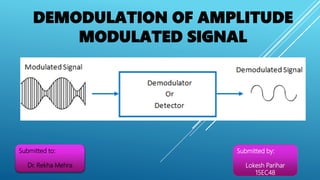
- 1. DEMODULATION OF AMPLITUDE MODULATED SIGNAL Submitted to: Dr. Rekha Mehra Submitted by: Lokesh Parihar 15EC48
- 2. WHAT IS AMPLITUDE MODULATION? It is a system of modulation in which the amplitude of the carrier signal is made proportional to the instantaneous amplitude of the modulating message signal.
- 3. WHAT IS DEMODULATION? Demodulation is the process of recovering original message signal from modulated wave. It also known as Detection. DETECTION OF AMPLITUDE MODULATED SIGNAL 1. Envelop Detector or Average Detector 2. Square Law Detector 3. Synchronous Detector or Coherent Detection
- 4. Envelop Detector An envelope detector is an electronic circuit that takes a high-frequency signal as input and provides an output which is the envelop of the original signal. The capacitor in the circuit stores up charge on the rising edge, and releases it slowly through the resistor when the signal falls. The diode in series rectifies the incoming signal, allowing current flow only when the positive input terminal is at a higher potential than the negative input terminal.
- 5. Capacitor discharge between positive peaks produces a ripple signal of frequency ωc in the output. By increasing the time constant RC, ripple can be reduced so that the capacitor discharges very little between the positive peaks. The envelop voltage is given by Ac [1+m cosωm t] Time rate of decrease of this voltage is - 𝒅𝒗 𝒅𝒕 = Ac mωm sinωm t Rate of Capacitor discharge = Ac [1+m cosωm t] 𝑹𝑪 In order to avoid carrier ripple the rate of capacitor discharge that should be greater than the rate of drop of voltage Ac [1+m cosωm t] 𝑹𝑪 ≥ Ac m ωm sinωm t 1 𝑹𝑪 ≥ mωm sinωm t 1+m cosωm t 1 𝑹𝑪 = mωm ≅ 0.3 or 0.4
- 6. SQUARE-LAW DEMODULATOR Square law demodulator is used to demodulate low level AM wave. Square Law Device Low Pass Filter AM wave Demodulated Output Ac 2 (1+m cosωm t) 2 cos 2 ωc t Ac 2 (1+m 2 cos 2 ωm t+ 2m cosωm t) cos 2 ωc t Ac 2 (cos 2 ωc t +m 2 cos 2 ωc t cos 2 ωm t+ 2m cos 2 ωc t cosωm t) We get by above equation:- 2ωc , ωc – ωm , ωc + ωm , ωc – 2ωm and ωm We will use a Low Pass Filter with frequency ‘fm’ to extract only ωm. As shown in above figure.
- 7. Amplitude Modulation 1. The equation for AM wave is s(t)= Ac [1+µ cosωm t] cosωc t 2. The value of modulation index is always between zero and one. 3. Transmitted power is dependent upon modulation index PT = Pc [ 1+ µ2 2 ] 4. In an AM signal, only two sidebands are produced, for any value of modulation index. 5. The amplitude of the sidebands is dependent on the modulation index, and is always less than the amplitude of carrier. Frequency Modulation 1. The equation for FM wave is s(t)= Ac cos[ωc t+β sinωm t] 2. The modulation index can have value either less than one or more than one. 3. Since in FM, amplitude of carrier is constant, the transmitted power is constant, independent of the modulation index. 4. The modulation index determines the number of significant pairs of sidebands in an FM signal. 5. The amplitude of the carrier and sidebands vary with the modulation index and can be calculated with Bessel functions. Difference Between Amplitude Modulation and Frequency Modulation
- 8. Amplitude Modulation 6. The sideband amplitude is never zero for any value of modulation greater than zero. 7. The bandwidth of an AM signal is twice the highest modulating frequency. 8. For AM, % of modulation is the ratio of amplitude of modulating voltage to the amplitude of the carrier multiplied by 100. 9. The AM system is more susceptible to noise and more affected by noise than FM. 10. When two AM signals occupy the same frequency, both signals will generally be heard regardless of relative signal strength. 11. The efficiency of AM is less than that of FM due to use of class-B amplifier. 12. The bandwidth required to transmit AM signal is much less than that of FM typically 10KHz in AM broadcasting. Frequency Modulation 6. The carrier of sideband amplitudes are zero at some modulation index. 7. The bandwidth of an FM signal is proportional to the modulation index. 8. For FM, the % of modulation is the ratio of the actual frequency deviation and the maximum permissible frequency deviation multiplied by 100. 9. The main advantage of FM over AM is its noise immunity, as limiter stage in FM receiver clips off noise signals. 10. The capture effect in FM allows the strongest signal on a frequency to dominate without interference from the other signal 11. In FM, greater transmitter efficiency can be realized using class-C amplifiers, as amplitude of FM signal is constant. 12. The bandwidth of FM signal is much more than the bandwidth of AM. The bandwidth of a typical FM channel is 200KHz.
- 9. Sources: • Internet • Electronic Communication Systems (4th Edition) • Lecture Notes