
Recommended
More Related Content
What's hot
What's hot (20)
Similar to Torsion Formula & Stress Strain
Similar to Torsion Formula & Stress Strain (20)
More from Lisa Benson
More from Lisa Benson (20)
Recently uploaded
Recently uploaded (20)
Torsion Formula & Stress Strain
- 1. TORSION
- 2. Learning Objectives: • Describe the torsion formula (shear stress in torsion) • Calculate stresses in a body under torsional loading • Graph and explain results of a torsion test
- 3. What are stresses and strains in structures subjected to twisting couples (torsion)? • Torsion twists a structure about an axis (neutral axis) • Unlike normal stress in axial loading, shear stresses in torsion are not uniformly distributed • Shear stresses proportional to distance from neutral axis
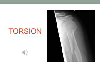
- 4. Tensile and compressive stresses in torsion on surface • Maximum tensile and compressive stresses occur on surfaces Spiral fracture of the tibia From http://radiopaedia.org/cases/tibial- spiral-fracture • Spiral fractures initiate in shear, followed by cracking along lines of maximum tensile stress.
- 5. Torsion Formula • In elastic range, torsion formula describes shear stresses in transverse plane • Shear stress varies with radius (distance from neutral axis): Tr / J J = polar moment of inertia (geometric property) Max shear stress at outer radius ro : max Tro / J
- 6. Torque is dependent on position along length (L) • Angular deformation = shear angle From Ozkaya and Nordin, Fundamentals of Biomechanics
- 7. Principal Stresses in Torsion • Principal normal stresses occur 45 degrees with the centerline: p = 45º • Max and min (principal normal stresses) are equal in magnitude, opposite in direction (tensile and compressive) • Magnitude of principal normal stresses = shear stress along longitudinal planes 1, 2 = +/-max From Ozkaya and Nordin, Fundamentals of Biomechanics
Editor's Notes
- Torsional loading is a geometric variation of shear and acts to twist a structure about an axis (the neutral axis). Maximum tensile and compressive stresses occur on the surface and distant from the neutral axis; these stresses are proportional to the distance from the neutral axis. Shear stress distribution about the neutral axis of a circular shaft in torsion. Shear stress increases as a function of distance from the neutral axis
- Maximum tensile and compressive stresses are generated normal to each other and on a diagonal to the neutral axis. If you imagine a line of length L drawn down the length of the shaft, as the shaft is twisted, the line lengthens. That increase in length indicates tensile stresses, as shown in this diagram. Conversely, compressive stresses result from the shortening of a line in the direction opposite to the twist. Spiral fractures of bone are produced by torsional forces applied to the structure; but failure of the material typically occurs in tension along the line of maximum generated tensile stress. Spiral fracture pattern begins with crack initiation in a shear mode parallel to the neutral axis, followed by crack propagation along the line of maximum tensile stress. Torsional (spiral) fractures usually initiated at smallest cross-sections: upper and lower 1/3 of humerus, femur, and fibula; upper 1/3 of radius; lower ¼ of ulna and tibia; and mid-clavicle
- A material under torsional loading experiences maximum shear stresses on planes perpendicular and parallel to the neutral axis
- The amount of deformation is measured in terms of shear angle (theta). Angle of twist ϒ= deformation of the shaft, or circumferential motion of particles along line L during deformation Elongation of line with length L to L’ during twist indicates tensile stresses; shaft deforms not only in shear but also subject to normal stresses
- Under pure torsion, principal normal stresses occur on planes whose normal are at 45 degrees with the centerline. [Think of the brittle failure of a piece of chalk when twisted; it fails along lines of tensile stress.] They are equal in magnitude, opposite in direction (tensile and compressive); magnitude = shear stress τzθ