
Recommended
More Related Content
Similar to Here are the steps to solve this problem:1. Draw the free body diagram of the beam and label the loads and supports.2. Determine the reactions at the supports by summing moments and forces. 3. Draw the load diagram above the FBD. 4. Determine the shear at each section from the loads and reactions to the left using ΣFy=0. Draw the shear diagram below the load diagram. 5. Determine the moment at each section from the shear values to the left using ΣM=0. Draw the moment diagram below the shear diagram.6. Note the maximum positive and negative values of shear and moment on their respective diagrams.7. Label
Similar to Here are the steps to solve this problem:1. Draw the free body diagram of the beam and label the loads and supports.2. Determine the reactions at the supports by summing moments and forces. 3. Draw the load diagram above the FBD. 4. Determine the shear at each section from the loads and reactions to the left using ΣFy=0. Draw the shear diagram below the load diagram. 5. Determine the moment at each section from the shear values to the left using ΣM=0. Draw the moment diagram below the shear diagram.6. Note the maximum positive and negative values of shear and moment on their respective diagrams.7. Label (20)
Recently uploaded
Recently uploaded (20)
Here are the steps to solve this problem:1. Draw the free body diagram of the beam and label the loads and supports.2. Determine the reactions at the supports by summing moments and forces. 3. Draw the load diagram above the FBD. 4. Determine the shear at each section from the loads and reactions to the left using ΣFy=0. Draw the shear diagram below the load diagram. 5. Determine the moment at each section from the shear values to the left using ΣM=0. Draw the moment diagram below the shear diagram.6. Note the maximum positive and negative values of shear and moment on their respective diagrams.7. Label
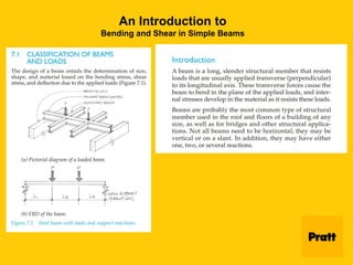
- 1. An Introduction to Bending and Shear in Simple Beams
- 2. An Introduction to Bending and Shear in Simple Beams
- 3. An Introduction to Bending and Shear in Simple Beams
- 4. An Introduction to Bending and Shear in Simple Beams
- 5. An Introduction to Bending and Shear in Simple Beams Roller Support
- 6. An Introduction to Bending and Shear in Simple Beams Pinned Support
- 7. An Introduction to Bending and Shear in Simple Beams Fixed Support
- 8. An Introduction to Bending and Shear in Simple Beams Types of Loads on a Beam Concentrat ed Uniformly Distribute d
- 9. An Introduction to Bending and Shear in Simple Beams Types of Loads on a Beam Nonuniform ly Distributed Load Pure Moment
- 10. Understanding Bending and Shear in Simple Beams Internal Forces
- 11. Understanding Bending and Shear in Simple Beams Recap: Internal Forces
- 12. Understanding Bending and Shear in Simple Beams If the beam is sagging, the top of the beam will get shorter and so the normal forces in the top of the beam will be compressive. The bottom of the beam will get longer, and so the normal forces in the bottom of the beam will be tensile. Each of the normal tensile forces has a corresponding compressive force which is equal in magnitude but opposite in direction. As such these forces don’t produce a net normal force, but they do produce a moment.
- 13. Understanding Bending and Shear in Simple Beams As such these forces don’t produce a net normal force, but they do produce a moment. This means that we can conveniently represent the internal forces acting on the beam cross section using just two resultants, one shear force, which is a resultant of the vertical internal forces and one bending moment, which is a resultant of the normal internal forces. This is a very common way of representing internal forces within a beam. moment
- 14. Understanding Bending and Shear in Simple Beams Drawing the shear force and bending moment diagrams is just figuring out what these internal forces are at each location of the beam. These resultant shear forces and bending moments will depend on the loads acting on the beam and the way in which the beam is supported. Beams can be loaded in a number of ways (as previously discussed), the most common being concentrated forces, distributed forces, and concentrated moments.
- 15. Understanding Bending and Shear in Simple Beams Beams can also be supported in a number of different ways. They can have pinned supports, roller supports, or fixed supports – which restrain the beam in different ways. Pins prevent vertical and horizontal displacement but allow rotation. Roller supports prevent vertical displacement but allow horizontal displacement and rotation. Fixed supports prevent all displacements and rotations. If a certain degree of freedom is restrained at a support, we will have a corresponding reaction force or reaction moment at that location. For example, rotations are permitted for a pinned support so there is no reaction moment but displacements in the horizontal and vertical direction are prevented so we will have horizontal and vertical reaction forces.
- 16. Bending and Shear in Simple Beams Summarized • A beam is a long, slender structural member that resists loads usually applied transverse (perpendicular) to its longitudinal axis. • These transverse forces cause the beam to bend in the plane of the applied loads. • Internal stresses are developed in the material as it resists these loads. • The design of a beam entails the determination of size, shape, and material based on the bending stress, shear stress, and deflection due to the applied loads. • Not all beams need to be horizontal; they may be vertical or inclined. • Beams may have either one, two, or multiple reactions. Overhang roof joist supported by a glu-lam beam
- 17. Beam Classification Based on Supports - Summary Beam-Column Framework in Steel
- 18. 7.2 Shear and Bending Moment • Beams subjected to a variety of loading conditions, either singly or in any combination, must resist the loads and remain in equilibrium. • For the beam to remain in equilibrium, an internal force system must exist within the beam to resist the applied forces and moments. • Stresses and deflections in beams are functions of the internal reactions, forces, and moments. • Shear force in a beam is the internal force produced on a beam cross section, equal and opposite to the external force(s) present on that section of beam. • Bending moment is the internal couple acting on a beam's cross section equal and opposite to the external moment acting on the beam section. • For this reason, it is convenient to “map” these internal forces and to construct diagrams that give a complete picture of the magnitudes and directions of the forces and moments that act throughout the beam length.
- 19. Load, Shear and Moment Diagrams • The beam diagrams are referred to as load, shear (V), and moment (M) diagrams. • The load diagram is essentially the free-body diagram of the beam. • Shear diagrams show the transverse shears along beam's length. • A shear diagram is a graph in which the abscissa (horizontal reference axis) represents distances along the beam length, and the ordinates (vertical measurements from the abscissa) represent the transverse shear at the corresponding beam sections. • Moment diagrams are graphs of the bending moment along the beam's length. • A moment diagram is a graph in which the abscissa represents distances along the beam, and ordinates represent the bending moment at the corresponding sections.
- 20. Understanding Bending and Shear in Simple Beams The internal forces acting on the beam cross section using just two resultants, one shear force, which is a resultant of the vertical internal forces and one bending moment, which is a resultant of the normal internal forces. This is a very common way of representing internal forces within a beam. moment
- 21. An Introduction to Bending and Shear in Simple Beams
- 22. Load, Shear and Moment Diagrams - Sign Convention • A sign convention is necessary for shear and moment diagrams if the results obtained from their use are to be interpreted conveniently and reliably. • The shear at a section is considered positive when the portion of the beam to the left of the section cut tends to be in the up position with respect to the portion to the right of the section cut.
- 23. Sign Convention - (cont’d) • The bending moment in a horizontal beam is positive at sections for which the top fibers of the beam are in compression and the bottom fibers are in tension. • A positive moment generates a curvature that tends to hold water (concave-upward curvature), whereas a negative moment causes curvature that sheds water (concave-downward curvature). • The overhang beam exhibits a changing curvature that results in negative to positive to negative moments. • The implication here is that there is a transverse section(s) in the beam span where the bending moment is zero to accommodate the required sign change. • Such a section, termed the inflection point(s) or point of inflection, is almost always present in overhang and multiple- span beams.
- 24. 7.3 Equilibrium Method for Constructing Shear and Moment Diagrams • In the equilibrium method specific values of V and M are determined from statics equations that are valid for appropriate sections of the member. • A convenient arrangement for constructing shear and moment diagrams is to draw a free-body diagram (FBD) of the entire beam and construct shear (V) and moment (M) diagrams directly below. • An origin should be selected and positive directions should be indicated for the coordinate axes. • Since V and M vary as a function of x along the beam length, equations for V and M can be obtained from free-body diagrams of portions of the beam. • Complete shear and moment diagrams should indicate values of shear and moment at each section where they are maximum positive and maximum negative. • Sections where the shear and/or moment are zero should also be located.
- 25. Example Problem 7.1 - Equilibrium Method for V and M
- 26. Example Problem 7.1 - (cont’d)
- 27. Basic Curves and Their Properties
- 28. Load, Shear and Moment Diagrams - Semi-Graphical Method • General considerations for constructing V and M diagrams. • 1. When all loads and reactions are known, the shear and moment at the ends of the beam can be determined by inspection. • 2. At a simply supported or pinned end, the shear must equal the end reaction, and the moment must be zero. • 3. Both shear and moment are zero at a free end of a beam (cantilever beam or overhang beam). • 4. At a built-in or fixed-end beam, the reactions are equal to the shear and moment values. • 5. Load, shear, and moment diagrams are usually drawn in a definite sequence with the load diagram on top, followed by the shear diagram directly beneath it, and the moment diagram below the shear diagram. • 6. When positive directions are chosen as upward and to the right, a uniformly distributed load acting down will give a negative slope in the shear diagram, and a positive distributed load (one acting upward) will result in a positive slope.
- 29. Semi-Graphical Method - (cont’d) • 7. A concentrated force produces an abrupt change in shear. • 8. The change in shear between any two sections is given by the area under the load diagram between the same two sections: • 9. The change of shear at a concentrated force is equal to the concentrated force. • 10. The slope at any point on the moment diagram is given by the shear at the corresponding point on the shear diagram; a positive shear represents a positive slope and a negative shear represents a negative slope. • 11. The rate of increase or decrease in the moment diagram slope is determined by the increasing or decreasing areas in the shear diagram. • 12. The change in moment between any two sections is given by the area under the shear diagram between corresponding sections:
- 30. Example Problem 7.3 • Construct the V and M diagrams for the girder that supports three concentrated loads. • Draw the FBD of the girder and solve for the support reaction at each end. • Construction lines should be drawn beneath the FBD at locations where loads occur.
- 31. Example Problem 7.3 - (cont’d) • In plotting the shear diagram, follow the direction for each force (including the support reactions) and maintain a constant shear until another concentrated load is encountered. • The constant shear is a result of having no load areas that can cause a change in shear. • Beginning at the left support, the reaction pushes the shear to a magnitude of +11k. • No loads occur between A and B so the shear remains constant until the concentrated load at B pushes the shear down by 5k to - 6k. • Between B and C, the shear is constant until changed by the concentrated load of -10k. • The resulting shear goes from +6k to -4k, reflecting a change in shear equal to 10k (the concentrated load). • The shear remains constant at -4k between C and D until the -8k concentrated load pushes the shear down to -12k. • No load area exists between D and E, so the shear remains constant until the support reaction at E brings the shear diagram back to zero (a check on the condition of equilibrium).
- 32. Example Problem 7.3 - (cont’d) • Since the supports for the girder are a hinge and roller, the moment at the ends will be zero. • Again, beginning from the left support, the moment changes from zero at A to the area contained under the shear diagram between A and B. • The area is equal to: A=(11k)x(4')=44k-ft. • The shear area is a zero degree-curve, with a positive area. • This results in a 1st degree-curve, with a positive slope in the moment diagram. • Between B and C, the moment changes by the area A=(6k)x(6')=36k-ft., with a 1st degree-curve, positive slope. • The area under the shear diagram between C and D is equal to 20k-ft., generating a 1st degree-curve with a negative slope (the shear area is negative). • The last segment of shear area is 60k-ft., producing a negative slope (1°) which brings the moment diagram back to zero (which it needs to be for a roller support).