
Recommended
More Related Content
What's hot
What's hot (20)
Similar to Chap 4 telemetry
Similar to Chap 4 telemetry (20)
More from LenchoDuguma
Recently uploaded
Recently uploaded (20)
Chap 4 telemetry
- 1. 1 SET BY LENCHOTOO, 2011(2018-19) CHAPTER IV TELEMETERY APPLICATIONS 4.1 What is Telemetry? The term telemetry is derived from the two Greek terms: “tele” and “metron”, which mean “remote” or “far off” and “measure”, respectively. Accordingly, telemetry is the measurement of remote (or far-off) physical variables or quantities. A physical variable or quantity under measurement is called measurand. Telemetry is the science of gathering information at some remote location and transmitting the data to a convenient location to be examined and recorded. Telemetry can be done by different methods: optical, mechanical, hydraulic, Electric, etc. The mechanical methods, either pneumatic or hydraulic have acceptable results for short distances and are used in environments that have a high level of electromagnetic interference and in those situations where, for security reasons, it is not possible to use electrical signals, for example, in explosive environments. More recently, use of optical fiber systems allows the measurement of broad bandwidth and high immunity to noise and interference. Other proposed telemetry systems are based on ultrasound, capacitive or magnetic coupling, and infrared radiation, although these methods are not routinely used. The discussion in this chapter will be limited to the most-used systems: telemetry based on electric signals. The main advantage of electric over mechanical methods is that: Electrically based telemetry does not have practical limits regarding the distance between the measurement and the analysis areas, and can be easily adapted and upgraded in already existing infrastructures. Electric telemetry methods are further divided depending on the transmission channel that they use as wire telemetry and wireless (or radio) telemetry. Wire telemetry is technologically the simplest solution. The limitations of wire telemetry are the low bandwidth and low transmission speed that it can support. However, it is used when the transmission wires can use the already existing infrastructure, as, for example, in most electric power lines that are also used as wire telemetry carriers.
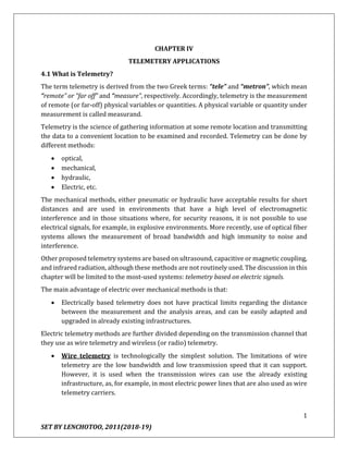
- 2. 2 SET BY LENCHOTOO, 2011(2018-19) Wireless telemetry is more complex than wire telemetry, as it requires a final radio frequency (RF) stage. Despite its complexity, it is widely used because it can transmit information over longer distances; thus, it is used in those applications in which the measurement area is not normally accessible. It can also transmit at higher speeds and have enough capacity to transmit several channels of information if necessary. Telemetry using radio waves or wireless offers several distinct advantages over other transmission methods. Some of these advantages are: No transmission lines to be cut or broken. Faster response time Lower cost compared to leased lines Ease of use in remote areas where it’s not practical or possible to use wire or coaxial cables Easy relocation Functional over a wide range of operating conditions Figure 4.1: Block diagram for a telemetry system. Telemetry using wires can be performed in either base-band or by sending a modulated signal, while wireless telemetry uses an RF carrier and an antenna. It consists of (not all the blocks will be always present) 1. transducers to convert physical variables to be measured into electric signals that can be easily processed; 2. conditioning circuits to amplify the low-level signal from the transducer, limit its bandwidth, and adapt impedance levels;
- 3. 3 SET BY LENCHOTOO, 2011(2018-19) 3. signal-processing circuit that sometimes can be integrated in the previous circuits; 4. subcarrier oscillator whose signal will be modulated by the output of the different transducers once processed and adapted; 5. codifier circuit, which can be a digital encoder, an analog modulator, or a digital modulator, that adapts the signal to the characteristics of the transmission channel, which is a wire or an antenna; 6. radio transmitter, in wireless telemetry, modulated by the composite signal; 7. impedance line adapter, in case of wire transmission, to adapt the characteristic impedance of the line to the output impedance of the circuits connected to the adapter; and 8. a transmitting antenna, for wireless communication, The receiver end consists of similar modules. For wireless telemetry, these modules are: 1. a receiving antenna designed for maximum efficiency in the RF band used; 2. a radio receiver with a demodulation scheme compatible with the modulation scheme; and 3. Demodulation circuits for each of the transmitted channels. For wireless telemetry, the antenna and the radio receiver are replaced by a generic front end to amplify the signal and adapt the line impedance to the input impedance of the circuits that follow. The transmission in telemetry systems, in particular wireless ones, is done by sending a signal whose analog variations in amplitude or frequency are a known function of the variations of the signals from the transducers. More recently, digital telemetry systems send data digitally as a finite set of symbols, each one representing one of the possible finite values of the composite signals at the time that it was sampled. The effective communication distance in a wireless system is limited by: The power radiated by the transmitting antenna, The sensitivity for the receiver and The bandwidth of the RF signal. As the bandwidth increases, the contribution of noise to the total signal also increases, and consequently more transmitted power is needed to maintain the same signal-to-noise ratio (SNR). This is one of the principal limitations of wireless telemetry systems. In some applications, the transmission to the receiver is done on base band, after the conditioning circuits. The advantage of base-band telemetry systems is their simplicity, although because of the base- band transmission, they are normally limited to only one channel at low speeds.
- 4. 4 SET BY LENCHOTOO, 2011(2018-19) 4.2 Telemetry Systems Overview Telemetry is defined as the sensing and measuring of information at some remote location and then transmitting that information to a central or host location. There, it can be monitored and used to control a process at the remote site. Various mediums of transmitting data from one site to another have been used. Data radio provides a wireless method for transmitting the information. Telemetry using radio waves or wireless offers several distinct advantages over other transmission. Or Telemetry is the process by which an object’s characteristics are measured (such as velocity of an aircraft), and the results transmitted to a distant station where they are displayed, recorded, and analyzed. The transmission media may be: Air and space for satellite applications, or Copper wire and fiber cable for static ground environments like power generating plants. In today's telemetry applications, which support large numbers of measurands, it is too costly and impractical to use separate transmission channels for each measured quantity. The telemetry process involves grouping measurements (such as pressure, speed, and temperature) into a format that can be transmitted as a single data stream. Once received, the data stream is separated into the original measurement’s components for analysis. Telemetry lets you stay in a safe (or convenient) location while monitoring what's taking place in an unsafe (or inconvenient) location. Aircraft development, for example, is a major application for telemetry systems. During initial flight testing, an aircraft performs a variety of test maneuvers. The critical flight data from a maneuver is transmitted to flight test engineers at a ground station where results are viewed in real time or analyzed within seconds of the maneuver. Real-time monitoring
- 5. 5 SET BY LENCHOTOO, 2011(2018-19) allows the "safety officer" to make instant decisions on whether to proceed with or terminate a test. With real-time analysis, the flight test engineer can request a maneuver be repeated, the next maneuver be performed, or test plan alternatives be substituted. Real-time data is also captured to storage media, such as disk and tape, for later analysis and archiving. A telemetry system is often viewed as two components, The Airborne System and The Ground System. In actuality, either or both may be in the air or on the ground. Data acquisition begins when sensors (transducers) measure the amount of a physical attribute and transform the measurement to an engineering unit value. Some sensors produce a voltage directly (thermocouples for temperature or piezoelectric strain gages for acceleration), while others require excitation (resistive strain gages, potentiometers for rotation, etc.). Sensors attached to signal conditioners provide power for the sensors to operate or modify signals for compatibility with the next stage of acquisition. Since maintaining a separate path for each source is cumbersome and costly, a multiplexer (known as a commutator) is employed. It serially measures each of the analog voltages and outputs a single stream of pulses, each with a voltage relative to the respective measured channel. The rigorous merging of data into a single stream is called Time Division Multiplexing or TDM. The scheme where the pulse height of the TDM stream is proportional to the measured value is called Pulse Amplitude Modulation (PAM). A unique set of synchronization pulses is added to identify the original measurands and their value. PAM has many limitations: Including accuracy,
- 6. 6 SET BY LENCHOTOO, 2011(2018-19) Constraints on the number of measurands supported, and The poor ability to integrate digital data. Pulse Code Modulation (PCM) is today’s preferred telemetry format for the same reasons that PAM is inadequate. Those: Accuracy is high, With resolution limited only by the analog to digital converter (ADC), and Thousands of measurands can be acquired along with digital data from multiple sources, including the contents of the computer’s memory and data buses. In a PCM-based system, the original PAM multiplexer’s analog output is digitalized to a parallel format. The Output Formatter along with synchronization data for measurand identification merges this, plus other sources of digital data. The Output Formatter serializes the composite parallel data stream to a binary string of pulses (1’s and 0’s) for transmission on copper wire, fiber cable, or "the ether." All components from after the sensor to the formatter comprise the encoder (see figure below}. Other, often remote encoders are used to multiplex additional sensor data into the main encoder’s output. Not only does this expand the number of measurands to thousands per stream, but it also eliminates the weight of cables required for each sensor. The output of the main encoder is filtered and transmitted via; Radio transmitter and antenna, coax cable, telephone line, Tape recorder, etc. Filtering rounds or smoothies the square data pulses to reduce frequency content and thus the required transmitter bandwidth. At the Ground Station, The received data stream is amplified. Since the transmission path often distorts the already rounded signal, a bit synchronizer reconstructs it to the original serial square wave train. Then, a decommutator recognizes the synchronization pattern and returns the serial digital stream to parallel data. Decom also separates the PCM stream into its original measurands (also known as prime parameters) and data. The computer or the telemetry front end selects prime parameters for real-time processing; archiving to disk or tape; display; output to strip chart recorders and annunciators; or distribution to other computing resources according to the test plan.
- 7. 7 SET BY LENCHOTOO, 2011(2018-19) 4.3 Airborne Systems Data Acquisition A wide variety of sensors (also known as transducers) are used to measure and acquire a physical property’s value. It is up to the instrumentation engineer to select the device to meet the environmental, response, accuracy, size, and cost specifications for the application. Signal conditioners serve as the interface of the data acquisition system from the transducers. Many transducers require: Ac or dc power (e.g., thermistors, strain gages, and linear variable differential transformers-LVDTs) Others generate signals (tachometers, thermocouples, and piezoelectric strain gages). They provide excitation power), network calibration, signal amplification, and filtering. In airborne data acquisition, sensor output characteristics must be Transformed, filtered, or Modified for compatibility with the next stage of the system. The absolute relationship between the output and the actual property value of the measurand may vary with time, altitude, pressure, temperature, etc. Therefore, signal conditioners also incorporate calibration features to assist in defining the relationships. A system under test may be subjected to known physical characteristics and the output measured to ascertain and verify the relationship between the sensor and its output. For example, when on the ground, an airplane’s flaps may be moved at known angles, while measurements are taken on sensor or airborne system output. The plot of angle vs. output will be used by the ground system for real-time data display in engineering units.
- 8. 8 SET BY LENCHOTOO, 2011(2018-19) Multiplexer Whatever the quantities monitored at the data source (whether electrical or physical), the cost to transmit each quantity through a separate channel would be prohibitive. Think of: The equipment and cables or Frequency spectrum required to monitor and Transmit several hundred or thousands of measurands! One way to conserve resources is to share time or frequency spectrum with techniques such as Time-Division Multiplexing (TDM) and Frequency Multiplexing (FM), respectively. If more than one physical variables need to be telemetered simultaneously from the same location, then one of the following multiplexing techniques is used: Time-division multiplexing (TDM), frequency-division multiplexing (FDM), and Wavelength-division multiplexing (WDM). Today, the most popular form of telemetry multiplexing (originally called commutation, as in an electric motor’s commutator) is TDM. Modulation Modulation is the process whereby some characteristic of one wave is varied in accordance with some characteristic of another wave. The basic types of modulation are: Angular modulation (including the special cases of phase and frequency modulation) and amplitude modulation. In missile radars, it is common practice to amplitude modulate the transmitted RF carrier wave of tracking and guidance transmitters by using a pulsed wave for modulating, and to frequency modulate the transmitted RF carrier wave of illuminator transmitters by using a sine wave. Or in other words Modulation is the technique where the value of each sample (i.e., the modulating signal) systematically changes the characteristics of a carrier signal (e.g., amplitude (height) or frequency (timing)). The resulting modulated wave "carries" the data. Conversely, removing the carrier signal results in the return of the original measurement. The TDM stream produced by the basic multiplexer scheme is accomplished via Pulse Code Modulation or PAM. Three other modulation forms are also used: Pulse Duration Modulation (PDM), Pulse Position Modulation (PPM), and Pulse Amplitude Modulation (PAM).
- 9. 9 SET BY LENCHOTOO, 2011(2018-19) The resulting waveforms from these modulation techniques for a simple analog data signal are shown below. The PAM data stream signal is transmitted from the multiplexer in a uniformly spaced sequence of constant-width pulses. The intensity of each pulse is modulated by amplitude. This is similar to AM radio broadcast, except the carrier is a pulse rather than a sine wave. Since amplitudes are degraded by noise, the multiplexed data stream is usually converted to a constant amplitude pulse modulation scheme. PDM carries the information in the pulse width, which varies directly to the amplitude of the signal. PPM results if the PDM waveform is differentiated, then rectified. The distance between the two pulses represents the sampled amplitude of the sine wave, with the first pulse as the zero time reference. Average system power for PPM is much lower than that required for PDM, but at the expense of greater bandwidth. Both PDM and PPM use constant-amplitude pulses, but are still analog representations of an analog signal. In a PCM system, each pulse is encoded into its binary equivalent before transmission. During PCM encoding, the serial output stream is conditioned for the communication link. In many cases, PCM data is not only transmitted, but also stored. When considering recording or transmitting requirements, you must establish the patterns used to represent logical one and zero values. Commutation a complete scan by the multiplexer (one revolution of the commutator) produces a frame of the stream of words containing the value of each measurand. Every scan produces the same sequence of words. Only the value of a measurand is captured, not its address (name). If only the measurand’s data is captured, there is no way to distinguish the owner of one value from the next. Thus, a unique word called the frame sync is added at the end of each frame to serve as a reference for the process of de-commutating the stream’s data (i.e., extracting it into individual measurand values).
- 10. 10 SET BY LENCHOTOO, 2011(2018-19) In a simple commutator, each data word is sampled once per revolution at a rate compatible with the measurand with the fastest changing data. Since the rate of change of a measurand's value varies tremendously, the sampling frequency rate must accommodate it. As an example, to characterize vibration requires many more samples per second (thousands) than temperature (fractions). According to the Nyquist Theorem, you must sample data at twice the maximum frequency component for the signal to be acquired. Sampling rates of 5 times the maximum frequency component are typical. A low pass filter is used to eliminate any frequencies that you cannot accurately digitize to prevent aliasing. If we were to take a worst-case approach to sampling all measurands at the highest rate, we could expect much waste in carrier frequency spectrum and power. Sampling rates should therefore vary with respect to frequency content and be somewhat independent of other measurands with different periodic acquisition rates. Highly sampled measurands are super- commutated with multiple occurrences of the measurand in each frame. Data Words A data word is a measurement, calculation, counter, command, tag, function, or other information entered into the frame position as a measurand. A measurand is a uniquely identified source (e.g., temperature of location 256, cabin pressure, fuel consumption obtained from an avionics bus, or a dump of the flight computer’s memory.) Each cell position in each frame contains the same measurand (sub-frames and embedded asynchronous frames) may appear to be an exception, but are not.
- 11. 11 SET BY LENCHOTOO, 2011(2018-19) Common Words Common words are filler words that do not contain a measurand and are filled with a common pattern. This pattern can be static, such as a hexadecimal word, or dynamic, such as the value of an input port or function generator. Common words are entered into all unused frame words. Encoders normally build a frame for transmission by first filling the entire frame with common words, then overwriting each word by the required data frame and subframe sync words, which are followed by measurands as the major frame is completed. Frame Synchronization Pattern Identifying the end of each minor frame period is the synchronization (sync) word, which is a unique sequence of 1's and 0's. The pattern is generally a pseudo-random sequence that is unlikely to occur randomly in the acquired data and usually occupies two words (or more) in the minor frame. The IRIG-106 Standard lists recommended patterns for lengths 16 through 33 bits. The first three bits transmitted in a frame sync pattern are always a "1," regardless of LSB or MSB alignment.
- 12. 12 SET BY LENCHOTOO, 2011(2018-19) The length of the frame sync is longer than usual data words to reduce the probability of actual data matching it. The frame sync should also be commensurate with the number of words in the minor frame (typically, it occupies 1 to 5 percent of the total minor frame). An identical pattern is repeated for every minor frame on the assumption that random data will not consistently match the defined pattern. The decommutator can then be programmed to lock onto this pattern to begin regenerating the original commutated measurands. 4.4 Ground System Setup and Control All the robust features of a ground system are for naught if you cannot easily set up and control it. This is where the term "user-friendly" takes on importance. Setting up a telemetry ground station includes: Creating the definition for the data acquisition system, including sensor characteristics and signal conditioners. Defining the telemetry frame(s) to accommodate sampling rate requirements as well as limitations of the acquisition hardware. The stream is defined down to the word and bit level if results will be displayed or data analyzed in real time. (Wizards are
- 13. 13 SET BY LENCHOTOO, 2011(2018-19) available to automatically create the frame definition based on constraints and requirements.) Defining data for appropriate words in the stream to drive the PCM simulator for system checkout and training. Entering calibration information for every sensor if data will be evaluated in engineering units, or using information from the airborne systems database Specifying, and where necessary, creating algorithms and their coefficients required for deriving parameters or engineering unit conversion. Creating displays for each display terminal, including objects, their size, attributes, and location, as well as measurands to be displayed. Defining data to be archived to disk. Allocating measurands and derived parameters destined for strip chart recorders and other output devices. The time required to set up and check out telemetry systems is significant. Since the setup files for both the airborne and ground system contain a large subset of common data it can be helpful to utilize file translation tools or a common database system. Use of the Telemetry Attributes Transfer Standard (TMATS) is an increasingly popular method to transfer files between non-compatible ground systems. Since each system uses a different internal format, translators are required to convert data to and from the TMATS intermediate format.
- 14. 14 SET BY LENCHOTOO, 2011(2018-19) Other, more elaborate alternatives utilize a relational database management system (RDBMS) such as Microsoft Access or Oracle to maintain setup files for airborne, flight line, and ground systems. Information regarding the calibrations, data streams, etc. requires entry only once. Not only can these systems produce the complete set of setup files from airborne sensors to ground station displays but they can maintain historical files to recreate any specific test scenario. Generally, these are one-of-a-kind projects tailored to specially configure airborne and ground systems and they adhere to the methodology of the ground center. PCM Stream Reconstruction At the ground station, the PCM stream, whether carried directly over wire or fiber, or ingested via an antenna and RF telemetry receiver, is reconstituted into the original raw measurands and data.
- 15. 15 SET BY LENCHOTOO, 2011(2018-19) Because transmission distorts data for both transmission mediums (wire versus "antenna"), the received PCM data signal must first be reconstructed. Prior to transmission, the square wave PCM stream is filtered to round the wave train, thus reducing the bandwidth required to carry it and ensuring power is concentrated in the spectrum carrying the data. The first signal processing function reconstructs the signal with a minimum number of symbol errors. Then the synchronous timing information is derived. This crucial signal processing function is called bit synchronization. A bit synchronizer or "bit sync" is a device that establishes a series of clock pulses that are synchronous to an incoming signal. The bit sync then classifies the value of each bit in the stream. Frame Synchronization The reconstructed PCM telemetry stream remains a serial wave train of 1’s and 0’s. Before converting this serial stream into words containing characters, numbers, nibbles, and individual bits, the reference point or synchronization word must first be isolated. This is the task of frame synchronization. Heritage ground telemetry systems required a frame synchronizer, a dedicated 5.25-inch by 19-inch rack-mount chassis, to isolate minor frames. The frame sync first located the frame synchronization pattern and then passed the frame of fixed length words to a word selector, sub-frame selector(s), or computer for de-commutation into individual words. The word selector passed a few chosen words to an annunciator or strip chart recorder for real-time quick-look PCM streams are not always received with continuous complete errorless frames. Isolating the frame sync task is complicated by the presence of bit errors, slippage (undetected bit(s)), and random data sequences. Users can choose the number of valid frames before accepting data as well as the level of confidence that valid data is received by specifying the frame
- 16. 16 SET BY LENCHOTOO, 2011(2018-19) sync's ability to detect valid frame sync patterns. With respect to numbers of valid frames, four states or operational modes are considered in the diagram and definitions below: Search The synchronizer looks for a possible sync pattern. Verify A pattern is tentatively identified, a window is set at the predicted time of reoccurrence of the sync pattern, and the masked sync pattern is checked for several frames. If the pattern recurs in the sync window for a prescribed preset number of frames, the synchronizer advances to lock. Lock The synchronizer continues to look for the frame sync pattern in the sync window and will only revert to a previous mode if the sync pattern fails to occur in the window for a given number of frames. Once frame synchronization is established, commutated and supercommutated measurands can be identified since the position of the data values is known relative to the frame sync pattern. Check After being in lock, an expected frame sync pattern is not detected. This state is the converse of the "verify" mode. The conditions required to move between operational modes is also defined:
- 17. 17 SET BY LENCHOTOO, 2011(2018-19) Lock to Search Number of consecutive invalid frame synchronization patterns that must be detected in the data stream before the decom goes into search mode. For example, if the constraint is set to 3, decom will go into search if it detects three consecutive invalid frame synchronization patterns in the data stream. When it detects the first invalid frame synchronization pattern, it advances from lock to verify mode. It remains in verify mode when it detects the second invalid frame synchronization pattern. If the third frame synchronization pattern is invalid, it advances to search; otherwise, it will return to lock. If the constraint is set to 1, decom will bypass the verify mode and go right into lock upon the identification of one frame sync pattern. Search to Lock Number of consecutive valid frame synchronization patterns that must be detected in the data stream before the decom advances from search to lock. For example, if you enter 3, decom will not advance from search to lock until it detects three consecutive valid frame synchronization patterns in the data stream. When it detects the first valid frame synchronization pattern, it advances from search to check mode. It remains in check mode when it detects the second valid frame synchronization pattern. If the third frame synchronization pattern is valid, it advances from check to lock. Otherwise, it will return to search. A 100% match of the actual to programmed pattern may not always be attainable. Thus, decoms have several programmable options to allow advancement to the next state. Sync Pattern Bit Errors Calculates the number of correct bits in the synchronization pattern for a valid pattern. For example, if the synchronization pattern is 32 bits long and the Sync Pattern Bit Errors is set to 4, then decom will look for 28 good bits in a pattern. Bit Aperture Allows or disallows bit slips in the frame synchronization pattern. Four example, 1 allows the frame synchronization pattern to be "early" or "late" by one bit time and still be valid for a lock state. Similar techniques can be used to detect subframe sync words. While sync words test the overall integrity of one location, a Cyclic Redundancy Check (CRC) word may be included in the frame to check the integrity of an entire frame (although this is not included in the IRIG-106 specification).
- 18. 18 SET BY LENCHOTOO, 2011(2018-19) De-commutation After frame synchronization, individual measurands are identified according to the frame location. Hardware architectures differ in how they equate and maintain the data/definition relationship. For example, a unique tag may be appended to each raw measurand or data word in what may be called a data flow architecture. This tag remains with the data word unless it is changed; i.e., EU converted, processed, or its bits manipulated. Another scheme rearranges measurands into a new format that is more appropriate for data manipulation, such as sorting the frame into arrays where each array is one or more instances of a single measurand. Another scheme maintains a current value table (CVT), including all or only those measurands of interest. The decommutator also identifies and extracts embedded asynchronous data stream (EADS) words. Words for each EADS are re-serialized and sent to separate hardware decommutators along with clocks, or if data rates permit, to a general-purpose embedded processor or workstation as contiguous bytes for software decommutation algorithms. All words in the same EADS stream have an identical tag or name. Thus, a major frame may have multiple EADS streams, each destined for an independent decommutator. Analogous to sub-subframes, an EADS stream may itself have EADS stream(s). Other features often found in hardware decommutators include the ability to support; Words of different lengths, multiple CRC and parity checking types, and Selectable data alignment (MSB/LSB) on a per word basis. Applications such as monitoring multiple stage rockets or testing multiple systems on one aircraft require changing the set of measurands being monitored. That means the contents of the entire frame will change significantly, if not completely. You could use a single large frame covering all measurands. However, the spectrum required to transmit this larger number of words is too large. Instead, formats are changed as each stage is jettisoned or test points fluctuate. The change occurs on the value of a specific measurand. A multi-format decom will switch to a new format either on the next word or next frame without loss of data. To achieve such a rapid response, the decommutator contains all the possible frame definitions in memory. The IRIG-106 Standard specifies a maximum of 16 formats. Only a few formats are typically used in aircraft flight test and rocket launches. Still, over a hundred formats may be used by a few satellites to accommodate relatively low data rates and multiple modes of operation. Fortunately, data rates are slow and could be accommodated by software decommutation.
- 19. 19 SET BY LENCHOTOO, 2011(2018-19) The advent of faster general-purpose front-end processors and computers offers a way to provide real-time software decommutation, but at slower data rates than a dedicated hardware decom. Software decommutation offers the advantage of handling the most complex formats and memory required to support instant switching between hundreds of frame formats. Today’s ground station management software includes a graphical user interface (GUI) to define telemetry stream decommutation content as in the database. Instant feedback occurs when data entry errors are detected (e.g., audible and visual feedback if the words entered for a minor frame contain more bits than what is defined for the frame). To aid in data entry, tools automatically create dummy measurand names, or for a supercommutated frame, create multiple instances of measurands automatically based on frequency, etc. Flight test programs often deploy multiple airborne and ground systems. Each system has unique data structures to define commutation and decommutation frame layout plus the governing attributes of the data acquisition devices or the ground displays. Each system may use independent databases. And each requires that redundant data be entered in a unique format. Personnel at large ground stations generally develop their own capability to convert one database format to another. The alternative is manual reentry and testing of each database. Limiting a test program to a single hardware suite is not always possible, which can be quite cumbersome as programs may last many years, precluding use of newer technology. Similar hurdles exist if unique test resources are only available at distant test facilities, each with different equipment (e.g., major differences in operating climates, threat simulators, munition test areas, etc). To eliminate the tedious task of database re-entry, ground station manufacturers have developed their own set of translators to support their equipment. A few have built this capability around a general-purpose relational database (RDBMS) such as Oracle or Microsoft Access. Recently, IRIG-106 included the definition of the Telemetry Attributes Transfer Standard (TMATS), an intermediate common format that each ground and airborne system can use for data transfer. Today, a superset of the TMATS specification is required to encompass all the attributes of the airborne and ground systems. Simulation and Encoding A data acquisition system or analog instrumentation recorder may not always be available at the telemetry station to produce PCM data streams for system checkout and operator training. Therefore, it is highly desirable to simulate identical PCM data streams produced by the acquisition subsystem. Simulators vary in performance; some produce a simple static frame at fixed rates, while others create the most complex frames and data rates to match the decommutator’s
- 20. 20 SET BY LENCHOTOO, 2011(2018-19) capabilities. Describing the frame format for setup may not be required since the telemetry system can produce it from the decommutator’s setup definition. The simulator produces major and minor frames, including super-commutated, sub-, and sub-sub frames; and multiple embedded asynchronous data streams. The PCM output signal is available in any of the standard IRIG codes and levels. Simulators and encoders also provide MSB or LSB word orientation, programmable synchronization words, and support for format switching. Measurands can be simulated statically either as user defined constants and wave shapes via a CVT or as multiple function generators (square, sine, ramp, triangular) at different data rates and amplitudes. While the data changes, it is not considered dynamic. Dynamic simulation uses real-time data from external sources and measurand simulators as products of data bus, vehicle, or satellite constellation models. These dynamically simulated streams are desirable for training and system test. A dynamic simulator is, in effect, a PCM encoder. You can produce a new PCM stream by extracting words from incoming PCM stream(s) or external data sources for applications such as commanding or forwarding data to another site. An example of the former is to control the operation of a satellite, while the latter is for an airborne-based ground station to forward key measurands to the ground station during flight tests (see figure below). The airborne ground station not only selects all instances of individual parameters, but may compress them (e.g., averages values or combines multiple measurands, as in processed parameters).
- 21. 21 SET BY LENCHOTOO, 2011(2018-19) Real-Time Processing The result of decommutation is the reconstruction of sensor measurements, packed bus data, or computer words. To be more meaningful and easily comprehended, measurements are viewed in user-friendly formats like engineering units (miles per hour, degrees centigrade, or psi), not as raw counts from a transducer. Real-time processing requires that data be converted/manipulated in real time to satisfy the immediate need to evaluate data and make decisions regarding safety, test continuation, controlling a satellite’s movement, etc. To L-3 Telemetry-West, real-time processing means producing all the results from an algorithm before the next set of measurands arrive. The alternative is non-determinism and loss of data until processing resources are available. While buffering data for a very short period may be acceptable, loss of data is not. Adding more or faster resources may not produce desired results. In cases like this, you need a high- performance deterministic system that supports linear processing growth, where doubling the number of processors doubles processing resources. In addition to EU conversion, real-time processors serve other functions, including the following: Alarm Checking-Real-time processors continuously check values against norms to ensure out-o f limits and caution boundaries are not exceeded or to predict problems due to trending over time. Bit Manipulation-Telemetry frames are not always orderly with one measurand per word. When resources are at a premium, instrumentation engineers will combine unused bits from several word locations to form an additional measurand. It is up to the real-time processor to assemble the new measurand and inject the result into the stream for further processing. Derived Parameters - A single meaningful attribute (e.g., air speed as a much number) may be the result or derivation of multiple measurands (temperature, altitude, velocity) inhabiting multiple data streams. Data Compression - Often, data is sampled too frequently, producing too much data. This data is "compressed" using sampling or averaging algorithms.