SlideShare a Scribd company logo
1 of 96
Download to read offline
• Top level of driving performance in compact body
• Easy operability
• Extensive option lineup
• Ensured maintenance
• Compact and space-saving
• Supporting various applications
INVERTER
FR-E700
All-rounder with a compact body
FACTORY AUTOMATION
2
Global Player
GLOBAL IMPACT OF
MITSUBISHI ELECTRIC
We bring together the best minds to
create the best technologies. At
Mitsubishi Electric, we understand
that technology is the driving force of
change in our lives. By bringing
greater comfort to daily life, maximiz-
ing the efficiency of businesses and
keeping things running across
society, we integrate technology and
innovation to bring changes for the
better.
Mitsubishi Electric is involved in many areas including the following
Energy and Electric Systems
A wide range of power and electrical products from generators to large-scale displays.
Electronic Devices
A wide portfolio of cutting-edge semiconductor devices for systems and products.
Home Appliance
Dependable consumer products like air conditioners and home entertain-
ment systems.
Information and Communication Systems
Commercial and consumer-centric equipment, products and systems.
Industrial Automation Systems
Maximizing productivity and efficiency with cutting-edge automation technology.
Through Mitsubishi Electric’s vision, “Changes for the Better“ are possible for a brighter future.
4
9
10
14
21
28
32
40
63
64
79
84
88
89
3
Features
Connection example
Standard Specifications
Outline Dimension Drawings
Terminal Connection Diagram, Terminal Specification Explanation
Operation panel, Parameter unit, FR Configurator
Parameter List
Explanations of Parameters
Protective Functions
Option and Peripheral Devices
Precautions for Operation/Selection, Precautions for Peripheral Device Selection
Application to Motor
Main Differences and Compatibilities with the FR-E500 Series
Warranty, Inquiry
Contents
The inverter became more powerful.
1 Top level of driving performance in compact body
(1) High torque 200%/0.5Hz is realized by Advanced magnetic flux vector control (3.7K or less)
By the advancement of General-purpose magnetic flux vector
control to Advanced magnetic flux vector control, top level of
driving performance became possible.
Since V/F control and General-purpose magnetic flux vector
control operations are available, operation after replacement of the
conventional model (FR-E500 series) is ensured.
For the 5.5K to 15K, 150%/0.5Hz torque is realized.
Evolution in all functionsEvolution in all functionsEvolution in all functionsEvolution in all functions
Many kinds of three phase induction motors can be optimally
controlled with Mitsubishi's original "non-rotation" auto tuning
function. High precision tuning is enabled even when a test
operation of a machine cannot be performed at parameter
adjustment.
Advanced auto tuning
Short time overload capacity is increased to 200% 3s (200% 0.5s for
the conventional model). Overcurrent trip is less likely to occur.
Improved torque limit/current limit function provides a machine
protection, load limit, and stop-on-contact operation.
(2) Short time overload capacity
is increased (200% 3s) (3) Torque limit/current limit function
Using the torque limit function, machine
breakage from overload can be avoided.
For example, edge chipping of a tool can be avoided.
When a bogie runs over a bump, the impact can
be beared by this function.
Speed/torque characteristics example
FR-E720-3.7K (SC) (NF) (NC) (Advanced magnetic flux vector control)
SF-JR 4P 3.7kW
-200%
-100%
0
100%
200%
500 1000
3Hz 30Hz 60Hz
Speed (r/min)
1500 2000
Load
torque (%)
Advanced magnetic flux vector control is ideal
for a lift in an automated-storage system which
requires high torque at low speed.
(4) Improved regeneration capability
A brake transistor is built-in to the 0.4K to 15K.
Connecting an optional brake resistor increases regeneration
capability.
4
Excellent usability
Usability was thoroughly pursued.
2
Setting dial is the feature of Mitsubishi inverters.
•Displayed numbers can be jumped by turning the setting dial quickly, and numbers can
be changed one by one by turning it slowly, enabling speedy parameter setting.
•The nonslip setting dial is easier to turn.
(1) Improved setting dial
Press and button
simultaneously (0.5s).
Turn to select
operation method.
Press to set.
According to the desired command sources for start frequency and speed, Pr.79 can be set in simple steps.
(2) Easy setting mode
Settingis
completed
An USB connector (mini-B connector) is provided as standard. The inverter can be easily connected without a USB-RS-485 converter.
Wizard (interactive) function of FR Configurator (inverter setup software) provides setting support.
In addition, a high-speed graph function with USB enables high speed sampling display.
(3) With a provided USB connector, setting is easily done from
a personal computer using FR Configurator
Inverter
FR Configurator
Acceleration/deceleration
pattern setting
Acceleration/deceleration
time setting
Parameter list display
Expanded advanced
operability with USB
and FR Configurator
High speed graph function
USB cable
Mini-B
connector
Setting wizard function (example: acceleration/deceleration time setting)
Optional enclosure surface operation panel (FR-PA07) can
be connected.
In addition, an operation panel for conventional model
(FR-E500 series) can be connected.
(5) Parameter unit FR-PU07/
FR-PU07BB(-L) (option)
The FR-PU07/FR-PU07BB(-L), an optional parameter unit, can
be connected as well.
A parameter unit connection cable (FR-CB20 ) is separately
required. (Parameter unit connection cable FR-CB203 (3m) is
enclosed with FR-PU07BB(-L).)
•Setting such as direct input method with a numeric keypad,
operation status indication, and help function are useful.
Thedisplaylanguagecanbeselectedfrom8languages.
•Parameter settings of maximum of three inverters can be stored.
•A battery pack type (FR-PU07BB(-L)) allows parameter setting
and parameter copy without powering on the inverter.
Easy/powerful compact inverterEasy/powerful compact inverterEasy/powerful compact inverterEasy/powerful compact inverter
Operation method Panel display
Start command Speedcommand Monitor LED
RUN button
External terminal
STF/STR
External terminal
STF/STR
Setting dial
RUN button
PU
Blinking
Blinking
BlinkingON
Blinking ON
EXT
PU EXT
PU EXT
PU EXT
1-97
2-97
3-97
4-97
Analog voltage
input
Setting dial
Analog voltage
input
BlinkingBlinking
and
flicker.
(4) Enclosure surface operation panel
FR-PA07 (option)
BlinkingBlinking
The operation panel of the inverter cannot be removed.
A parameter unit connection cable (FR-CB20 ) is
separately required.
To use a parameter unit with battery pack outside Japan, order the FR-PU07BB-L
(model indicated with "L" at the end).
•Features
•Standard
Specifications
•Outline
Dimension
Drawings
•Terminal Connection
Diagram
•Terminal Specification
Explanation
•Operation panel
•Parameter unit
•FR Configurator
•Parameter List
•Explanations
of Parameters
•Protective
Functions
•Option and
Peripheral Devices
•Precautions for
Operation/Selection
•Precautions for Peripheral
Device Selection
•Application
to Motor
•Warranty
•Main Differences and
Compatibilities with
the FR-E500 Series
•Service
•International FA Center
•Connection
example
5
Terminal
card
Enhanced expandability
Mitsubishi inverters offer the expandability that answers to every need
3
Compact and space saving
Compact design expands flexibility of enclosure design.
4
(1) A variety of plug-in options are mountable
Plug-in options supporting digital input, analog output extension, and a variety of communications provide extended functions which is
almost equivalent to the FR-A700 series. (One type of plug-in option can be mounted.)
(3) Control terminals are
selectable according to applications
(1) Compact body with
high performance function
Installation size is the same as
the conventional mode (FR-E500
series) in consideration of
intercompatibility. (7.5K or less)
(2) Side by side installation saves space
Space can be saved by side by side
no clearance installation*.
(4) Various kinds of networks are supported
•EIA-485 (RS-485), MODBUS®
RTU (equipped as standard),
CC-Link, PROFIBUS-DP, DeviceNet™
, LONWORKS®
(option)
•Network-compatible inverters, the CC-Link communication
model (FR-E700-NC) and the FL remote communication model
(FR-E700-NF), are also available.
(5) Environment-conscious filter options
•Filterpack FR-BFP2 (the package of the power factor improving DC
reactor, common mode choke, and capacitive filter) is available for
compliance with the Japanese harmonic suppression guidelines.
•A noise filter option for compliance with the EMC Directive
(EN61800-3 2nd Environment Category C3) is also available.
Plug-in option
Plug-in option dedicated front cover
Compatible Plug-in Options
•FR-A7AX (E kit) ... 16-bit digital input
•FR-A7AY (E kit) ... Digital output
Extension analog output
•FR-A7AR (E kit) ... Relay output
•FR-E7DS ............ 24VDC input*1
•FR-A7NC (E kit) ...CC-Link
•FR-A7ND (E kit) ...DeviceNet
•FR-A7NP (E kit) ...PROFIBUS-DP
•FR-A7NL (E kit) ...LONWORKS
FR-E720-0.2K FR-E520-0.2K
The FR-A7 E kit can be used for the standard control circuit terminal model only.
For the safety stop function model, use an FR-A7 and a separate dedicated front cover.
128mm
For the customers who need more than
the standard terminals, the control
terminal option, RS-485 2 port terminal
block, is available.
A terminal card is removable and can be
easily replaced from a standard terminal card.
*: Use the inverter at the surrounding air temperature
of 40˚C or less.
[For the standard control circuit terminal model, order the FR-A7 E kit, which contains an option board FR-A7 and its dedicated front cover.]
(2) Safety stop function (FR-E700-SC/NF/NC)
•Spring clamp terminals are adopted as control circuit terminals.
Spring clamp terminals are highly reliable and can be easily wired.
•The FR-E700-SC series is compliant to the EU Machinery Directive
without the addition of previously required external devices.
Operation of an external Emergency Stop device results in a highly
reliable immediate shutoff of the D700's output to the motor.
This safety stop function conforms to the following standards.
EN ISO 13849-1 Category 3 / PLd
EN62061 / IEC61508 SIL2
Provided by the user (present) FR-D700
Safety function
is equipped
Emergency stop Emergency stop
For conventional model...
Two MCs were necessary
For conventional model...
Two MCs were necessary
•High cost
•Maintenance of two MCs
was necessary
•Installation space was necessary
•Magnetic contactor (MC)
•Emergency stop wiring
Only one MC is recommended
instead of two.
Although MC is not required
for the safety stop function.
Only one MC is recommended
instead of two.
Although MC is not required
for the safety stop function.
•Cost reduction
•Maintenance of one MC
•Installation space is reduced
*: Approved safety relay unit
*
Mitsubishi magnetic
contactors
•Offer a selection of small frames
•Offer a line-up of safety contactors
•Support with low-level load (auxiliary contact)
•Support many international regulations as a standard model
Refer to page 77 for the selection.
*1: This option is available for the safety stop function model only. The dedicated front cover is enclosed with the option.
6
Ensured maintenance
700 series are the pioneer of long life and high reliability.
5
Full of useful functions6
•The design life of the cooling fan has been extended to 10
years*1
. The life of the fan can be further extended utilizing the
it’s ON/OFF control.
•The design life of the capacitors has been extended to 10 years*1
*2
by adopting a capacitor that endures about 5000 hours at 105°C
surrounding air temperature.
(1) Long-life design
A cooling fan is provided on top of the
inverter for all capacities requiring a
cooling fan*.
A cooling fan can be easily replaced
without disconnecting main circuit wires.
(3) Easy replacement of cooling fan
Since a wiring cover can be installed after
wiring, wiring work is easily done.
(4) Combed shaped wiring cover
Wiring of the control circuit when replacing the same series
inverter can be done by changing the terminal block.
(5) Removable control terminal block
•Degrees of deterioration of main circuit capacitor, control circuit
capacitor, and inrush current limit circuit can be monitored.
•Trouble can be avoided with the self-diagnostic alarm*4
that is
output when the life span is near.
*4: Any one of main circuit capacitor, control circuit capacitor, inrush current limit circuit or
cooling fan reaches the output level, an alarm is output.
Capacity of the main circuit capacitor can be measured by setting parameter at a stop and
turning the power from off to on. Measuring the capacity enables an alarm to be output.
*: The inverter may trip and the motor may coast depending on the load condition.
Detection of coasting speed (frequency search function) prevents the motor speed from
decreasing at a restart, starting the motor smoothly with less output current.
*1: Surrounding air temperature : annual average 40˚C (free from corrosive gas, flammable gas,
oil mist, dust and dirt) Since the design life is a calculated value, it is not a guaranteed value.
*2: Output current : 80% of the inverter rated current
*: Cooling fans are equipped with FR-E720-1.5K (SC) (NF)
(NC) or more, FR-E740-1.5K (SC) (NF) (NC) or more, and
FR-E720S-0.75K (SC) or more.
(2) Leading life check function
•Automatic restart after instantaneous power failure function with
frequency search
•Brake sequence mode is useful for mechanical brake control of a lift.
•Regeneration avoidance function prevents regenerative overvoltage in a pressing machine.
•Main circuit power supply DC input can be connected to DC power supply.
•Enhanced I/O terminal function supports switchover of analog input (voltage / current).
•Password function is effective for parameter setting protection.
and so on
•Power-failure deceleration stop function/operation continuation
at instantaneous power failure function
The motor can be decelerated to a stop when a power failure or
undervoltage occurs to prevent the motor from coasting.
This function is useful to stop a motor at power failure as a fail
safe of machine tool, etc.
With the new operation continuation function at instantaneous
power failure, the motor continues running without coasting
even if an instantaneous power failure occurs during operation.
•Estimated service lifespan of the long-life parts
Components
Cooling fan
Main circuit smoothing capacitor
Printed board smoothing capacitor
Estimated lifespan of the FR-E700
10 years
10 years
10 years
Guideline of JEMA*3
2 to 3 years
5 years
5 years
*3: Excerpts from “Periodic check of the transistorized inverter” of JEMA (Japan Electrical Manufacturer’s Association)
FR-E500 series FR-E700 series
Input voltage Output frequency
Motor speed
Output current
Input voltage Output frequency
Motor speed
Output current
Enhanced functions for all sorts of applications
Energy saving for fans and pumps
•Load pattern selection (Pr. 14)
Optimal output characteristics (V/F characteristics) for application or load characteristics can be selected.
•Optimum excitation control (Pr. 60)
With Optimum excitation control to achieve the highest motor efficiency, further energy saving can be achieved.
Refer to page 62
7
FeaturesOptionsInstructionsMotorCompatibilityWarrantyInquiry
Connection
example
Standard
Specifications
Operationpanel
Parameterunit
FRConfigurator
Parameter
List
Protective
Functions
Explanations
of
Parameters
TerminalConnection
Diagram
TerminalSpecification
Explanation
Outline
Dimension
Drawings
FR-E720 -0.1K
Lineup
:Available models :Not available
Inverter Model
Inverter Capacity 0.1K 0.2K 0.4K 0.75K 1.5K 2.2K 3.7K 5.5K 7.5K 11K 15K
Three-phase 200V FR-E720- (SC)
Three-phase 400V FR-E740- (SC)
Single-phase 200V FR-E720S- (SC)*
Single-phase 100V FR-E710W-*
*:Output of the single-phase 200V and single-phase 100V input specifications is three-phase 200V.
Inverter Model
Inverter Capacity 0.1K 0.2K 0.4K 0.75K 1.5K 2.2K 3.7K 5.5K 7.5K 11K 15K
Three-phase 200V FR-E720- NF/NC
Three-phase 400V FR-E740- NF/NC
Symbol
1
2
4
Voltage
100V class
200V class
400V class
Symbol
None
SC
NF
NC
Control circuit terminal
specification
Standard control circuit
terminal model (screw type)
Safety stop function model
FL remote communication model
CC-Link communication model
Symbol
0.1K
to
15K
Inverter Capacity
Represents the
inverter capacity
"kW".
Symbol
None
S
W
Number of Power Phases
Three-phase input
Single-phase input
Single-phase input
(double voltage output)
Complies with UL, cUL, and EC Directives (CE marking),
and the Radio Waves Act (South Korea) (KC marking).
It is also certified as compliant with the Eurasian Conformity (EAC).
The single-phase 100V power input model is not compliant with the EMC Directive.
The inverters are compliant with the EU RoHS Directive (Restriction of
the Use of Certain Hazardous Substances in Electrical and Electronic
Equipment), friendly to people and to the environment.
8
EMC filter (ferrite core)
(FR-BSF01, FR-BLF)
Motor
Earth
(Ground)
EMC filter (ferrite core)*1
(FR-BSF01, FR-BLF)
P/+
P/+
PR
PR
High power factor
converter (FR-HC2)
Power regeneration
common converter (FR-CV)
Resistor unit (FR-BR)
Discharging resistor (GZG, GRZG)
Earth
(Ground)
Install a noise filter to reduce the
electromagnetic noise generated
from the inverter.
Effective in the range from about
1MHz to 10MHz. A wire should be
wound four turns at a maximum.
AC power supply
Use within the permissible power supply
specifications of the inverter.
To ensure safety, use a moulded case circuit
breaker, earth leakage circuit breaker or
magnetic contactor to switch power ON/OFF.
Enclosure surface
operation panel (FR-PA07)
Connect a connection cable (FR-CB2) to
the PU connector to use the FR-PA07,
FR-PU07/FR-PU07BB(-L).*2
USB connector
A personal computer and an inverter can
be connected with a USB (Ver1.1) cable.
Molded case circuit breaker
(MCCB) or earth leakage current
breaker (ELB), fuse
The breaker must be selected carefully
since an in-rush current flows in the
inverter at power on.
Magnetic contactor (MC)
Install the magnetic contactor to ensure
safety. Do not use this magnetic contactor
to start and stop the inverter. Doing so will
cause the inverter life to be shorten.
Reactor (FR-HAL, FR-HEL
option)
Install reactors to suppress harmonics and
to improve the power factor.
A reactor (option) is required when
installing the inverter near a large power
supply system (500kVA or more).
The inverter may be damaged if you do
not use reactors. Select the reactor
according to the model. Remove the
jumpers across terminals P/+ - P1 to
connect the DC reactor.
Devices connected to the output
Do not install a power factor correction capacitor,
surge suppressor or radio noise filter on the output side
of the inverter. When installing a moulded case circuit
breaker on the output side of the inverter,
contact each manufacturer for selection of the
moulded case circuit breaker.
Earth (Ground)
To prevent an electric shock, always earth (ground) the
motor and inverter. For reduction of induction noise from
the power line of the inverter, it is recommended to wire
the earth (ground) cable by returning it to the earth
(ground) terminal of the inverter.
R/L1 S/L2 T/L3P1P/+
N/-P/+ U W
Brake unit (FR-BU2)
P/+
PR
V
Power supply harmonics
can be greatly suppressed.
Install this as required.*2
Great braking capability is obtained.
Install this as required.*2
The regenerative braking capability of
the inverter can be exhibited fully.
Install this as required.
Install a noise filter to reduce
the electromagnetic noise
generated from the inverter.
Effective in the range from
about 1MHz to 10MHz.
When more wires are passed
through, a more effective
result can be obtained. A
wire should be wound four
turns or more.
EMC filter
(capacitor)*1
(FR-BIF)
Reduces
the radio
noise.
Connection example
*1: Filterpack (FR-BFP2), which contains DC reactor and noise filter in one package, is also available.
*2: The converter is used for the standard control circuit terminal model or the safety stop function model.
DC reactor (FR-HEL)*1
AC reactor (FR-HAL)
Brake resistor
(FR-ABR, MRS, MYS)
Braking capability can be improved.
(0.4K or more)
Always install a thermal relay when
using a brake resistor whose
capacity is 11K or more.
Parameter unit
(FR-PU07/FR-PU07BB(-L))
S1
S2
PC
Approved safety
relay module
Required for compliance
with safety standard.
The module can be used
for the safety stop function
model, FL remote
communication model,
and CC-Link
communication model.
FeaturesOptionsInstructionsMotorCompatibilityWarrantyInquiry
Connection
example
Standard
Specifications
Operationpanel
Parameterunit
FRConfigurator
Parameter
List
Protective
Functions
Explanations
of
Parameters
TerminalConnection
Diagram
TerminalSpecification
Explanation
Outline
Dimension
Drawings
9
10
Standard specifications
 Three-phase 200V power supply
 Three-phase 400V power supply
 The applicable motor capacity indicated is the maximum capacity applicable for use of the Mitsubishi 4-pole standard motor.
 The rated output capacity indicated assumes that the output voltage is 230V for three-phase 200V class and 440V for three-phase 400V class.
 The % value of the overload current rating indicated is the ratio of the overload current to the inverter's rated output current. For repeated duty, allow time for
the inverter and motor to return to or below the temperatures under 100% load.
 The maximum output voltage does not exceed the power supply voltage. The maximum output voltage can be changed within the setting range. However,
the pulse voltage value of the inverter output side voltage remains unchanged at about that of the power supply.
 The braking torque indicated is a short-duration average torque (which varies with motor loss) when the motor alone is decelerated from 60Hz in the shortest
time and is not a continuous regenerative torque. When the motor is decelerated from the frequency higher than the base frequency, the average
deceleration torque will reduce. Since the inverter does not contain a brake resistor, use the optional brake resistor when regenerative energy is large. A
brake unit (FR-BU2) may also be used. (Option brake resisitor cannot be used for 0.1K and 0.2K.)
 The power supply capacity varies with the value of the power supply side inverter impedance (including those of the input reactor and cables).
 Setting 2kHz or more in Pr. 72 PWM frequency selection to perform low acoustic noise operation in the surrounding air temperature exceeding 40°C, the rated
output current is the value in parenthesis.
  Connect DC power supply to terminal P/+ and N/-. Connect the plus side of the power supply to terminal P/+ and minus side to terminal N/-.
 When energy is regenerated from the motor, the voltage between terminals P/+ and N/- may rise to 415V of more for the 200V class, or 830V or more for
the 400V class. Use a DC power supply resistant to the regenerative voltage/energy.
 Although the FR-E700 series has the built-in inrush current limit circuit, select the DC power supply considering the inrush current at powering ON as the
inrush current four times of the rated inverter flows at powering ON.
 Since the power supply capacity depends on the output impedance of the power, select the power supply capacity which has enough allowance according
to the AC power supply system capacity.
 The safety stop function model is indicated with SC.
 "NF" indicates the FL remote communication function model.
 "NC" indicates the CC-Link communication model.
Rating
Model
FR-E720-K(SC)(NF)(NC)
0.1 0.2 0.4 0.75 1.5 2.2 3.7 5.5 7.5 11 15
Applicable motor capacity (kW) 0.1 0.2 0.4 0.75 1.5 2.2 3.7 5.5 7.5 11 15
Output
Rated capacity (kVA) 0.3 0.6 1.2 2.0 3.2 4.4 7.0 9.5 13.1 18.7 23.9
Rated current (A)
0.8
(0.8)
1.5
(1.4)
3
(2.5)
5
(4.1)
8
(7)
11
(10)
17.5
(16.5)
24
(23)
33
(31)
47
(44)
60
(57)
Overload current rating 150% 60s, 200% 3s (inverse-time characteristics)
Rated voltage Three-phase 200 to 240V
Regenerative braking torque 150% 100% 50% 20%
Powersupply
Rated input
AC (DC) voltage/frequency
Three-phase 200 to 240V 50Hz/60Hz (283 to 339VDC)
Permissible AC (DC) voltage
fluctuation
170 to 264V 50Hz/60Hz (240 to 373VDC)
Permissible frequency fluctuation ±5%
Power supply capacity (kVA) 0.4 0.8 1.5 2.5 4.5 5.5 9 12 17 20 28
Protective structure (JEM1030)
Enclosed type (IP20)
Open type (IP00) for the FL remote communication model and CC-Link communication model.
Cooling system Self-cooling Forced air cooling
Approximate mass (kg) 0.5 0.5 0.7 1.0 1.4 1.4 1.7 4.3 4.3 6.5 6.5
Model
FR-E740-K(SC)(NF)(NC)
0.4 0.75 1.5 2.2 3.7 5.5 7.5 11 15
Applicable motor capacity (kW) 0.4 0.75 1.5 2.2 3.7 5.5 7.5 11 15
Output
Rated capacity (kVA) 1.2 2.0 3.0 4.6 7.2 9.1 13.0 17.5 23.0
Rated current (A)
1.6
(1.4)
2.6
(2.2)
4.0
(3.8)
6.0
(5.4)
9.5
(8.7)
12 17 23 30
Overload current rating 150% 60s, 200% 3s (inverse-time characteristics)
Rated voltage Three-phase 380 to 480V
Regenerative braking torque 100% 50% 20%
Powersupply
Rated input voltage/frequency Three-phase 380 to 480V 50Hz/60Hz (537 to 679VDC)
Permissible AC voltage fluctuation 325 to 528V 50Hz/60Hz (457 to 740VDC)
Permissible frequency fluctuation ±5%
Power supply capacity (kVA) 1.5 2.5 4.5 5.5 9.5 12 17 20 28
Protective structure (JEM1030)
Enclosed type (IP20)
Open type (IP00) for the FL remote communication model and CC-Link communication model.
Cooling system Self-cooling Forced air cooling
Approximate mass (kg) 1.4 1.4 1.9 1.9 1.9 3.2 3.2 6.0 6.0
2
FeaturesOptionsInstructionsMotorCompatibilityWarrantyInquiry
Connection
example
Standard
Specifications
Operationpanel
Parameterunit
FRConfigurator
Parameter
List
Protective
Functions
Explanations
of
Parameters
TerminalConnection
Diagram
TerminalSpecification
Explanation
Outline
Dimension
Drawings
11
 Single-phase 200V power supply
 Single-phase 100V power supply
 The applicable motor capacity indicated is the maximum capacity applicable for use of the Mitsubishi 4-pole standard motor.
 The rated output capacity indicated assumes that the output voltage is 230V.
 The % value of the overload current rating indicated is the ratio of the overload current to the inverter's rated output current. For repeated duty, allow time for
the inverter and motor to return to or below the temperatures under 100% load. If the automatic restart after instantaneous power failure function (Pr. 57) or
power failure stop function (Pr. 261) is set and power supply voltage is low while load becomes bigger, the bus voltage decreases to power failure detection
level and load of 100% or more may not be available.
 The maximum output voltage does not exceed the power supply voltage. The maximum output voltage can be changed within the setting range. However,
the pulse voltage value of the inverter output side voltage remains unchanged at about that of the power supply.
 The braking torque indicated is a short-duration average torque (which varies with motor loss) when the motor alone is decelerated from 60Hz in the shortest
time and is not a continuous regenerative torque. When the motor is decelerated from the frequency higher than the base frequency, the average
deceleration torque will reduce. Since the inverter does not contain a brake resistor, use the optional brake resistor when regenerative energy is large. A
brake unit (FR-BU2) may also be used. (Option brake resisitor cannot be used for 0.1K and 0.2K.)
 The power supply capacity varies with the value of the power supply side inverter impedance (including those of the input reactor and cables).
 Setting 2kHz or more in Pr. 72 PWM frequency selection to perform low acoustic noise operation with the surrounding air temperature exceeding 40°C, the
rated output current is the value in parenthesis.
 For single-phase 100V power input model, the maximum output voltage is twice the amount of the power supply voltage and cannot be exceeded.
 In a single-phase 100V power input model, the output voltage may fall down when the load is heavy, and larger output current may flow compared to a
threephase input model. Use the motor with less load so that the output current is within the rated motor current range.
 The safety stop function model is indicated with SC.
Model FR-E720S-K(SC) 0.1 0.2 0.4 0.75 1.5 2.2
Applicable motor capacity (kW) 0.1 0.2 0.4 0.75 1.5 2.2
Output
Rated capacity (kVA) 0.3 0.6 1.2 2.0 3.2 4.4
Rated current (A)
0.8
(0.8)
1.5
(1.4)
3.0
(2.5)
5.0
(4.1)
8.0
(7.0)
11.0
(10.0)
Overload current rating 150% 60s, 200% 3s (inverse-time characteristics)
Rated voltage Three-phase 200 to 240V
Regenerative braking torque 150% 100% 50% 20%
Powersupply
Rated input AC voltage/frequency Single-phase 200 to 240V 50Hz/60Hz
Permissible AC voltage fluctuation 170 to 264V 50Hz/60Hz
Permissible frequency fluctuation Within ±5%
Power supply capacity (kVA) 0.5 0.9 1.5 2.5 4.0 5.2
Protective structure (JEM1030) Enclosed type (IP20)
Cooling system Self-cooling Forced air cooling
Approximate mass (kg) 0.6 0.6 0.9 1.4 1.5 2.0
Model FR-E710W-K 0.1 0.2 0.4 0.75
Applicable motor capacity (kW) 0.1 0.2 0.4 0.75
Output
Rated capacity (kVA) 0.3 0.6 1.2 2.0
Rated current (A)
0.8
(0.8)
1.5
(1.4)
3.0
(2.5)
5.0
(4.1)
Overload current rating
150% 60s, 200% 3s
(inverse-time characteristics)
Rated voltage Three-phase 200 to 230V, 
Regenerative braking torque 150% 100%
Powersupply
Rated input AC voltage/frequency Single-phase 100 to 115V 50Hz/60Hz
Permissible AC voltage fluctuation 90 to 132V 50Hz/60Hz
Permissible frequency fluctuation Within ±5%
Power supply capacity (kVA) 0.5 0.9 1.5 2.5
Protective structure (JEM1030) Enclosed type (IP20)
Cooling system Self-cooling
Approximate mass (kg) 0.6 0.7 0.9 1.5
2
12
Common specifications
Controlspecifications
Control method Soft-PWM control/high carrier frequency PWM control (V/F control, Advanced magnetic flux vector control,
General-purpose magnetic flux vector control, Optimum excitation control are available)
Output frequency range 0.2 to 400Hz
Frequency setting
resolution
Analog input

0.06Hz/60Hz (terminal2, 4: 0 to 10V/10bit)
0.12Hz/60Hz (terminal2, 4: 0 to 5V/9bit)
0.06Hz/60Hz (terminal4: 0 to 20mA/10bit)
Digital input 0.01Hz
Frequency
accuracy
Analog input

Within 0.5% of the max. output frequency (25°C 10°C)
Digital input Within 0.01% of the set output frequency
Voltage/frequency characteristics Base frequency can be set from 0 to 400Hz, Constant-torque/variable torque pattern can be selected
Starting torque 200% or more (at 0.5Hz)...when Advanced magnetic flux vector control is set (3.7K or less)
Torque boost Manual torque boost
Acceleration/deceleration time setting 0.01 to 360s, 0.1 to 3600s (acceleration and deceleration can be set individually), linear or S-pattern acceleration/
deceleration modes are available.
DC injection brake Operation frequency (0 to 120Hz), operation time (0 to 10s), operation voltage (0 to 30%) can be changed.
Stall prevention operation level Operation current level can be set (0 to 200% adjustable), whether to use the function or not can be selected
Operationspecifications
Frequency setting
signal
Analog input

Two terminals
Terminal 2: 0 to 10V, 0 to 5V can be selected
Terminal 4: 0 to 10V, 0 to 5V, 4 to 20mA can be selected
Digital input
Input from the operation panel or parameter unit. (Instead of the input from the parameter unit, input via the FL
remote network is available for the FL remote communication model, and input via the CC-Link network is
available for the CC-Link communication model.) Frequency setting increment is selectable.
4 digit BCD or 16bit binary data (when the option FR-A7AX E kit is used)
Start signal Forward and reverse rotation or start signal automatic self-holding input (3-wire input) can be selected.
Input signal
(Standard control circuit terminal
model: Seven terminals
Safety stop function model: Six
terminals)
The following signals can be assigned to Pr. 178 to Pr.184 (input terminal function selection): multi-speed selection,
remote setting, stop-on contact selection, second function selection, terminal 4 input selection, JOG operation
selection, PID control valid terminal, brake opening completion signal, external thermal input, PU-External
operation switchover, V/F switchover, output stop, start self-holding selection, forward rotation, reverse
rotation command, inverter reset, PU-NET operation switchover, External-NET operation
switchover, command source switchover, inverter operation enable signal, and PU operation external
interlock
Operational functions
Maximum/minimum frequency setting, frequency jump operation, external thermal relay input selection,
automatic restart after instantaneous power failure operation, forward/reverse rotation prevention, remote setting,
brake sequence, second function, multi-speed operation, stop-on contact control, droop control, regeneration
avoidance, slip compensation, operation mode selection, offline auto tuning function, PID control, computer link
operation (RS-485)
Safety stop function Safety shutoff signal can be input from terminals S1 and S2. (compliant with EN ISO 13849-1 Category 3 / PLd
EN62061 / IEC61508 SIL2)
Output signal
Open collector output (Two terminals)
Relay output (One terminal)
The following signals can be assigned to Pr.190 to Pr.192 (output terminal function selection): inverter operation, up-
to-frequency, overload alarm, output frequency detection, regenerative brake prealarm, electronic thermal relay
function prealarm, inverter operation ready, output current detection, zero current detection, PID lower limit, PID
upper limit, PID forward/reverse rotation output, brake opening request, fan alarm, heatsink overheat pre-
alarm, deceleration at an instantaneous power failure, PID control activated, safety monitor output, safety
monitor output2, 24V external power supply operation, during retry, life alarm, current average value monitor,
remote output, alarm output, fault output, fault output 3, and maintenance timer alarm
Operating status
For meter
Pulse train output
(Max. 2.4kHz: one terminal)
The following signals can be assigned to Pr.54 FM terminal function selection: output frequency, motor current
(steady), output voltage, frequency setting, motor torque, converter output voltage, regenerative brake duty,
electronic thermal relay function load factor, output current peak value, converter output voltage peak value,
reference voltage output, motor load factor, PID set point, PID measured value, output power
Pulse train output (1440 pulses/s/full scale)
Indication
Operation panel
Parameter unit
(FR-PU07)
Operating status
The following operating status can be displayed: output frequency, motor current (steady), output voltage,
frequency setting, cumulative energization time, actual operation time, motor torque, converter output voltage,
regenerative brake duty, electronic thermal relay function load factor, output current peak value, converter output
voltage peak value, motor load factor, PID set point, PID measured value, PID deviation, inverter I/O
terminal monitor, I/O terminal option monitor, output power, cumulative power, motor thermal load factor,
and inverter thermal load factor.
Fault record Fault record is displayed when a fault occurs. Past 8 fault records (output voltage/current/frequency/cumulative
energization time right before the fault occurs) are stored
Interactive
guidance
Function (help) for operation guide
Protective/warning
function
Protective
functions
Overcurrent during acceleration, overcurrent during constant speed, overcurrent during deceleration, overvoltage
during acceleration, overvoltage during constant speed, overvoltage during deceleration, inverter protection
thermal operation, motor protection thermal operation, heatsink overheat, input phase failure, stall prevention
stop, output side earth (ground) fault overcurrent at start, output short circuit, output phase failure, external
thermal relay operation, option fault , parameter error, internal board fault, PU disconnection, retry
count excess , CPU fault, brake transistor alarm, inrush resistance overheat, communication error, analog input
error, USB communication error, brake sequence error 4 to 7, safety circuit fault
Warning
functions
Fan alarm, overcurrent stall prevention, overvoltage stall prevention, PU stop, parameter write error,
regenerative brake prealarm, electronic thermal relay function prealarm, maintenance output, undervoltage,
operation panel lock, password locked, inverter reset, safety stop, 24V external power supply operation
Environment
Surrounding air temperature -10°C to +50°C (non-freezing)
Ambient humidity 90%RH or less (non-condensing)
Storage temperature -20°C to +65°C
Atmosphere Indoors (without corrosive gas, flammable gas, oil mist, dust and dirt etc.)
Altitude/vibration Maximum 1000m above sea level, 5.9m/s2
or less at 10 to 55Hz (directions of X, Y, Z axes)
FeaturesOptionsInstructionsMotorCompatibilityWarrantyInquiry
Connection
example
Standard
Specifications
Operationpanel
Parameterunit
FRConfigurator
Parameter
List
Protective
Functions
Explanations
of
Parameters
TerminalConnection
Diagram
TerminalSpecification
Explanation
Outline
Dimension
Drawings
13
 As the FR-E720-0.1K(SC)(NF)(NC) to 0.75K(SC)(NF)(NC),
FR-E740-0.4K(SC)(NF)(NC) and 0.75K(SC)(NF)(NC),
FR-E720S-0.1K(SC) to 0.4K(SC), FR-E710W-0.1K to 0.75K are not
provided with the cooling fan, this alarm does not function.
 This function is available for the safety stop function model and the CC-
Link communication model.
 This function is not available for the standard control circuit terminal
model.
 This operation guide is only available with option parameter unit (FR-
PU07).
 This protective function is not available in the initial status.
 This protective function is available with the three-phase power input
model only.
 When using the inverters at the surrounding air temperature of 40°C or
less, the inverters can be installed closely attached (0cm clearance).
 Temperatures applicable for a short time, e.g. in transit.
 This function is not available for the FL remote communication model.
 The FL remote communication model and the CC-Link communication
model have only one open collector output terminal. For the FL remote
communication model, the terminal is used only for the safety monitor
output signal (not selectable).
 This function is available for the safety stop function model with the FR-
E7DS, FL remote communication model, and CC-Link communication
model.
 This function is not available for the CC-Link communication model.
 For the CC-Link communication model, input signals can be assigned to
the input virtual terminals for CC-Link communication.
14
Outline Dimension Drawings
FR-E720-0.1K(SC) to 0.75K(SC)
FR-E720S-0.1K(SC) to 0.4K(SC)
FR-E710W-0.1K to 0.4K
(Unit: mm)
4
D
D1
4
D2 ∗
D1
5
68
56
51185
128
φ5 hole
Capacity
plate
Rating
plate
Rating
plate
Inverter Model D D1 D2 
FR-E720-0.1K, 0.2K
FR-E720S-0.1K, 0.2K
FR-E710W-0.1K
80.5
10
95.6
FR-E720-0.1KSC, 0.2KSC
FR-E720S-0.1KSC, 0.2KSC
86.5 108.1
FR-E710W-0.2K 110.5 10 125.6
FR-E720-0.4K 112.5
42
127.6
FR-E720-0.4KSC 118.5 140.1
FR-E720-0.75K 132.5
62
147.6
FR-E720-0.75KSC 138.5 160.1
FR-E720S-0.4K
FR-E710W-0.4K
142.5
42
157.6
FR-E720S-0.4KSC 148.5 170.1
 When the FR-A7NC (E kit) is used for the standard control terminal model, or
the FR-A7NC and the FR-A7NC E kit safety cover SC is used for the safety
stop function model, a terminal block protrudes forward, increasing the depth
by about 2mm (up to 2.8mm).
When used with the plug-in option
FeaturesOptionsInstructionsMotorCompatibilityWarrantyInquiry
Operationpanel
Parameterunit
FRConfigurator
Parameter
List
Protective
Functions
Explanations
of
Parameters
TerminalConnection
Diagram
TerminalSpecification
Explanation
Outline
Dimension
Drawings
Connection
example
Standard
Specifications
15
FR-E720-1.5K(SC), 2.2K(SC)
FR-E720S-0.75K(SC), 1.5K(SC)
FR-E710W-0.75K
FR-E720-3.7K(SC)
(Unit: mm)
(Unit: mm)
2-φ5 hole
96
108
51185
128
5
D
5
D2*2
5
Capacity
plate
Rating
plate
Rating
plate
D1 D1
*1
When used with the plug-in option
 FR-E710W-0.75K are not provided with the cooling fan.
Inverter Model D D1 D2 
FR-E720-1.5K, 2.2K
FR-E720S-0.75K
135.5
60
150.6
FR-E720-1.5KSC, 2.2KSC
FR-E720S-0.75KSC
141.5 163.1
FR-E720S-1.5K 161 176.1
FR-E720S-1.5KSC 167 188.6
FR-E710W-0.75K 155 54 170.1
 When the FR-A7NC (E kit) is used for the standard control terminal
model, or the FR-A7NC and the FR-A7NC E kit safety cover SC is used
for the safety stop function model, a terminal block protrudes forward,
increasing the depth by about 2mm (up to 2.8mm).
5
158
170
51185
128
2-φ5 hole
5
D D1 *
5
Capacity
plate
Rating
plate
Rating
plate
66.5 66.5
When used with the plug-in option
Inverter Model D D1 
FR-E720-3.7K 142.5 157.6
FR-E720-3.7KSC 148.5 170.1
 When the FR-A7NC (E kit) is used for the standard control
terminal model, or the FR-A7NC and the FR-A7NC E kit safety
cover SC is used for the safety stop function model, a terminal
block protrudes forward, increasing the depth by about 2mm
(up to 2.8mm).
16
FR-E720-5.5K(SC) to 15K(SC)
(Unit: mm)
6 W1
W
82448
260
D3
D
D3
D1*
2-φ6hole
W2
D2 D2
Capacity
plate
Rating
plate
Rating
plate
When used with the plug-in option
Inverter Model W W1 W2 D D1  D2 D3
FR-E720-5.5K, 7.5K
180 164 180
165 180.1
71.5 10
FR-E720-5.5KSC, 7.5KSC 171 192.6
FR-E720-11K, 15K
220 195 211
190 205.1
84.5 10.5
FR-E720-11KSC, 15KSC 196 217.6
 When the FR-A7NC (E kit) is used for the standard control terminal model, or the FR-A7NC and the FR-A7NC
E kit safety cover SC is used for the safety stop function model, a terminal block protrudes forward, increasing
the depth by about 2mm (up to 2.8mm).
FeaturesOptionsInstructionsMotorCompatibilityWarrantyInquiry
Operationpanel
Parameterunit
FRConfigurator
Parameter
List
Protective
Functions
Explanations
of
Parameters
TerminalConnection
Diagram
TerminalSpecification
Explanation
Outline
Dimension
Drawings
Connection
example
Standard
Specifications
17
FR-E740-0.4K(SC) to 3.7K(SC)
FR-E720S-2.2K(SC)
FR-E740-5.5K(SC), 7.5K(SC)
(Unit: mm)
(Unit: mm)
5
D
D1
5
128
140
13866
2-φ5 hole
150 5
D2 ∗2
D1
∗1 ∗1
Rating
plate
Rating
plate
Capacity
plate
When used with the plug-in option
 FR-E740-0.4K, 0.75K are not provided with the cooling fan.
Inverter Model D D1 D2 
FR-E740-0.4K, 0.75K 114
39
129.1
FR-E740-0.4KSC, 0.75KSC 120 141.6
FR-E740-1.5K to 3.7K 135
60
150.1
FR-E740-1.5KSC to 3.7KSC 141 162.6
FR-E720S-2.2K 155.5 170.6
FR-E720S-2.2KSC 161.5 183.1
 When the FR-A7NC (E kit) is used for the standard control terminal model,
or the FR-A7NC and the FR-A7NC E kit safety cover SC is used for the
safety stop function model, a terminal block protrudes forward, increasing
the depth by about 2mm (up to 2.8mm).
2-φ5 hole
13866
150
5
208
220
10
D
68
10
D1∗
68
Capacity
plate
Rating
plate
Rating
plate
When used with the plug-in option
Inverter Model D D1 
FR-E740-5.5K, 7.5K 147 162.1
FR-E740-5.5KSC, 7.5KSC 153 174.6
 When the FR-A7NC (E kit) is used for the standard control terminal model, or
the FR-A7NC and the FR-A7NC E kit safety cover SC is used for the safety
stop function model, a terminal block protrudes forward, increasing the depth
by about 2mm (up to 2.8mm).
18
FR-E740-11K(SC), 15K(SC)
(Unit: mm)
6
195
88
260
244
FAN
10.5
84.5 84.5
D
2-φ6 hole
FAN
10.5
D1 *
211
220 Capacity
plate
Rating
plate
Rating
plate
When used with the plug-in option
Inverter Model D D1 
FR-E740-11K, 15K 190 205.1
FR-E740-11KSC, 15KSC 196 217.6
 When the FR-A7NC (E kit) is used for the standard control terminal model, or
the FR-A7NC and the FR-A7NC E kit safety cover SC is used for the safety
stop function model, a terminal block protrudes forward, increasing the depth
by about 2mm (up to 2.8mm).
FeaturesOptionsInstructionsMotorCompatibilityWarrantyInquiry
Operationpanel
Parameterunit
FRConfigurator
Parameter
List
Protective
Functions
Explanations
of
Parameters
TerminalConnection
Diagram
TerminalSpecification
Explanation
Outline
Dimension
Drawings
Connection
example
Standard
Specifications
19
FL remote communication model
CC-Link communication model
D
W1
W
H1
H
(Unit: mm)
 Three-phase 200V class  Three-phase 400V class
Inverter Model W W1 H H1 D
FR-E720-0.1KNF
68 56
128 118
89.5
FR-E720-0.2KNF
FR-E720-0.4KNF 121.5
FR-E720-0.75KNF 141.5
FR-E720-1.5KNF
108 96 144.5
FR-E720-2.2KNF
FR-E720-3.7KNF 170 158 151.5
FR-E720-5.5KNF
180 164
260 244
174
FR-E720-7.5KNF
FR-E720-11KNF
220 195 199
FR-E720-15KNF
Inverter Model W W1 H H1 D
FR-E740-0.4KNF
140 128
150 138
123
FR-E740-0.75KNF
FR-E740-1.5KNF
144FR-E740-2.2KNF
FR-E740-3.7KNF
FR-E740-5.5KNF
220
208 156
FR-E740-7.5KNF
FR-E740-11KNF
195 260 244 199
FR-E740-15KNF
D
W1
W
H1
H
(Unit: mm)
 Three-phase 200V class  Three-phase 400V class
Inverter Model W W1 H H1 D
FR-E720-0.1KNC
68 56
128 118
108
FR-E720-0.2KNC
FR-E720-0.4KNC 140
FR-E720-0.75KNC 160
FR-E720-1.5KNC
108 96 163
FR-E720-2.2KNC
FR-E720-3.7KNC 170 158 170
FR-E720-5.5KNC
180 164
260 244
192.5
FR-E720-7.5KNC
FR-E720-11KNC
220 195 217.5
FR-E720-15KNC
Inverter Model W W1 H H1 D
FR-E740-0.4KNC
140 128
150 138
141.5
FR-E740-0.75KNC
FR-E740-1.5KNC
162.5FR-E740-2.2KNC
FR-E740-3.7KNC
FR-E740-5.5KNC
220
208 174.5
FR-E740-7.5KNC
FR-E740-11KNC
195 260 244 217.5
FR-E740-15KNC
20
Parameter unit (option) (FR-PU07)
<Outline drawing> <Panel cut dimension drawing>
Parameter unit with battery pack (option) (FR-PU07BB)
Enclosure surface operation panel (option) (FR-PA07)
<Outline drawing> <Panel cut dimension drawing>
6751
40
56.8
57.8
26.5
4-R1
26.5
40
4-φ4 hole
(Effective depth of the
installation screw hole 5.0)
M3 screw *2
Air-bleeding
hole
80.3
(14.2)
2.550
(11.45)
25.05
135
83
*1
*1
*1
*1
 When installing the FR-PU07 on the enclosure, etc., remove
screws or fix the screws to the FR-PU07 with M3 nuts.
 Select the installation screw whose length will not exceed the
effective depth of the installation screw hole. (Unit: mm)
46.7
135
83
18
6
8.2 46.7
44.7
(Unit: mm)
68
59
22
22
2-M3 screw
(Unit: mm)
FeaturesOptionsInstructionsMotorCompatibilityWarrantyInquiry
Standard
Specifications
Operationpanel
Parameterunit
FRConfigurator
Parameter
List
Protective
Functions
Explanations
of
Parameters
TerminalConnection
Diagram
TerminalSpecification
Explanation
Outline
Dimension
Drawings
Connection
example
21
Terminal Connection Diagram
(1) Standard control circuit terminal model
l
Note
 To prevent a malfunction caused by noise, separate the signal cables more than 10cm from the power cables. Also
separate the main circuit wire of the input side and the output side.
 After wiring, wire offcuts must not be left in the inverter.
Wire offcuts can cause an alarm, failure or malfunction. Always keep the inverter clean. When drilling mounting holes
in an enclosure etc., take care not to allow chips and other foreign matter to enter the inverter.
 The output of the single-phase power input model is three-phase 200V.
Earth
(Ground)
Motor
IM
Earth (Ground)
Three-phase
AC power
supply
MCCB MC
R/L1
P1 P/+
PR N/-
S/L2
T/L3
U
V
W
Earth
(Ground)
*8 Brake resistor (FR-ABR, MRS, MYS type)
Install a thermal relay to prevent an
overheat and burnout of the brake resistor.
(The brake resistor can not be connected
to the 0.1K and 0.2K.)
*7 A brake transistor is not built-in to the 0.1K
and 0.2K.
Forward
rotation start
Reverse
rotation start
Middle
speed
High
speed
Low
speed
Output
stop
Reset
Control input signals (No voltage input allowed)
Contact input common
24VDC power supply
(Common for external power supply transistor)
STR
STF
RH
RM
RL
MRS
SD
PC
Relay output
Running
Frequency detection
Open collector output
Open collector output common
Sink/source common
FU
RUN
SE
A
B
C
FM
SD
Indicator
(Frequency meter, etc.)+ -
Moving-coil type
1mA full-scale
Calibration resistor
Frequency setting signals (Analog)
2 0 to 5VDC
10(+5V)
2
3
1
Frequency
setting
potentiometer
1/2W1kΩ
5(Analog common)*4
Connector for
plug-in option connection
Option connector
*3 Terminal input specifications
can be changed by analog
input specifications
switchover (Pr. 73).
*2 When using terminals
PC-SD as a 24VDC
power supply, take care
not to short across
terminals PC-SD.
PU
connector
USB
connector
*9 It is not necessary when calibrating the
indicator from the operation panel.
*1. DC reactor (FR-HEL)
When connecting a DC reactor, remove the
jumper across P1 and P/+.
Not available for single-phase 100V power
input model.
Control circuit terminal
Main circuit terminal
Sink logic
Jumper
*1
*8
*7
*6
*2
*3
*9
Terminal functions vary
with the input terminal
assignment (Pr. 178 to
Pr. 184)
Multi-speed selection
Terminal functions vary with
the output terminal assignment
(Pr. 190 and Pr. 191)
Terminal functions vary
by Pr. 192 A,B,C terminal
function selection
SINK
SOURCE
I V
*5
(0 to 10VDC)
Voltage/current
input switch
Main circuit
Control circuit
Standard control terminal block
R
RES
Relay output
(Fault output)
Brake unit
(Option)
Single-phase
AC power
supply
MCCB MC
R/L1
S/L2
Single-phase power input
*6 Terminal P1 is not available for
single-phase 100V power input model.
Terminal 4 input
(Current input)
(+)
(-)
4 4 to 20mADC
*50 to 5VDC
0 to 10VDC*5 Terminal input specifications can be changed by analog
input specifications switchover (Pr. 267). Set the
voltage/current input switch in the "V" position to select
voltage input (0 to 5V/0 to10V) and "I" (initial value) to
select current input (4 to 20mA).
To use terminal 4 (initial setting is current input), set "4"
in any of Pr.178 to Pr.184 (input terminal function selection)
to assign the function, and turn ON AU signal.
*4 It is recommended to use 2W1kΩ
when the frequency setting signal
is changed frequently. *10 Operation and parameter setting can be
done from the parameter unit (FR-PU07)
and the enclosure surface operation panel
(FR-PA07).
(Use the option cable (FR-CB2 ).)
RS-485 communication can be utilized from
a personal computer and other devices.
*11 A personal computer and an inverter can be
connected with a USB (Ver1.1) cable.
You can perform parameter setting and
monitoring with the FR Configurator (FR-
SW3-SETUP-W ).
*10
*11
22
(2) Safety stop function model
Note
 To prevent a malfunction caused by noise, separate the signal cables more than 10cm from the power cables. Also
separate the main circuit wire of the input side and the output side.
 After wiring, wire offcuts must not be left in the inverter.
Wire offcuts can cause an alarm, failure or malfunction. Always keep the inverter clean. When drilling mounting holes
in an enclosure etc., take care not to allow chips and other foreign matter to enter the inverter.
 The output of the single-phase power input model is three-phase 200V.
Earth
(Ground)
Motor
IM
Earth (Ground)
Three-phase
AC power
supply
MCCB MC
R/L1
P1 P/+
PR N/-
S/L2
T/L3
U
V
W
Earth
(Ground)
*7 Brake resistor (FR-ABR, MRS, MYS type)
Install a thermal relay to prevent an
overheat and burnout of the brake resistor.
(The brake resistor can not be connected
to the 0.1K and 0.2K.)
*6 A brake transistor is not built-in to the 0.1K
and 0.2K.
Forward
rotation start
Reverse
rotation start
Middle
speed
High
speed
Low
speed
Reset
Control input signals (No voltage input allowed)
Contact input common
STR
STF
RH
RM
RL
RES
Relay output
Running
Frequency detection
Open collector output
Open collector output common
Sink/source common
FU
RUN
SE
A
B
C
FM
SD
Indicator
(Frequency meter, etc.)+ -
Moving-coil type
1mA full-scale
Calibration resistor
Frequency setting signals (Analog)
2 0 to 5VDC
10(+5V)
2
3
1
Frequency
setting
potentiometer
1/2W1kΩ
5(Analog common)*4
Connector for
plug-in option connection
Option connector
*3 Terminal input specifications
can be changed by analog
input specifications
switchover (Pr. 73).
*2 When using terminals
PC-SD as a 24VDC
power supply, take care
not to short across
terminals PC-SD.
PU
connector
USB
connector
*8 It is not necessary when calibrating the
indicator from the operation panel.
*1. DC reactor (FR-HEL)
When connecting a DC reactor, remove the
jumper across P1 and P/+.
Control circuit terminal
Main circuit terminal
Sink logic
Jumper
*1
*7
*6
*3
*8
Terminal functions vary
with the input terminal
assignment (Pr. 178 to
Pr. 182 and Pr. 184)
Multi-speed selection
Terminal functions vary with
the output terminal assignment
(Pr. 190 and Pr. 191)
Terminal functions vary
by Pr. 192 A,B,C terminal
function selection
SINK
SOURCE
V I
*5
(0 to 10VDC)
Voltage/current
input switch
Main circuit
Control circuit Safety stop function model
R
SD
Relay output
(Fault output)
Brake unit
(Option)
Single-phase
AC power
supply
MCCB MC
R/L1
S/L2
Single-phase power input
24VDC power supply
(Common for external power supply transistor)
Safety stop input common terminal
PC *2
S1
S2
Safety stop input (Channel 1)
Shorting wire
Safety stop input (Channel 2)
Terminal 4 input
(Current input)
(+)
(-)
4 4 to 20mADC
*50 to 5VDC
0 to 10VDC*5 Terminal input specifications can be changed by analog
input specifications switchover (Pr. 267). Set the
voltage/current input switch in the "V" position to select
voltage input (0 to 5V/0 to10V) and "I" (initial value) to
select current input (4 to 20mA).
To use terminal 4 (initial setting is current input), set "4"
in any of Pr.178 to Pr.184 (input terminal function selection)
to assign the function, and turn ON AU signal.
*4 It is recommended to use 2W1kΩ
when the frequency setting signal
is changed frequently.
*9 Operation and parameter setting can be
done from the parameter unit (FR-PU07)
and the enclosure surface operation panel
(FR-PA07).
(Use the option cable (FR-CB2 ).)
RS-485 communication can be utilized from
a personal computer and other devices.
*10 A personal computer and an inverter can be
connected with a USB (Ver1.1) cable.
*10
*9
FeaturesOptionsInstructionsMotorCompatibilityWarrantyInquiry
Standard
Specifications
Operationpanel
Parameterunit
FRConfigurator
Parameter
List
Protective
Functions
Explanations
of
Parameters
TerminalConnection
Diagram
TerminalSpecification
Explanation
Outline
Dimension
Drawings
Connection
example
23
(3) FL remote communication model (NF)
Note
 To prevent a malfunction caused by noise, separate the signal cables more than 10cm from the power cables. Also
separate the main circuit wire of the input side and the output side.
 After wiring, wire offcuts must not be left in the inverter.
Wire offcuts can cause an alarm, failure or malfunction. Always keep the inverter clean. When drilling mounting holes
in an enclosure etc., take care not to allow chips and other foreign matter to enter the inverter.
Earth
(Ground)
Motor
IM
Earth (Ground)
Three-phase
AC power
supply
MCCB MC
R/L1
P1 P/+
PR N/-
S/L2
T/L3
U
V
W
Earth
(Ground)
*3 Brake resistor (FR-ABR, MRS, MYS type)
Install a thermal relay to prevent an
overheat and burnout of the brake resistor.
(The brake resistor cannot be connected
to the 0.1K and 0.2K.)
*2 A brake transistor is not built-in to the 0.1K
and 0.2K.
24V external power supply
SD
+24
Open collector output Y0
(Safety monitor output 2)
Open collector output
Open collector output common
Sink/source common
Y0
SE
FL remote
communication
connector
*1. DC reactor (FR-HEL)
When connecting a DC reactor, remove the
jumper across P1-P/+.
Jumper
*1
*3
*2
Brake unit
(Option)
Main circuit
Control circuit
R
Control circuit terminal
Main circuit terminal
Sink logic
Node address setting
09
8 7
654
32
1
09
8 7
654
32
1
X1 X10
D1 D2
D3 D4
LED (operation status display)
D1: Communication setting status LED (CHG)
D2: Device status LED (DEV)
D3: Reception/transmission LED (TX/RX)
D4: Remote status LED (RMT)
Safety stop signal
S1
S2
Safety stop input (Channel 1)
Shorting
wire
Safety stop input common
Safety stop input (Channel 2)
24V power supply
Common terminal
PC
24
(4) CC-Link communication model (NC)
Note
 To prevent a malfunction caused by noise, separate the signal cables more than 10cm from the power cables. Also
separate the main circuit wire of the input side and the output side.
 After wiring, wire offcuts must not be left in the inverter.
Wire offcuts can cause an alarm, failure or malfunction. Always keep the inverter clean. When drilling mounting holes
in an enclosure etc., take care not to allow chips and other foreign matter to enter the inverter.
Earth
(Ground)
Motor
IM
Earth (Ground)
Three-phase
AC power
supply
MCCB MC
R/L1
P1 P/+
PR N/-
S/L2
T/L3
U
V
W
Earth
(Ground)
*3 Brake resistor (FR-ABR, MRS, MYS type)
Install a thermal relay to prevent an
overheat and burnout of the brake resistor.
(The brake resistor cannot be connected
to the 0.1K and 0.2K.)
*2 A brake transistor is not built-in to the 0.1K
and 0.2K.
24V external power supply
SD
+24
Open collector output
Open collector output common
Sink/source common
Y0
SE
CC-Link
communication
connector
(2-port type)
*1. DC reactor (FR-HEL)
When connecting a DC reactor, remove the
jumper across P1 and P/+.
Jumper
*1
*3
*2
Use Pr. 190 RX2 (Y0 terminal)
function selection to change the
function assigned to the terminal.
Brake unit
(Option)
R
Control circuit terminal
Main circuit terminal
Sink logic
Safety stop signal
S1
S2
Safety stop input (Channel 1)
24V power supply
Shorting
wire
Safety stop input (Channel 2)
Safety stop input common
LED (operation status indicator)
LEDs turn ON/OFF to indicate
the operation status.
SD L.RUN
RD L.ERR
RUN
PC
Open collector output Y0
(While the inverter is running)
Common terminal
24V
Main circuit
Control circuit
USB
connector
*4
*4 A personal computer and an inverter can be
connected with a USB (Ver1.1) cable.
You can perform parameter setting and
monitoring with the FR Configurator (FR-
SW3-SETUP-W ).
FeaturesOptionsInstructionsMotorCompatibilityWarrantyInquiry
Standard
Specifications
Operationpanel
Parameterunit
FRConfigurator
Parameter
List
Protective
Functions
Explanations
of
Parameters
TerminalConnection
Diagram
TerminalSpecification
Explanation
Outline
Dimension
Drawings
Connection
example
25
Terminal Specification Explanation
(1) Standard control circuit terminal model, safety stop function model (SC)
Type
Terminal
Symbol
Terminal Name Description
Maincircuit
R/L1, S/L2,
T/L3 
AC power input
Connect to the commercial power supply. Keep these terminals open when using the high power
factor converter (FR-HC2) or power regeneration common converter (FR-CV).
 When using single-phase power input, terminals are R/L1 and S/L2.
U, V, W Inverter output Connect a three-phase squirrel-cage motor.
P/+, PR
Brake resistor
connection
Connect a brake transistor (MRS type, MYS type, FR-ABR) across terminals P/+-PR.
(The brake resistor can not be connected to the 0.1K or 0.2K)
P/+, N/-
Brake unit connection
Connect the brake unit (FR-BU2), power regeneration common converter (FR-CV) or high power
factor converter (FR-HC2).
DC power input Connect the plus side of the power supply to terminal P/+ and minus side to terminal N/-.
P/+, P1  DC reactor connection
Remove the jumper across terminals P/+-P1 and connect a DC reactor. Single-phase 100V power
input model is not compatible with DC reactor.
 Terminal P1 is not available for single-phase 100V power input model.
Earth (Ground) For earthing (grounding) the inverter chassis. Must be earthed (grounded).
Controlcircuit/inputsignal
Contactinput
STF Forward rotation start Turn on the STF signal to start forward rotation and turn it off to stop. When the STF and STR signals
are turned on simultaneously,
the stop command is given.STR Reverse rotation start Turn on the STR signal to start reverse rotation and turn it off to stop.
RH, RM, RL Multi-speed selection Multi-speed can be selected according to the combination of RH, RM and RL signals.
MRS  Output stop
Turn on the MRS signal (20ms or more) to stop the inverter output.
Use to shut off the inverter output when stopping the motor by electromagnetic brake.
 Terminal MRS is only available for the standard control circuit terminal model.
RES Reset
Used to reset alarm output provided when protective circuit is activated. Turn on the RES signal for
more than 0.1s, then turn it off. Initial setting is for reset always. By setting Pr. 75, reset can be set to
enabled only at fault occurrence. Recover about 1s after reset is cancelled.
SD
Contact input common
(sink) (initial setting)
Common terminal for contact input terminal (sink logic) and terminal FM.
External transistor
common (source)
When connecting the transistor output (open collector output), such as a programmable controller,
when source logic is selected, connect the external power supply common for transistor output to this
terminal to prevent a malfunction caused by undesirable currents.
24VDC power supply
common
Common output terminal for 24VDC 0.1A power supply (PC terminal).
Isolated from terminals 5 and SE.
PC
External transistor
common
(sink) (initial setting)
When connecting the transistor output (open collector output), such as a programmable controller,
when sink logic is selected, connect the external power supply common for transistor output to this
terminal to prevent a malfunction caused by undesirable currents.
Contact input common
(source)
Common terminal for contact input terminal (source logic).
24VDC power supply Can be used as 24VDC 0.1A power supply.
Safety stop input
terminal common 
Common terminal for safety stop input terminals S1 and S2.
 Terminals S1 and S2 are provided on the safety stop function model. For details, refer to the Safety
stop function instruction manual (BCN-A211508-004).
Frequencysetting
10
Frequency setting
power supply
Used as power supply when connecting potentiometer for frequency setting
(speed setting) from outside of the inverter.
5VDC
permissible load
current 10mA
2
Frequency setting
(voltage)
Inputting 0 to 5VDC (or 0 to 10V) provides the maximum output
frequency at 5V (10V) and makes input and output proportional.
Use Pr. 73 to switch between input 0 to 5VDC (initial setting) and 0
to 10VDC input.
Input resistance 10k ± 1k
Permissible maximum voltage
20VDC
4
Frequency setting
(current)
Inputting 0 to 20mADC (or 0 to 5V / 0 to 10V) provides the
maximum output frequency at 20mA makes input and output
proportional. This input signal is valid only when the AU signal is on
(terminal 2 input is invalid). To use terminal 4 (initial setting is
current input), set "4" to any of Pr.178 to Pr.184 (input terminal
function selection), and turn AU signal ON. Use Pr. 267 to switch from
among input 4 to 20mA (initial setting), 0 to 5VDC and 0 to 10VDC.
Set the voltage/current input switch in the "V" position to select
voltage input (0 to 5V/0 to 10V).
Voltage input:
Input resistance 10k ± 1k
Permissible maximum voltage
20VDC
Current input:
Input resistance 233 ± 5
Maximum permissible current
30mA.
Standard control circuit
terminal model
Safety stop function
model
5
Frequency setting
common
Common terminal for the frequency setting signals (terminals 2 or 4). Do not earth (ground).
Safetystop
S1
Safe stop input
(Channel 1) 
S1/S2 are safe stop signals for use with in conjunction with an
approved external safety unit. Both S1/S2 must be used in dual
channel form. Inverter output is shutoff depending on shorting/
opening between S1 and PC, S2 and PC.
In the initial status, terminal S1 and S2 are shorted with terminal PC
by shortening wire.
Remove the shortening wire and connect the safety relay module
when using the safety stop function.
 Terminals S1 and S2 are provided on the safety stop function
model. For details, refer to the Safety stop function instruction
manual (BCN-A211508-004).
Input resistance 4.7kW
Voltage when contacts are open
21 to 26VDC
When contacts are short-
circuited
4 to 6mADCS2
Safe stop input
(Channel 2) 
Voltage input
Current input
(initial status) Voltage input
Current input
(initial status)
26
Controlcircuit/outputsignal
Relay
A, B, C
Relay output
(fault output)
1 changeover contact output indicates that the inverter fault occurs.
Fault: discontinuity across B-C (continuity across A-C), Normal: continuity across B-C (discontinuity
across A-C) Contact capacity 230VAC 0.3A (power factor = 0.4) 30VDC 0.3A
Opencollector
RUN Inverter running
The output is in LOW state when the inverter output frequency is
equal to or higher than the starting frequency (initial value: 0.5Hz).
The output is in HIGH state during stop or DC injection brake
operation. 
Permissible load 24VDC
(Maximum 27VDC) 0.1A
(a voltage drop is 3.4V
maximum when the signal is on)
 An open collector transistor is
ON (conductive) in LOW
state. The transistor is OFF
(not conductive) in HIGH
state.
FU Frequency detection
The output is in LOW state when the inverter output frequency is
equal to or higher than the preset detection frequency, and is in
HIGH state when it is less than the preset detection frequency. 
SE
Open collector
output common
Common terminal of terminal RUN and FU.
Pulse
FM For meter
Select one e.g. output frequency from monitor items. (Not output
during inverter reset.)The output signal is proportional to the
magnitude of the corresponding monitoring item.
Permissible load current 1mA
1440 pulses/s at 60Hz
Communication
— PU connector
With the PU connector, RS-485 communication can be made.
· Conforming standard: EIA-485 (RS-485) · Transmission format: Multi-drop link
· Communication speed: 4800 to 38400bps · Overall extension: 500m
— USB connector
The FR Configurator can be operated by connecting the inverter to the personal computer through USB.
· Interface: conforms to USB1.1 · Transmission Speed: 12Mbps
· Connector: USB mini B connector (receptacle mini B type)
Note
 Set Pr. 267 and a voltage/current input switch correctly, then input an analog signal in accordance with the setting. Applying
a voltage with voltage/current input switch in "I" position (current input is selected) or a current with switch in "V" position
(voltage input is selected) could cause component damage of the inverter or analog circuit of output devices.
 The inverter will be damaged if power is applied to the inverter output terminals (U, V, W). Never perform such wiring.
 indicates that terminal functions can be selected using Pr. 178 to Pr. 192 (I/O terminal function selection).
 Terminal names and terminal functions are those of the factory set.
 When connecting the DC power supply, be sure to connect the plus side of the power supply to terminal P/+ and
minus side to terminal N/-. Opposite polarity will damage the inverter.
Type
Terminal
Symbol
Terminal Name Description
FeaturesOptionsInstructionsMotorCompatibilityWarrantyInquiry
Standard
Specifications
Operationpanel
Parameterunit
FRConfigurator
Parameter
List
Protective
Functions
Explanations
of
Parameters
TerminalConnection
Diagram
TerminalSpecification
Explanation
Outline
Dimension
Drawings
Connection
example
27
(2) FL remote communication model (NF), CC-Link communication model (NC)
Type
Terminal
Symbol
Terminal Name Description
Maincircuit
R/L1, S/L2,
T/L3
AC power input Connect to the commercial power supply.
U, V, W Inverter output Connect a three-phase squirrel-cage motor.
P/+, PR Brake resistor connection
Connect a brake resistor (FR-ABR, MRS type, MYS type) across terminals P/+ and PR.
(The brake resistor cannot be connected to the 0.1K or 0.2K.)
P/+, N/- Brake unit connection Connect the brake unit (FR-BU2).
P/+, P1 DC reactor connection Remove the jumper across terminals P/+ and P1 and connect a DC reactor.
Earth (Ground) For earthing (grounding) the inverter chassis. Must be earthed (grounded).
Controlcircuit
24Vexternalpowersupply
+24
24V external power
supply
Even when the main circuit power supply is OFF, FL-net
communication continues with the input from the 24V external
power supply.
Input voltage
23.5 to 26.5VDC
Input current
0.7A or less
SD
24V external power
supply common terminal
Common terminal for the terminal +24
Safetystopfunction
S1
Safety stop input
(Channel 1)
Terminal S1/S2 are safety stop signals for use with in conjunction
with an approved external safety unit. Both terminal S1/S2 must be
used in dual channel form.
Inverter output is shutoff depending on shorting/opening between
S1 and PC, S2 and PC.
In the initial status, terminal S1 and S2 are shorted with terminal
PC by shorting wire. Remove the shorting wire and connect the
safety relay module when using the safety stop function.
Input resistance 4.7kΩ
Voltage when contacts are open
21 to 26VDC
When contacts are short-
circuited
4 to 6mADCS2
Safety stop input
(Channel 2)
PC
Safety stop input terminal
common
Common terminal for safety stop input terminals S1 and S2.
Opencollector
Y0
FL remote communication model (NF)
Permissible load 24VDC
(maximum 27VDC) 0.1A
(a voltage drop is 3.4V
maximum when the signal is on)
 The open collector transistor
is ON (conductive) in LOW
state. The transistor is OFF
(not conductive) in HIGH
state.
Open collector output Y0
(safety monitor output 2)
The output is switched to HIGH state to activate the safety stop
function when the safety circuit fault (E.SAF) occurs. Otherwise,
the output is in LOW state. 
CC-Link communication model (NC)
Open collector output Y0
(Inverter running)
The output is in LOW state when the inverter output frequency is
equal to or higher than the starting frequency (initial value: 0.5Hz).
The output is in HIGH state during stop or DC injection brake
operation. 
Use Pr. 190 RX2 (terminal Y0) function selection to change the
function assigned to the terminal.
SE
Open collector output
common
Common terminal of terminal Y0.
Communication
FL remote communication model (NF)
FL-net
FL remote communication connector With the FL remote communication connector, FL remote communication can be performed.
CC-Link communication model (NC)
CC-Link
CONA
CONB
CC-Link communication
connector
Pin arrangement
— USB connector
The FR Configurator can be operated by connecting the inverter to the personal computer through USB.
· Interface: conforms to USB1.1 · Transmission Speed: 12Mbps
· Connector: USB mini B connector (receptacle mini B type)
Note
 The inverter will be damaged if power is applied to the inverter output terminals (U, V, W). Never perform such wiring.
 When connecting the DC power supply, be sure to connect the plus side of the power supply to terminal P/+ and
minus side to terminal N/-. Opposite polarity will damage the inverter.
CONA
CONB
15 3 24
Pin number 5 4 3 2 1
Signal name SLD NC DG DB DA
One-touch connector for CC-Link communication
Model name Manufacturer
A6CON-L5P Mitsubishi Electric Corporation
35505-6000-B0M GF 3M Japan Limited
28
Explanation of the Operation Panel
The operation panel cannot be removed from the inverter.
 The External operation mode cannot be selected for the FL remote communication model and the CC-Link communication model. (The EXT LED is OFF.)
The NET LED turns ON at power-ON in the initial setting.
 The operation is switched between the PU and NET modes for the FL remote communication model and the CC-Link communication model.
Operation mode indicator 
PU: Lit to indicate PU operation mode.
EXT: Lit to indicate External operation mode.
(Lit at power-ON at initial setting.)
NET: Lit to indicate Network operation
mode.
PU, EXT: Lit to indicate External/PU
combined operation mode 1, 2.
These turn OFF when command source is
not on operation panel.
Unit indicator
Hz: Lit to indicate frequency.
(Flickers when the set frequency
monitor is displayed.)
A: Lit to indicate current.
(Both "Hz" and "A" turn OFF when other
than the above is displayed.)
Monitor (4-digit LED)
Shows the frequency, parameter number,
etc.
Setting dial
(Setting dial: Mitsubishi inverter dial)
Used to change the frequency setting and
parameter settings.
Press to display the following.
 Displays the set frequency in the
monitor mode
 Present set value is displayed during
calibration
 Displays the order in the faults history
mode
Mode switchover
Used to change each setting mode.
Pressing simultaneously changes
the operation mode.
Pressing for a while (2s) can lock
operation.
Determination of each setting
If pressed during operation, monitor
changes as below;
Running frequency
Output current
Output voltage
Operating status indicator
Lit or flicker during inverter operation. 
 Lit: When the forward rotation operation
is being performed.
Slow flickering (1.4s cycle):
When the reverse operation is being
performed.
Fast flickering (0.2s cycle):
When was pressed or the
start command was given, but the
operation cannot be made.
When the frequency command is less
than the starting frequency.
When the MRS signal is input.
Parameter setting mode
Lit to indicate parameter setting mode.
Monitor indicator
Lit to indicate monitoring mode.
Stop operation
Used to stop Run command.
Fault can be reset when protective
function is activated (fault).
Operation mode switchover 
Used to switch between the PU and
External operation mode.
When using the External operation mode
(operation using a separately connected
frequency setting potentiometer and start
signal), press this key to light up the EXT
indication.
(Press simultaneously (0.5s) or
change Pr. 79 setting to change to
combined mode.)
PU: PU operation mode
EXT: External operation mode
Cancels PU stop also.
Start command
The rotation direction can be selected by
setting Pr. 40.
FeaturesOptionsInstructionsMotorCompatibilityWarrantyInquiry
Standard
Specifications
Operationpanel
Parameterunit
FRConfigurator
Parameter
List
Protective
Functions
Explanations
of
Parameters
TerminalConnection
Diagram
TerminalSpecification
Explanation
Outline
Dimension
Drawings
Connection
example
29
 The External operation mode cannot be selected for the FL remote communication model and the CC-Link communication model. (The EXT LED is OFF.)
The NET LED turns ON at power-ON in the initial setting.
Basic operation of the operation panel
STOP
Operation mode switchover
ParametersettingFaultshistoryMonitor/frequencysetting
At power-ON (External operation mode)
PU operation mode
(output frequency monitor)
Parameter setting mode
PU Jog operation mode
Output current monitor Output voltage monitor
Display the
present setting
Value change
Value change
Parameter write is completed!!
Parameter and a setting value
flicker alternately.
Parameter clear All parameter
clear
Faults history clear
Initial value
change list
(Example)
(Example)
Frequency setting has been
written and completed!!
and frequency flicker.
[Operation for displaying faults history]
Past eight faults can be displayed.
(The latest fault is ended by ".".)
When no fault history exists, is displayed.
While a fault is displayed:
The display shifts as follows by pressing : Output frequency at the fault
Output current Output voltage Energization time.
(After Energization time, it goes back to a fault display.)
Pressing the setting dial shows the fault history number.

30
Explanations of Parameter unit
 The parameter unit is a convenient tool for inverter setting
such as direct input method with a numeric keypad,
operation status indication, and help function.
 Eight languages can be displayed.
 Parameter setting values of maximum of three inverters can
be stored.
 With the FR-PU07BB(-L), parameter check and setting
change can be made without connecting a power supply to
the inverter. For the power supply, use AA nickel metal
hydride batteries, AA alkaline batteries, or an AC adapter.
 Since the shape is specially designed for portable use, it is
easy to work with the FR-PU07BB(-L) in hand.
 The parameter unit connection cable FR-CB20 is required for connecting to
the inverter. (Parameter unit connection cable FR-CB203(3m) is enclosed  
with FR-PU07BB(-L).)
 To use a parameter unit with battery pack (FR-PU07BB) outside Japan, order
a "FR-PU07BB-L" (parameter unit type indicated on the package has L at the
end). Since enclosed batteries may conflict with laws in countries to be used
(new EU Directive on batteries and accumulators, etc.), batteries are not
enclosed with an FR-PU07BB-L.
 The parameter unit (FR-PU07 or FR-PU07BB) cannot be used for the FL
remote communication model and the CC-Link communication model.
 Main functions
 Available function differs by the inverter. Please refer to the instruction manual of the inverter and the parameter unit.
Parameter unit (FR-PU07), parameter unit with battery pack (FR-PU07BB(-L))
POWER lamp
Lit when the power turns on.
Monitor
Liquid crystal display
(16 characters 4 lines with backlight)
Interactive parameter setting
Trouble shooting guidance
Monitor (frequency, current, power, etc.)
ALARM lamp
Lit to indicate an inverter alarm occurrence.
(Refer to the table
on the right)
Operation keys
Battery indicator
The color turns orange
when the battery is low.
Green: Normal condition
Orange: Low battery (lasts
50min.)
FR-PU07
FR-PU07BB(-L)
Key Description
Use for parameter setting
Press to choose the parameter setting mode.
First priority monitor is displayed.
In the initial setting, the output frequency is displayed.
Operation cancel key
Used to display the function menu.
A variety of functions can be used on the function menu.
Used to shift to the next item in the setting or monitoring mode.
to Used to enter a frequency, parameter number or set value.
Inverter operates in the External operation mode.
Used to select the PU operation mode to display the frequency
setting screen.
 Used to keep on increasing or decreasing the running
frequency. Hold down to vary the frequency.
 Press either of these keys on the parameter setting mode
screen to change the parameter setting value sequentially.
 On the selecting screen, these keys are used to move the cursor.
 Hold down and press either of these keys to advance
or return the display screen one page.
Forward rotation command key.
Reverse rotation command key.
 Stop command key.
 Used to reset the inverter when an alarm occurs.
 Used to write a set value in the setting mode.
 Used as a clear key in the all parameter clear or alarm history
clear mode.
 Used as a decimal point when entering numerical value.
 Used as a parameter number read key in the setting mode.
 Used as an item select key on the menu screen such as
parameter list or monitoring list.
 Used as an alarm definition display key in the alarm history
display mode.
 Used as a command voltage read key in the calibration mode.
Function Description
Monitor 6 types of monitors appear by simply pressing .
Frequency setting
For PU operation mode and External/PU combined operation mode (Pr.79 = "3"), frequency setting is available.
Settings is performed by the direct setting, which sets frequency directly by to , and the step setting, which
sets frequency continuously by .
Parameter Setting
Reading parameter and changing setting values are easily done. To change the setting value of an parameter, specify
the parameter number, or select a parameter from the functional parameter list.
Batch copy
FR-PU07 (PU07BB) reads parameter settings of an inverter, and stores three different parameter settings.
FR-PU07 (PU07BB) can also copy the stored parameter setting to another inverter of the same series, or verify its
stored parameter setting against the parameter setting stored in an inverter.
Operation
Switching between External operation mode [EXT] and PU operation mode [PU] is easy.
Start/stop is enabled during PU operation mode and External/PU operation mode (Pr.79 = "3").
31
FeaturesOptionsInstructionsMotorCompatibilityWarrantyInquiry
Standard
Specifications
Operationpanel
Parameterunit
FRConfigurator
Parameter
List
Protective
Functions
Explanations
of
Parameters
TerminalConnection
Diagram
TerminalSpecification
Explanation
Outline
Dimension
Drawings
Connection
example
FR Configurator (INVERTER SETUP SOFTWARE)
Desired function can be
performed just after a start-up of
the software.
(1) Open the recent used
System File
(2) Perform Easy Setup
(3) Perform each functions
(4) Help
From station number to parameter setting, setting with
wizard style dialog (interactive) is available.
Procedure for Easy Setup
(1) System File setting
(2) Communication setting
(3) Inverter recognition
(4) Control method selection
(5) Motor setting
(6) Start command, frequency
command setting
(7) Parameter setting
In Navigation area, switching ONLINE/
OFFLINE and changing operation mode can
be performed.
(1) Frequency setting and forward/reverse
rotation  [Test operation]
(2) Display the connected inverter in tree
view [System List]
(3) Function setting without regard to
parameter number [Basic setting]
(4) Estimates the cause of trouble, and suggest
counteraction. [Troubleshooting] 
In Monitor area, inverter status can be monitored.
(1) Displays monitor data in
waveform
Displays current waveform
with High Speed graph
function [Graph] 
(2) Monitors the status of I/O
terminals. [I/O Terminal
Monitor]
(3) Displays multiple data in
batch. [Batch Monitor]
In System area, parameter setting, Diagnosis,
Troubleshooting, etc. can be performed.
(1) Parameter reading,
writing, verification,
Functional List and
Individual List display are
available.
[Parameter List]
(2) Displays alarm history
and monitor value at
each alarm occurrence.
[Diagnosis]
(3) Parameter setting conversion from conventional
models [Convert] 
Setting wizard can set parameters with wizard style dialog
(interactive). Inputting or selecting required items for each
function, parameter setting can be made, without regard to
parameter number.
Displays operating instructions and details of each
parameters.
 This function is not available with FR-SW3-SETUP-WE CC-Link Seamless.
FR-SW3-SETUP-WE 
(Windows®
10, Windows®
8.1, Windows®
8, Windows®
7, Windows Vista®
supported)
FR Configurator is software offers an easy operating environment.
Can be utilized effectively from inverter setting up to maintenance.
Parameter setting, monitoring, etc. can be performed on a display of Windows personal
computer.
A personal computer and an inverter can be easily connected with a USB cable.
(RS-485 communication  using PU connector is also available.)
The inverter on the CC-Link network can be set up via a programmable controller. (FR-
SW3-SETUP-WE CC-Link Seamless)
 FR Configurator is not compatible with FL remote
communication models.
 RS-485RS-232C converter is required.
USB cable USB connector
<How to open the USB connector cover>
Pull the cover in the direction of arrow. Then turn it upward.
Startup
Easy Setup
Navigation area
Monitor area
System area
Setting wizard
Help
FR-SW3-SETUP-WE is available for download (free of charge) from the below URL on the internet. FR Configurator SW3 (FR-SW3-SETUP-
WE or FR-SW1-SETUP-WE) needs to be installed to the personal computer prior to updating the software. Also, user registration is required
for the download (free of charge.) (Registration is free of charge.)
Homepage address www.MitsubishiElectric.co.jp/fa
FR-SW3-SETUP-WE (for 700 series) and FR-SW1-SETUP-WE (500 series) can be installed from the FR Configurator SW3.
32
Parameter List
For simple variable-speed operation of the inverter, the initial setting of the parameters may be used as they are. Set the
necessary parameters to meet the load and operational specifications. Parameter setting, change and check can be made
from the operation panel. For details of parameters, refer to the instruction manual.
REMARKS
  indicates simple mode parameters. (initially set to extended mode)
 The shaded parameters in the table allow its setting to be changed during operation even if "0" (initial value) is set in
Pr. 77Parameter write selection.
(The setting value of Pr. 77 cannot be changed via communication for the FL remote communication model or CC-Link
communication model.)
Func-
tion
Parameter Name Setting Range
Minimum
Setting
Increments
Initial
Value
Refer
to
Page
Customer
Setting
Basicfunctions
 0 Torque boost 0 to 30% 0.1% 6/4/3/2%  40
 1 Maximum frequency 0 to 120Hz 0.01Hz 120Hz 40
 2 Minimum frequency 0 to 120Hz 0.01Hz 0Hz 40
 3 Base frequency 0 to 400Hz 0.01Hz 60Hz 40
 4 Multi-speed setting (high speed) 0 to 400Hz 0.01Hz 60Hz 40
 5 Multi-speed setting (middle speed) 0 to 400Hz 0.01Hz 30Hz 40
 6 Multi-speed setting (low speed) 0 to 400Hz 0.01Hz 10Hz 40, 58
 7 Acceleration time 0 to 3600/360s 0.1/0.01s 5/10/15s  41
 8 Deceleration time 0 to 3600/360s 0.1/0.01s 5/10/15s  41
 9 Electronic thermal O/L relay 0 to 500A 0.01A
Rated
inverter
current
41
DCinjection
brake
10 DC injection brake operation frequency 0 to 120Hz 0.01Hz 3Hz 41
11 DC injection brake operation time 0 to 10s 0.1s 0.5s 41
12 DC injection brake operation voltage 0 to 30% 0.1% 6/4/2%  41
— 13 Starting frequency 0 to 60Hz 0.01Hz 0.5Hz 41
— 14 Load pattern selection 0 to 3 1 0 42
JOG
operation
15 Jog frequency 0 to 400Hz 0.01Hz 5Hz 42
16 Jog acceleration/deceleration time 0 to 3600/360s 0.1/0.01s 0.5s 42
— 17 MRS input selection 0, 2, 4 1 0 42
— 18 High speed maximum frequency 120 to 400Hz 0.01Hz 120Hz 40
— 19 Base frequency voltage 0 to 1000V, 8888, 9999 0.1V 9999 40
Acceleration/
decelerationtime
20
Acceleration/deceleration reference
frequency
1 to 400Hz 0.01Hz 60Hz 41
21
Acceleration/deceleration time
increments
0, 1 1 0 41
Stall
prevention
22 Stall prevention operation level 0 to 200% 0.1% 150% 43
23
Stall prevention operation level
compensation factor at double speed
0 to 200%, 9999 0.1% 9999 43
Multi-speed
setting
24 Multi-speed setting (speed 4) 0 to 400Hz, 9999 0.01Hz 9999 40
25 Multi-speed setting (speed 5) 0 to 400Hz, 9999 0.01Hz 9999 40
26 Multi-speed setting (speed 6) 0 to 400Hz, 9999 0.01Hz 9999 40
27 Multi-speed setting (speed 7) 0 to 400Hz, 9999 0.01Hz 9999 40
— 29
Acceleration/deceleration pattern
selection
0, 1, 2 1 0 43
— 30 Regenerative function selection 0, 1, 2 1 0 43, 46
Frequencyjump
31 Frequency jump 1A 0 to 400Hz, 9999 0.01Hz 9999 44
32 Frequency jump 1B 0 to 400Hz, 9999 0.01Hz 9999 44
33 Frequency jump 2A 0 to 400Hz, 9999 0.01Hz 9999 44
34 Frequency jump 2B 0 to 400Hz, 9999 0.01Hz 9999 44
35 Frequency jump 3A 0 to 400Hz, 9999 0.01Hz 9999 44
36 Frequency jump 3B 0 to 400Hz, 9999 0.01Hz 9999 44
FeaturesOptionsInstructionsMotorCompatibilityWarrantyInquiry
Standard
Specifications
Operationpanel
Parameterunit
FRConfigurator
Parameter
List
Protective
Functions
Explanations
of
Parameters
TerminalConnection
Diagram
TerminalSpecification
Explanation
Outline
Dimension
Drawings
Connection
example
33
— 37 Speed display 0, 0.01 to 9998 0.001 0 44
— 40 RUN key rotation direction selection 0, 1 1 0 44
Frequency
detection
41 Up-to-frequency sensitivity 0 to 100% 0.1% 10% 44
42 Output frequency detection 0 to 400Hz 0.01Hz 6Hz 44
43
Output frequency detection for reverse
rotation
0 to 400Hz, 9999 0.01Hz 9999 44
Secondfunctions
44 Second acceleration/deceleration time 0 to 3600/360s 0.1/0.01s 5/10/15s  41
45 Second deceleration time 0 to 3600/360s, 9999 0.1/0.01s 9999 41
46 Second torque boost 0 to 30%, 9999 0.1% 9999 40
47 Second V/F (base frequency) 0 to 400Hz, 9999 0.01Hz 9999 40
48 Second stall prevention operation current 0 to 200%, 9999 0.1% 9999 43, 58
51 Second electronic thermal O/L relay 0 to 500A, 9999 0.01A 9999 41
Monitorfunctions
52 DU/PU main display data selection
0, 5, 7 to 12, 14, 20,
23 to 25, 52 to 57, 61,
62, 100
1 0 45
54  FM terminal function selection
1 to 3, 5, 7 to 12, 14, 21,
24, 52, 53, 61, 62
1 1 45
55  Frequency monitoring reference 0 to 400Hz 0.01Hz 60Hz 45
56  Current monitoring reference 0 to 500A 0.01A
Rated
inverter
current
45
Automaticrestart
functions
57 Restart coasting time 0, 0.1 to 5s, 9999 0.1s 9999 46
58 Restart cushion time 0 to 60s 0.1s 1s 46
— 59 Remote function selection 0, 1, 2, 3 1 0 47
— 60 Energy saving control selection 0, 9 1 0 47
Automaticacceleration
/deceleration
61 Reference current 0 to 500A, 9999 0.01A 9999 47
62 Reference value at acceleration 0 to 200%, 9999 1% 9999 47
63 Reference value at deceleration 0 to 200%, 9999 1% 9999 47
— 65 Retry selection 0 to 5 1 0 48
— 66
Stall prevention operation reduction
starting frequency
0 to 400Hz 0.01Hz 60Hz 43
Retry
67 Number of retries at fault occurrence 0 to 10, 101 to 110 1 0 48
68 Retry waiting time 0.1 to 360s 0.1s 1s 48
69 Retry count display erase 0 1 0 48
— 70 Special regenerative brake duty 0 to 30% 0.1% 0% 43
— 71 Applied motor
0, 1, 3 to 6, 13 to 16, 23,
24, 40, 43, 44, 50, 53, 54
1 0 48
— 72 PWM frequency selection 0 to 15 1 1 49
— 73  Analog input selection 0, 1, 10, 11 1 1 49
— 74  Input filter time constant 0 to 8 1 1 49
— 75
Reset selection/disconnected PU
detection/PU stop selection
0 to 3, 14 to 17 1 14 49
— 77  Parameter write selection 0, 1, 2 1 0 49
— 78 Reverse rotation prevention selection 0, 1, 2 1 0 49
—  79  Operation mode selection 0, 1, 2, 3, 4, 6, 7 1 0 50
Func-
tion
Parameter Name Setting Range
Minimum
Setting
Increments
Initial
Value
Refer
to
Page
Customer
Setting
34
Motorconstants
80 Motor capacity 0.1 to 15kW, 9999 0.01kW 9999 51
81 Number of motor poles 2, 4, 6, 8, 10, 9999 1 9999 51
82 Motor excitation current 0 to 500A (0 to ****), 9999 0.01A (1) 9999 51
83 Rated motor voltage 0 to 1000V 0.1V
200V/400V

51
84 Rated motor frequency 10 to 120Hz 0.01Hz 60Hz 51
89
Speed control gain (Advanced
magnetic flux vector)
0 to 200%, 9999 0.1% 9999 51
90 Motor constant (R1)
0 to 50 (0 to ****) ,
9999 
0.001 (1)  9999 51
91 Motor constant (R2)
0 to 50 (0 to ****) ,
9999 
0.001 (1)  9999 51
92 Motor constant (L1)/d-shaft inductance
0 to 1000mH (0 to 50,
0 to ****), 9999 
0.1mH
(0.001, 1) 
9999 51
93 Motor constant (L2)/q-shaft inductance
0 to 1000mH (0 to 50,
0 to ****) , 9999 
0.1mH
(0.001, 1) 
9999 51
94 Motor constant (X)
0 to 100% (0 to 500, 0
to ****) , 9999 
0.1%
(0.01, 1) 
9999 51
96 Auto tuning setting/status 0, 1, 11, 21 1 0 51
PUconnectorcommunication
117  PU communication station number 0 to 31 (0 to 247) 1 0 52
118  PU communication speed 48, 96, 192, 384 1 192 52
119  PU communication stop bit length 0, 1, 10, 11 1 1 52
120  PU communication parity check 0, 1, 2 1 2 52
121  Number of PU communication retries 0 to 10, 9999 1 1 52
122  PU communication check time interval 0, 0.1 to 999.8s, 9999 0.1s 0 52
123  PU communication waiting time setting 0 to 150ms, 9999 1 9999 52
124  PU communication CR/LF selection 0, 1, 2 1 1 52
—  125 
Terminal 2 frequency setting gain
frequency/frequency setting gain
frequency 
0 to 400Hz 0.01Hz 60Hz 53
—
126

Terminal 4 frequency setting gain
frequency
0 to 400Hz 0.01Hz 60Hz 53
PIDoperation
127 
PID control automatic switchover
frequency
0 to 400Hz, 9999 0.01Hz 9999 53
128  PID action selection
0, 20, 21, 40 to 43,
50, 51, 60, 61
1 0 53
129  PID proportional band 0.1 to 1000%, 9999 0.1% 100% 53
130  PID integral time 0.1 to 3600s, 9999 0.1s 1s 53
131  PID upper limit 0 to 100%, 9999 0.1% 9999 53
132  PID lower limit 0 to 100%, 9999 0.1% 9999 53
133  PID action set point 0 to 100%, 9999 0.01% 9999 53
134  PID differential time 0.01 to 10.00s, 9999 0.01s 9999 53
PU
145  PU display language selection 0 to 7 1 0 53
— 146  Built-in potentiometer switching 0, 1 1 1 53
— 147
Acceleration/deceleration time
switching frequency
0 to 400Hz, 9999 0.01Hz 9999 41
Current
detection
150 Output current detection level 0 to 200% 0.1% 150% 54
151
Output current detection signal delay
time
0 to 10s 0.1s 0s 54
152 Zero current detection level 0 to 200% 0.1% 5% 54
153 Zero current detection time 0 to 1s 0.01s 0.5s 54
— 154
Voltage reduction selection during stall
prevention operation
1, 11 1 1 43
— 156 Stall prevention operation selection 0 to 31, 100, 101 1 0 43
— 157 OL signal output timer 0 to 25s, 9999 0.1s 0s 43
—  160 User group read selection 0, 1, 9999 1 0 54
Func-
tion
Parameter Name Setting Range
Minimum
Setting
Increments
Initial
Value
Refer
to
Page
Customer
Setting
FeaturesOptionsInstructionsMotorCompatibilityWarrantyInquiry
Standard
Specifications
Operationpanel
Parameterunit
FRConfigurator
Parameter
List
Protective
Functions
Explanations
of
Parameters
TerminalConnection
Diagram
TerminalSpecification
Explanation
Outline
Dimension
Drawings
Connection
example
35
— 161
Frequency setting/key lock operation
selection
0, 1, 10, 11 1 0 54
Automaticrestart
functions
162
Automatic restart after instantaneous
power failure selection
0, 1, 10, 11 1 1 46
165
Stall prevention operation level for
restart
0 to 200% 0.1% 150% 46
— 168
Parameter for manufacturer setting. Do not set.
— 169
Cumulative
monitorclear
170 Watt-hour meter clear 0, 10, 9999 1 9999 45
171 Operation hour meter clear 0, 9999 1 9999 45
User
group
172 User group registered display/batch clear 9999, (0 to 16) 1 0 54
173 User group registration 0 to 999, 9999 1 9999 54
174 User group clear 0 to 999, 9999 1 9999 54
Inputterminalfunctionassignment
178  STF terminal function selection
0 to 5, 7, 8, 10, 12,
14 to 16, 18, 24, 25,
60, 62, 65 to 67, 9999
1 60 55
179  STR terminal function selection
0 to 5, 7, 8, 10, 12,
14 to 16, 18, 24, 25,
61, 62, 65 to 67, 9999
1 61 55
180 
RL terminal function selection/RY4
function selection 
0 to 5, 7, 8, 10, 12,
14 to 16, 18, 24, 25,
62, 65 to 67, 9999
1 0 55
181 
RM terminal function selection/RY3
function selection 
1 1 55
182 
RH terminal function selection/RY2
function selection 
1 2 55
183 
MRS terminal function selection/RY9
function selection 
1 24 55
184 
RES terminal function selection/RYB
function selection 
1 62 55
Outputterminalfunctionassignment
190 
RUN terminal function selection/RX2
(terminal Y0) function selection 
0, 1, 3, 4, 7, 8, 11 to 16,
20, 25, 26, 46, 47, 64,
68 , 80 , 81  90, 91,
93, 95, 96, 98, 99, 100,
101, 103, 104, 107, 108,
111 to 116, 120, 125,
126, 146, 147, 164, 168
, 180 181 190,
191, 193, 195, 196, 198,
199, 9999
1 0 55
191 
FU terminal function selection/RX6
function selection 
1 4 55
192 
A,B,C terminal function selection/RX7
function selection 
0, 1, 3, 4, 7, 8, 11 to 16,
20, 25, 26, 46, 47, 64,
68 , 80 , 81  90, 91,
95, 96, 98, 99, 100, 101,
103, 104, 107, 108,
111 to 116, 120, 125,
126, 146, 147, 164,
168 180181 190,
191, 195, 196, 198, 199,
9999
1 99 55
Multi-speedsetting
232  Multi-speed setting (speed 8) 0 to 400Hz, 9999 0.01Hz 9999 40
233  Multi-speed setting (speed 9) 0 to 400Hz, 9999 0.01Hz 9999 40
234  Multi-speed setting (speed 10) 0 to 400Hz, 9999 0.01Hz 9999 40
235  Multi-speed setting (speed 11) 0 to 400Hz, 9999 0.01Hz 9999 40
236  Multi-speed setting (speed 12) 0 to 400Hz, 9999 0.01Hz 9999 40
237  Multi-speed setting (speed 13) 0 to 400Hz, 9999 0.01Hz 9999 40
238  Multi-speed setting (speed 14) 0 to 400Hz, 9999 0.01Hz 9999 40
239  Multi-speed setting (speed 15) 0 to 400Hz, 9999 0.01Hz 9999 40
— 240 Soft-PWM operation selection 0, 1 1 1 49
— 241  Analog input display unit switchover 0, 1 1 0 53
Func-
tion
Parameter Name Setting Range
Minimum
Setting
Increments
Initial
Value
Refer
to
Page
Customer
Setting
36
— 244 Cooling fan operation selection 0, 1 1 1 56
Slip
compensation
245 Rated slip 0 to 50%, 9999 0.01% 9999 56
246 Slip compensation time constant 0.01 to 10s 0.01s 0.5s 56
247
Constant-power range slip
compensation selection
0, 9999 1 9999 56
— 249 Earth (ground) fault detection at start 0, 1 1 0 56
— 250 Stop selection
0 to 100s,
1000 to 1100s,
8888, 9999
0.1s 9999 56
— 251 Output phase loss protection selection 0, 1 1 1 56
Lifediagnosis
255 Life alarm status display (0 to 15) 1 0 57
256 Inrush current limit circuit life display (0 to 100%) 1% 100% 57
257 Control circuit capacitor life display (0 to 100%) 1% 100% 57
258 Main circuit capacitor life display (0 to 100%) 1% 100% 57
259 Main circuit capacitor life measuring 0, 1 (2, 3, 8, 9) 1 0 57
Power
failure
stop
261 Power failure stop selection 0, 1, 2 1 0 57
— 267  Terminal 4 input selection 0, 1, 2 1 0 49
— 268 Monitor decimal digits selection 0, 1, 9999 1 9999 45
— 269 Parameter for manufacturer setting. Do not set.
— 270 Stop-on contact control selection 0, 1 1 0 58
Stop-on
contact
control
275
Stop-on contact excitation current low-
speed multiplying factor
0 to 300%, 9999 0.1% 9999 58
276
PWM carrier frequency at stop-on
contact
0 to 9, 9999 1 9999 58
— 277
Stall prevention operation current
switchover
0, 1 1 0 43
Brakesequence
function
278  Brake opening frequency 0 to 30Hz 0.01Hz 3Hz 58
279  Brake opening current 0 to 200% 0.1% 130% 58
280  Brake opening current detection time 0 to 2s 0.1s 0.3s 58
281  Brake operation time at start 0 to 5s 0.1s 0.3s 58
282  Brake operation frequency 0 to 30Hz 0.01Hz 6Hz 58
283  Brake operation time at stop 0 to 5s 0.1s 0.3s 58
Droop
control
286 Droop gain 0 to 100% 0.1% 0% 59
287 Droop filter time constant 0 to 1s 0.01s 0.3s 59
— 292 Automatic acceleration/deceleration 0, 1, 7, 8, 11 1 0 47, 58
— 293
Acceleration/deceleration separate
selection
0 to 2 1 0 47
— 295 Magnitude of frequency change setting 0, 0.01, 0.1, 1, 10 0.01 0 54
Password
function
296 Password lock level
0 to 6, 99, 100 to 106,
199, 9999
1 9999 59
297 Password lock/unlock
(0 to 5), 1000 to 9998,
9999
1 9999 59
— 298 Frequency search gain 0 to 32767, 9999 1 9999 51
— 299
Rotation direction detection selection
at restarting
0, 1, 9999 1 0 46
Func-
tion
Parameter Name Setting Range
Minimum
Setting
Increments
Initial
Value
Refer
to
Page
Customer
Setting
Mitsubishi inverter freqrol-e700 series dienhathe.vn

More Related Content

What's hot

Iai erc3 catalog
Iai erc3 catalogIai erc3 catalog
Iai erc3 catalogElectromate
 
Kollmorgen servostar cd_series2_catalog
Kollmorgen servostar cd_series2_catalogKollmorgen servostar cd_series2_catalog
Kollmorgen servostar cd_series2_catalogElectromate
 
Mitsubishi inverter fr-s500 catalog-dienhathe.vn
Mitsubishi inverter fr-s500 catalog-dienhathe.vnMitsubishi inverter fr-s500 catalog-dienhathe.vn
Mitsubishi inverter fr-s500 catalog-dienhathe.vnDien Ha The
 
Mitsubishi cnc cv nc e70 series-dienhathe.vn
Mitsubishi cnc cv nc e70 series-dienhathe.vnMitsubishi cnc cv nc e70 series-dienhathe.vn
Mitsubishi cnc cv nc e70 series-dienhathe.vnDien Ha The
 
Mitsubishi inverter freqrol-f700 series dienhathe.vn
Mitsubishi inverter freqrol-f700 series dienhathe.vnMitsubishi inverter freqrol-f700 series dienhathe.vn
Mitsubishi inverter freqrol-f700 series dienhathe.vnDien Ha The
 
Mitsubishi inverter freqrol-f700 p series-dienhathe.vn
Mitsubishi inverter freqrol-f700 p series-dienhathe.vnMitsubishi inverter freqrol-f700 p series-dienhathe.vn
Mitsubishi inverter freqrol-f700 p series-dienhathe.vnDien Ha The
 
A6 v10370250 variable speed drive for pumps and fans sinamics g_en
A6 v10370250 variable speed drive for pumps and fans sinamics g_enA6 v10370250 variable speed drive for pumps and fans sinamics g_en
A6 v10370250 variable speed drive for pumps and fans sinamics g_entekhakko
 
Mitsubishi ac servos melservo je
Mitsubishi ac servos melservo jeMitsubishi ac servos melservo je
Mitsubishi ac servos melservo jeDien Ha The
 
Iai pulse driver_specsheet
Iai pulse driver_specsheetIai pulse driver_specsheet
Iai pulse driver_specsheetElectromate
 
Mitsubishi ac servos melservo jn-dienhathe.vn
Mitsubishi ac servos melservo jn-dienhathe.vnMitsubishi ac servos melservo jn-dienhathe.vn
Mitsubishi ac servos melservo jn-dienhathe.vnDien Ha The
 

What's hot (12)

5000g11s hpc
5000g11s hpc5000g11s hpc
5000g11s hpc
 
Iai erc3 catalog
Iai erc3 catalogIai erc3 catalog
Iai erc3 catalog
 
Kollmorgen servostar cd_series2_catalog
Kollmorgen servostar cd_series2_catalogKollmorgen servostar cd_series2_catalog
Kollmorgen servostar cd_series2_catalog
 
Mitsubishi inverter fr-s500 catalog-dienhathe.vn
Mitsubishi inverter fr-s500 catalog-dienhathe.vnMitsubishi inverter fr-s500 catalog-dienhathe.vn
Mitsubishi inverter fr-s500 catalog-dienhathe.vn
 
Mitsubishi cnc cv nc e70 series-dienhathe.vn
Mitsubishi cnc cv nc e70 series-dienhathe.vnMitsubishi cnc cv nc e70 series-dienhathe.vn
Mitsubishi cnc cv nc e70 series-dienhathe.vn
 
Mitsubishi inverter freqrol-f700 series dienhathe.vn
Mitsubishi inverter freqrol-f700 series dienhathe.vnMitsubishi inverter freqrol-f700 series dienhathe.vn
Mitsubishi inverter freqrol-f700 series dienhathe.vn
 
Mitsubishi inverter freqrol-f700 p series-dienhathe.vn
Mitsubishi inverter freqrol-f700 p series-dienhathe.vnMitsubishi inverter freqrol-f700 p series-dienhathe.vn
Mitsubishi inverter freqrol-f700 p series-dienhathe.vn
 
A6 v10370250 variable speed drive for pumps and fans sinamics g_en
A6 v10370250 variable speed drive for pumps and fans sinamics g_enA6 v10370250 variable speed drive for pumps and fans sinamics g_en
A6 v10370250 variable speed drive for pumps and fans sinamics g_en
 
Mitsubishi ac servos melservo je
Mitsubishi ac servos melservo jeMitsubishi ac servos melservo je
Mitsubishi ac servos melservo je
 
Cp1 h
Cp1 hCp1 h
Cp1 h
 
Iai pulse driver_specsheet
Iai pulse driver_specsheetIai pulse driver_specsheet
Iai pulse driver_specsheet
 
Mitsubishi ac servos melservo jn-dienhathe.vn
Mitsubishi ac servos melservo jn-dienhathe.vnMitsubishi ac servos melservo jn-dienhathe.vn
Mitsubishi ac servos melservo jn-dienhathe.vn
 

Similar to Mitsubishi inverter freqrol-e700 series dienhathe.vn

Mitsubishi inverter fr-e700 catalog
Mitsubishi inverter fr-e700 catalogMitsubishi inverter fr-e700 catalog
Mitsubishi inverter fr-e700 catalogDien Ha The
 
Mitsubishi inverter 1412789969 fr-e700_catalog
Mitsubishi inverter 1412789969 fr-e700_catalogMitsubishi inverter 1412789969 fr-e700_catalog
Mitsubishi inverter 1412789969 fr-e700_catalogDien Ha The
 
Mitsubishi inverter 1412789969 fr-e700_catalog
Mitsubishi inverter 1412789969 fr-e700_catalogMitsubishi inverter 1412789969 fr-e700_catalog
Mitsubishi inverter 1412789969 fr-e700_catalogDien Ha The
 
Mitsubishi inverter freqrol-f700 series
Mitsubishi inverter freqrol-f700 seriesMitsubishi inverter freqrol-f700 series
Mitsubishi inverter freqrol-f700 seriesDien Ha The
 
Mitsubishi inverter freqrol-f700 series
Mitsubishi inverter freqrol-f700 seriesMitsubishi inverter freqrol-f700 series
Mitsubishi inverter freqrol-f700 seriesDien Ha The
 
Catalog Biến tần Frenic ACE Mini (Fuji Electric) - Beeteco.com
Catalog Biến tần Frenic ACE Mini (Fuji Electric) - Beeteco.comCatalog Biến tần Frenic ACE Mini (Fuji Electric) - Beeteco.com
Catalog Biến tần Frenic ACE Mini (Fuji Electric) - Beeteco.comBeeteco
 
Mitsubishi inverter freqrol-d700 series
Mitsubishi inverter freqrol-d700 seriesMitsubishi inverter freqrol-d700 series
Mitsubishi inverter freqrol-d700 seriesDien Ha The
 
Mitsubishi inverter freqrol-d700 series
Mitsubishi inverter freqrol-d700 seriesMitsubishi inverter freqrol-d700 series
Mitsubishi inverter freqrol-d700 seriesDien Ha The
 
Mitsubishi inverter freqrol-d700 series dienhathe.vn
Mitsubishi inverter freqrol-d700 series dienhathe.vnMitsubishi inverter freqrol-d700 series dienhathe.vn
Mitsubishi inverter freqrol-d700 series dienhathe.vnDien Ha The
 
Catalog Inverter FR-E700 Mitsubishi Electric-Beeteco.com
Catalog Inverter FR-E700 Mitsubishi Electric-Beeteco.comCatalog Inverter FR-E700 Mitsubishi Electric-Beeteco.com
Catalog Inverter FR-E700 Mitsubishi Electric-Beeteco.comBeeteco
 
Mitsubishi inverter catalog-mitsubishi-inverter-fr-d700-global-160426015217
Mitsubishi inverter catalog-mitsubishi-inverter-fr-d700-global-160426015217Mitsubishi inverter catalog-mitsubishi-inverter-fr-d700-global-160426015217
Mitsubishi inverter catalog-mitsubishi-inverter-fr-d700-global-160426015217Dien Ha The
 
Mitsubishi inverter catalog-mitsubishi-inverter-fr-d700-global dienhathe.vn
Mitsubishi inverter catalog-mitsubishi-inverter-fr-d700-global dienhathe.vnMitsubishi inverter catalog-mitsubishi-inverter-fr-d700-global dienhathe.vn
Mitsubishi inverter catalog-mitsubishi-inverter-fr-d700-global dienhathe.vnDien Ha The
 
Mitsubishi Inverter D700 catalogue free 999
Mitsubishi Inverter D700 catalogue free 999Mitsubishi Inverter D700 catalogue free 999
Mitsubishi Inverter D700 catalogue free 999dungtran675077
 
Mitsubishi inverter catalog-fr-e700-mitsubishi-160425074315
Mitsubishi inverter catalog-fr-e700-mitsubishi-160425074315Mitsubishi inverter catalog-fr-e700-mitsubishi-160425074315
Mitsubishi inverter catalog-fr-e700-mitsubishi-160425074315Dien Ha The
 
Mitsubishi inverter catalog-fr-e700-mitsubishi dienhathe.vn
Mitsubishi inverter catalog-fr-e700-mitsubishi dienhathe.vnMitsubishi inverter catalog-fr-e700-mitsubishi dienhathe.vn
Mitsubishi inverter catalog-fr-e700-mitsubishi dienhathe.vnDien Ha The
 
Mitsubishi inverter catalog-fr-e700-mitsubishi-160425074315
Mitsubishi inverter catalog-fr-e700-mitsubishi-160425074315Mitsubishi inverter catalog-fr-e700-mitsubishi-160425074315
Mitsubishi inverter catalog-fr-e700-mitsubishi-160425074315Dien Ha The
 
Mitsubishi inverter fr-e500 catalog
Mitsubishi inverter fr-e500 catalogMitsubishi inverter fr-e500 catalog
Mitsubishi inverter fr-e500 catalogDien Ha The
 
Mitsubishi inverter fr-e500 catalog-dienhathe.vn
Mitsubishi inverter fr-e500 catalog-dienhathe.vnMitsubishi inverter fr-e500 catalog-dienhathe.vn
Mitsubishi inverter fr-e500 catalog-dienhathe.vnDien Ha The
 

Similar to Mitsubishi inverter freqrol-e700 series dienhathe.vn (20)

Mitsubishi inverter fr-e700 catalog
Mitsubishi inverter fr-e700 catalogMitsubishi inverter fr-e700 catalog
Mitsubishi inverter fr-e700 catalog
 
Mitsubishi inverter 1412789969 fr-e700_catalog
Mitsubishi inverter 1412789969 fr-e700_catalogMitsubishi inverter 1412789969 fr-e700_catalog
Mitsubishi inverter 1412789969 fr-e700_catalog
 
Mitsubishi inverter 1412789969 fr-e700_catalog
Mitsubishi inverter 1412789969 fr-e700_catalogMitsubishi inverter 1412789969 fr-e700_catalog
Mitsubishi inverter 1412789969 fr-e700_catalog
 
Mitsubishi inverter freqrol-f700 series
Mitsubishi inverter freqrol-f700 seriesMitsubishi inverter freqrol-f700 series
Mitsubishi inverter freqrol-f700 series
 
Mitsubishi inverter freqrol-f700 series
Mitsubishi inverter freqrol-f700 seriesMitsubishi inverter freqrol-f700 series
Mitsubishi inverter freqrol-f700 series
 
Catalog Biến tần Frenic ACE Mini (Fuji Electric) - Beeteco.com
Catalog Biến tần Frenic ACE Mini (Fuji Electric) - Beeteco.comCatalog Biến tần Frenic ACE Mini (Fuji Electric) - Beeteco.com
Catalog Biến tần Frenic ACE Mini (Fuji Electric) - Beeteco.com
 
Mitsubishi inverter freqrol-d700 series
Mitsubishi inverter freqrol-d700 seriesMitsubishi inverter freqrol-d700 series
Mitsubishi inverter freqrol-d700 series
 
Mitsubishi inverter freqrol-d700 series
Mitsubishi inverter freqrol-d700 seriesMitsubishi inverter freqrol-d700 series
Mitsubishi inverter freqrol-d700 series
 
Mitsubishi inverter freqrol-d700 series dienhathe.vn
Mitsubishi inverter freqrol-d700 series dienhathe.vnMitsubishi inverter freqrol-d700 series dienhathe.vn
Mitsubishi inverter freqrol-d700 series dienhathe.vn
 
Catalog Inverter FR-E700 Mitsubishi Electric-Beeteco.com
Catalog Inverter FR-E700 Mitsubishi Electric-Beeteco.comCatalog Inverter FR-E700 Mitsubishi Electric-Beeteco.com
Catalog Inverter FR-E700 Mitsubishi Electric-Beeteco.com
 
Mitsubishi inverter catalog-mitsubishi-inverter-fr-d700-global-160426015217
Mitsubishi inverter catalog-mitsubishi-inverter-fr-d700-global-160426015217Mitsubishi inverter catalog-mitsubishi-inverter-fr-d700-global-160426015217
Mitsubishi inverter catalog-mitsubishi-inverter-fr-d700-global-160426015217
 
Mitsubishi inverter catalog-mitsubishi-inverter-fr-d700-global-160426015217
Mitsubishi inverter catalog-mitsubishi-inverter-fr-d700-global-160426015217Mitsubishi inverter catalog-mitsubishi-inverter-fr-d700-global-160426015217
Mitsubishi inverter catalog-mitsubishi-inverter-fr-d700-global-160426015217
 
Mitsubishi inverter catalog-mitsubishi-inverter-fr-d700-global dienhathe.vn
Mitsubishi inverter catalog-mitsubishi-inverter-fr-d700-global dienhathe.vnMitsubishi inverter catalog-mitsubishi-inverter-fr-d700-global dienhathe.vn
Mitsubishi inverter catalog-mitsubishi-inverter-fr-d700-global dienhathe.vn
 
Mitsubishi Inverter D700 catalogue free 999
Mitsubishi Inverter D700 catalogue free 999Mitsubishi Inverter D700 catalogue free 999
Mitsubishi Inverter D700 catalogue free 999
 
Mitsubishi inverter catalog-fr-e700-mitsubishi-160425074315
Mitsubishi inverter catalog-fr-e700-mitsubishi-160425074315Mitsubishi inverter catalog-fr-e700-mitsubishi-160425074315
Mitsubishi inverter catalog-fr-e700-mitsubishi-160425074315
 
Mitsubishi inverter catalog-fr-e700-mitsubishi dienhathe.vn
Mitsubishi inverter catalog-fr-e700-mitsubishi dienhathe.vnMitsubishi inverter catalog-fr-e700-mitsubishi dienhathe.vn
Mitsubishi inverter catalog-fr-e700-mitsubishi dienhathe.vn
 
Mitsubishi inverter catalog-fr-e700-mitsubishi-160425074315
Mitsubishi inverter catalog-fr-e700-mitsubishi-160425074315Mitsubishi inverter catalog-fr-e700-mitsubishi-160425074315
Mitsubishi inverter catalog-fr-e700-mitsubishi-160425074315
 
Mitsubishi inverter fr-e500 catalog
Mitsubishi inverter fr-e500 catalogMitsubishi inverter fr-e500 catalog
Mitsubishi inverter fr-e500 catalog
 
Mitsubishi inverter fr-e500 catalog-dienhathe.vn
Mitsubishi inverter fr-e500 catalog-dienhathe.vnMitsubishi inverter fr-e500 catalog-dienhathe.vn
Mitsubishi inverter fr-e500 catalog-dienhathe.vn
 
Compact Inverter WJ200 series
Compact Inverter WJ200 seriesCompact Inverter WJ200 series
Compact Inverter WJ200 series
 

More from Dien Ha The

Vnd feb 2020 price list schneider (1)
Vnd feb 2020 price list schneider (1)Vnd feb 2020 price list schneider (1)
Vnd feb 2020 price list schneider (1)Dien Ha The
 
Resize bientanfuji-dienhathe.com
Resize bientanfuji-dienhathe.comResize bientanfuji-dienhathe.com
Resize bientanfuji-dienhathe.comDien Ha The
 
Fed e-quick-start-up-guide-bientanfuji-dienhathe.com
Fed e-quick-start-up-guide-bientanfuji-dienhathe.comFed e-quick-start-up-guide-bientanfuji-dienhathe.com
Fed e-quick-start-up-guide-bientanfuji-dienhathe.comDien Ha The
 
Fed e-quick-start-manual-bientanfuji-dienhathe.com
Fed e-quick-start-manual-bientanfuji-dienhathe.comFed e-quick-start-manual-bientanfuji-dienhathe.com
Fed e-quick-start-manual-bientanfuji-dienhathe.comDien Ha The
 
Ls bang gia ls ap dung 20 04-2019
Ls bang gia ls ap dung 20 04-2019Ls bang gia ls ap dung 20 04-2019
Ls bang gia ls ap dung 20 04-2019Dien Ha The
 
Mitsubishi graphic operation terminal got2000 series parts library book
Mitsubishi graphic operation terminal got2000 series parts library bookMitsubishi graphic operation terminal got2000 series parts library book
Mitsubishi graphic operation terminal got2000 series parts library bookDien Ha The
 
Mitsubishi inverter fr-a700-instruction-manualbasic-160425031653
Mitsubishi inverter fr-a700-instruction-manualbasic-160425031653Mitsubishi inverter fr-a700-instruction-manualbasic-160425031653
Mitsubishi inverter fr-a700-instruction-manualbasic-160425031653Dien Ha The
 
Mitsubishi graphic operation terminal got2000 series gt2103 new product release
Mitsubishi graphic operation terminal got2000 series gt2103 new product releaseMitsubishi graphic operation terminal got2000 series gt2103 new product release
Mitsubishi graphic operation terminal got2000 series gt2103 new product releaseDien Ha The
 
Mitsubishi graphic operation terminal got2000 series got mobile function quic...
Mitsubishi graphic operation terminal got2000 series got mobile function quic...Mitsubishi graphic operation terminal got2000 series got mobile function quic...
Mitsubishi graphic operation terminal got2000 series got mobile function quic...Dien Ha The
 
Mitsubishi graphic operation terminal got2000 series drive control interactiv...
Mitsubishi graphic operation terminal got2000 series drive control interactiv...Mitsubishi graphic operation terminal got2000 series drive control interactiv...
Mitsubishi graphic operation terminal got2000 series drive control interactiv...Dien Ha The
 
Mitsubishi inverter option catalog
Mitsubishi inverter option catalogMitsubishi inverter option catalog
Mitsubishi inverter option catalogDien Ha The
 
Mitsubishi low voltage ws-v series mccb and elcb
Mitsubishi low voltage ws-v series mccb and elcbMitsubishi low voltage ws-v series mccb and elcb
Mitsubishi low voltage ws-v series mccb and elcbDien Ha The
 
Mitsubishi graphic operation terminal got2000 series (concise)
Mitsubishi graphic operation terminal got2000 series (concise)Mitsubishi graphic operation terminal got2000 series (concise)
Mitsubishi graphic operation terminal got2000 series (concise)Dien Ha The
 
Mitsubishi low voltage ws-v series comparison of previous and new models
Mitsubishi low voltage ws-v series comparison of previous and new modelsMitsubishi low voltage ws-v series comparison of previous and new models
Mitsubishi low voltage ws-v series comparison of previous and new modelsDien Ha The
 
Mitsubishi inverter inverter family
Mitsubishi inverter inverter familyMitsubishi inverter inverter family
Mitsubishi inverter inverter familyDien Ha The
 
Mitsubishi low voltage miniature circuit breakers din series
Mitsubishi low voltage miniature circuit breakers din seriesMitsubishi low voltage miniature circuit breakers din series
Mitsubishi low voltage miniature circuit breakers din seriesDien Ha The
 
Mitsubishi inverter freqrol-hc2 series
Mitsubishi inverter freqrol-hc2 seriesMitsubishi inverter freqrol-hc2 series
Mitsubishi inverter freqrol-hc2 seriesDien Ha The
 
Mitsubishi low voltage mccb and elcb(ws-v series) y0720-version 1-mitsu
Mitsubishi low voltage mccb and elcb(ws-v series) y0720-version 1-mitsuMitsubishi low voltage mccb and elcb(ws-v series) y0720-version 1-mitsu
Mitsubishi low voltage mccb and elcb(ws-v series) y0720-version 1-mitsuDien Ha The
 
Mitsubishi inverter freqrol-f700 pj series
Mitsubishi inverter freqrol-f700 pj seriesMitsubishi inverter freqrol-f700 pj series
Mitsubishi inverter freqrol-f700 pj seriesDien Ha The
 
Mitsubishi inverter catalog-mitsubishi-inverter-option-160426021125
Mitsubishi inverter catalog-mitsubishi-inverter-option-160426021125Mitsubishi inverter catalog-mitsubishi-inverter-option-160426021125
Mitsubishi inverter catalog-mitsubishi-inverter-option-160426021125Dien Ha The
 

More from Dien Ha The (20)

Vnd feb 2020 price list schneider (1)
Vnd feb 2020 price list schneider (1)Vnd feb 2020 price list schneider (1)
Vnd feb 2020 price list schneider (1)
 
Resize bientanfuji-dienhathe.com
Resize bientanfuji-dienhathe.comResize bientanfuji-dienhathe.com
Resize bientanfuji-dienhathe.com
 
Fed e-quick-start-up-guide-bientanfuji-dienhathe.com
Fed e-quick-start-up-guide-bientanfuji-dienhathe.comFed e-quick-start-up-guide-bientanfuji-dienhathe.com
Fed e-quick-start-up-guide-bientanfuji-dienhathe.com
 
Fed e-quick-start-manual-bientanfuji-dienhathe.com
Fed e-quick-start-manual-bientanfuji-dienhathe.comFed e-quick-start-manual-bientanfuji-dienhathe.com
Fed e-quick-start-manual-bientanfuji-dienhathe.com
 
Ls bang gia ls ap dung 20 04-2019
Ls bang gia ls ap dung 20 04-2019Ls bang gia ls ap dung 20 04-2019
Ls bang gia ls ap dung 20 04-2019
 
Mitsubishi graphic operation terminal got2000 series parts library book
Mitsubishi graphic operation terminal got2000 series parts library bookMitsubishi graphic operation terminal got2000 series parts library book
Mitsubishi graphic operation terminal got2000 series parts library book
 
Mitsubishi inverter fr-a700-instruction-manualbasic-160425031653
Mitsubishi inverter fr-a700-instruction-manualbasic-160425031653Mitsubishi inverter fr-a700-instruction-manualbasic-160425031653
Mitsubishi inverter fr-a700-instruction-manualbasic-160425031653
 
Mitsubishi graphic operation terminal got2000 series gt2103 new product release
Mitsubishi graphic operation terminal got2000 series gt2103 new product releaseMitsubishi graphic operation terminal got2000 series gt2103 new product release
Mitsubishi graphic operation terminal got2000 series gt2103 new product release
 
Mitsubishi graphic operation terminal got2000 series got mobile function quic...
Mitsubishi graphic operation terminal got2000 series got mobile function quic...Mitsubishi graphic operation terminal got2000 series got mobile function quic...
Mitsubishi graphic operation terminal got2000 series got mobile function quic...
 
Mitsubishi graphic operation terminal got2000 series drive control interactiv...
Mitsubishi graphic operation terminal got2000 series drive control interactiv...Mitsubishi graphic operation terminal got2000 series drive control interactiv...
Mitsubishi graphic operation terminal got2000 series drive control interactiv...
 
Mitsubishi inverter option catalog
Mitsubishi inverter option catalogMitsubishi inverter option catalog
Mitsubishi inverter option catalog
 
Mitsubishi low voltage ws-v series mccb and elcb
Mitsubishi low voltage ws-v series mccb and elcbMitsubishi low voltage ws-v series mccb and elcb
Mitsubishi low voltage ws-v series mccb and elcb
 
Mitsubishi graphic operation terminal got2000 series (concise)
Mitsubishi graphic operation terminal got2000 series (concise)Mitsubishi graphic operation terminal got2000 series (concise)
Mitsubishi graphic operation terminal got2000 series (concise)
 
Mitsubishi low voltage ws-v series comparison of previous and new models
Mitsubishi low voltage ws-v series comparison of previous and new modelsMitsubishi low voltage ws-v series comparison of previous and new models
Mitsubishi low voltage ws-v series comparison of previous and new models
 
Mitsubishi inverter inverter family
Mitsubishi inverter inverter familyMitsubishi inverter inverter family
Mitsubishi inverter inverter family
 
Mitsubishi low voltage miniature circuit breakers din series
Mitsubishi low voltage miniature circuit breakers din seriesMitsubishi low voltage miniature circuit breakers din series
Mitsubishi low voltage miniature circuit breakers din series
 
Mitsubishi inverter freqrol-hc2 series
Mitsubishi inverter freqrol-hc2 seriesMitsubishi inverter freqrol-hc2 series
Mitsubishi inverter freqrol-hc2 series
 
Mitsubishi low voltage mccb and elcb(ws-v series) y0720-version 1-mitsu
Mitsubishi low voltage mccb and elcb(ws-v series) y0720-version 1-mitsuMitsubishi low voltage mccb and elcb(ws-v series) y0720-version 1-mitsu
Mitsubishi low voltage mccb and elcb(ws-v series) y0720-version 1-mitsu
 
Mitsubishi inverter freqrol-f700 pj series
Mitsubishi inverter freqrol-f700 pj seriesMitsubishi inverter freqrol-f700 pj series
Mitsubishi inverter freqrol-f700 pj series
 
Mitsubishi inverter catalog-mitsubishi-inverter-option-160426021125
Mitsubishi inverter catalog-mitsubishi-inverter-option-160426021125Mitsubishi inverter catalog-mitsubishi-inverter-option-160426021125
Mitsubishi inverter catalog-mitsubishi-inverter-option-160426021125
 

Recently uploaded

Call Girls Delhi {Jodhpur} 9711199012 high profile service
Call Girls Delhi {Jodhpur} 9711199012 high profile serviceCall Girls Delhi {Jodhpur} 9711199012 high profile service
Call Girls Delhi {Jodhpur} 9711199012 high profile servicerehmti665
 
IVE Industry Focused Event - Defence Sector 2024
IVE Industry Focused Event - Defence Sector 2024IVE Industry Focused Event - Defence Sector 2024
IVE Industry Focused Event - Defence Sector 2024Mark Billinghurst
 
Internship report on mechanical engineering
Internship report on mechanical engineeringInternship report on mechanical engineering
Internship report on mechanical engineeringmalavadedarshan25
 
Architect Hassan Khalil Portfolio for 2024
Architect Hassan Khalil Portfolio for 2024Architect Hassan Khalil Portfolio for 2024
Architect Hassan Khalil Portfolio for 2024hassan khalil
 
High Profile Call Girls Nagpur Meera Call 7001035870 Meet With Nagpur Escorts
High Profile Call Girls Nagpur Meera Call 7001035870 Meet With Nagpur EscortsHigh Profile Call Girls Nagpur Meera Call 7001035870 Meet With Nagpur Escorts
High Profile Call Girls Nagpur Meera Call 7001035870 Meet With Nagpur EscortsCall Girls in Nagpur High Profile
 
HARMONY IN THE NATURE AND EXISTENCE - Unit-IV
HARMONY IN THE NATURE AND EXISTENCE - Unit-IVHARMONY IN THE NATURE AND EXISTENCE - Unit-IV
HARMONY IN THE NATURE AND EXISTENCE - Unit-IVRajaP95
 
Software and Systems Engineering Standards: Verification and Validation of Sy...
Software and Systems Engineering Standards: Verification and Validation of Sy...Software and Systems Engineering Standards: Verification and Validation of Sy...
Software and Systems Engineering Standards: Verification and Validation of Sy...VICTOR MAESTRE RAMIREZ
 
SPICE PARK APR2024 ( 6,793 SPICE Models )
SPICE PARK APR2024 ( 6,793 SPICE Models )SPICE PARK APR2024 ( 6,793 SPICE Models )
SPICE PARK APR2024 ( 6,793 SPICE Models )Tsuyoshi Horigome
 
GDSC ASEB Gen AI study jams presentation
GDSC ASEB Gen AI study jams presentationGDSC ASEB Gen AI study jams presentation
GDSC ASEB Gen AI study jams presentationGDSCAESB
 
Artificial-Intelligence-in-Electronics (K).pptx
Artificial-Intelligence-in-Electronics (K).pptxArtificial-Intelligence-in-Electronics (K).pptx
Artificial-Intelligence-in-Electronics (K).pptxbritheesh05
 
Biology for Computer Engineers Course Handout.pptx
Biology for Computer Engineers Course Handout.pptxBiology for Computer Engineers Course Handout.pptx
Biology for Computer Engineers Course Handout.pptxDeepakSakkari2
 
Model Call Girl in Narela Delhi reach out to us at 🔝8264348440🔝
Model Call Girl in Narela Delhi reach out to us at 🔝8264348440🔝Model Call Girl in Narela Delhi reach out to us at 🔝8264348440🔝
Model Call Girl in Narela Delhi reach out to us at 🔝8264348440🔝soniya singh
 
Gfe Mayur Vihar Call Girls Service WhatsApp -> 9999965857 Available 24x7 ^ De...
Gfe Mayur Vihar Call Girls Service WhatsApp -> 9999965857 Available 24x7 ^ De...Gfe Mayur Vihar Call Girls Service WhatsApp -> 9999965857 Available 24x7 ^ De...
Gfe Mayur Vihar Call Girls Service WhatsApp -> 9999965857 Available 24x7 ^ De...srsj9000
 
CCS355 Neural Network & Deep Learning UNIT III notes and Question bank .pdf
CCS355 Neural Network & Deep Learning UNIT III notes and Question bank .pdfCCS355 Neural Network & Deep Learning UNIT III notes and Question bank .pdf
CCS355 Neural Network & Deep Learning UNIT III notes and Question bank .pdfAsst.prof M.Gokilavani
 
main PPT.pptx of girls hostel security using rfid
main PPT.pptx of girls hostel security using rfidmain PPT.pptx of girls hostel security using rfid
main PPT.pptx of girls hostel security using rfidNikhilNagaraju
 
Past, Present and Future of Generative AI
Past, Present and Future of Generative AIPast, Present and Future of Generative AI
Past, Present and Future of Generative AIabhishek36461
 
Introduction to Microprocesso programming and interfacing.pptx
Introduction to Microprocesso programming and interfacing.pptxIntroduction to Microprocesso programming and interfacing.pptx
Introduction to Microprocesso programming and interfacing.pptxvipinkmenon1
 
CCS355 Neural Network & Deep Learning Unit II Notes with Question bank .pdf
CCS355 Neural Network & Deep Learning Unit II Notes with Question bank .pdfCCS355 Neural Network & Deep Learning Unit II Notes with Question bank .pdf
CCS355 Neural Network & Deep Learning Unit II Notes with Question bank .pdfAsst.prof M.Gokilavani
 

Recently uploaded (20)

Call Girls Delhi {Jodhpur} 9711199012 high profile service
Call Girls Delhi {Jodhpur} 9711199012 high profile serviceCall Girls Delhi {Jodhpur} 9711199012 high profile service
Call Girls Delhi {Jodhpur} 9711199012 high profile service
 
IVE Industry Focused Event - Defence Sector 2024
IVE Industry Focused Event - Defence Sector 2024IVE Industry Focused Event - Defence Sector 2024
IVE Industry Focused Event - Defence Sector 2024
 
Internship report on mechanical engineering
Internship report on mechanical engineeringInternship report on mechanical engineering
Internship report on mechanical engineering
 
Architect Hassan Khalil Portfolio for 2024
Architect Hassan Khalil Portfolio for 2024Architect Hassan Khalil Portfolio for 2024
Architect Hassan Khalil Portfolio for 2024
 
High Profile Call Girls Nagpur Meera Call 7001035870 Meet With Nagpur Escorts
High Profile Call Girls Nagpur Meera Call 7001035870 Meet With Nagpur EscortsHigh Profile Call Girls Nagpur Meera Call 7001035870 Meet With Nagpur Escorts
High Profile Call Girls Nagpur Meera Call 7001035870 Meet With Nagpur Escorts
 
HARMONY IN THE NATURE AND EXISTENCE - Unit-IV
HARMONY IN THE NATURE AND EXISTENCE - Unit-IVHARMONY IN THE NATURE AND EXISTENCE - Unit-IV
HARMONY IN THE NATURE AND EXISTENCE - Unit-IV
 
Software and Systems Engineering Standards: Verification and Validation of Sy...
Software and Systems Engineering Standards: Verification and Validation of Sy...Software and Systems Engineering Standards: Verification and Validation of Sy...
Software and Systems Engineering Standards: Verification and Validation of Sy...
 
SPICE PARK APR2024 ( 6,793 SPICE Models )
SPICE PARK APR2024 ( 6,793 SPICE Models )SPICE PARK APR2024 ( 6,793 SPICE Models )
SPICE PARK APR2024 ( 6,793 SPICE Models )
 
GDSC ASEB Gen AI study jams presentation
GDSC ASEB Gen AI study jams presentationGDSC ASEB Gen AI study jams presentation
GDSC ASEB Gen AI study jams presentation
 
Artificial-Intelligence-in-Electronics (K).pptx
Artificial-Intelligence-in-Electronics (K).pptxArtificial-Intelligence-in-Electronics (K).pptx
Artificial-Intelligence-in-Electronics (K).pptx
 
Biology for Computer Engineers Course Handout.pptx
Biology for Computer Engineers Course Handout.pptxBiology for Computer Engineers Course Handout.pptx
Biology for Computer Engineers Course Handout.pptx
 
Model Call Girl in Narela Delhi reach out to us at 🔝8264348440🔝
Model Call Girl in Narela Delhi reach out to us at 🔝8264348440🔝Model Call Girl in Narela Delhi reach out to us at 🔝8264348440🔝
Model Call Girl in Narela Delhi reach out to us at 🔝8264348440🔝
 
Gfe Mayur Vihar Call Girls Service WhatsApp -> 9999965857 Available 24x7 ^ De...
Gfe Mayur Vihar Call Girls Service WhatsApp -> 9999965857 Available 24x7 ^ De...Gfe Mayur Vihar Call Girls Service WhatsApp -> 9999965857 Available 24x7 ^ De...
Gfe Mayur Vihar Call Girls Service WhatsApp -> 9999965857 Available 24x7 ^ De...
 
CCS355 Neural Network & Deep Learning UNIT III notes and Question bank .pdf
CCS355 Neural Network & Deep Learning UNIT III notes and Question bank .pdfCCS355 Neural Network & Deep Learning UNIT III notes and Question bank .pdf
CCS355 Neural Network & Deep Learning UNIT III notes and Question bank .pdf
 
9953056974 Call Girls In South Ex, Escorts (Delhi) NCR.pdf
9953056974 Call Girls In South Ex, Escorts (Delhi) NCR.pdf9953056974 Call Girls In South Ex, Escorts (Delhi) NCR.pdf
9953056974 Call Girls In South Ex, Escorts (Delhi) NCR.pdf
 
main PPT.pptx of girls hostel security using rfid
main PPT.pptx of girls hostel security using rfidmain PPT.pptx of girls hostel security using rfid
main PPT.pptx of girls hostel security using rfid
 
Past, Present and Future of Generative AI
Past, Present and Future of Generative AIPast, Present and Future of Generative AI
Past, Present and Future of Generative AI
 
🔝9953056974🔝!!-YOUNG call girls in Rajendra Nagar Escort rvice Shot 2000 nigh...
🔝9953056974🔝!!-YOUNG call girls in Rajendra Nagar Escort rvice Shot 2000 nigh...🔝9953056974🔝!!-YOUNG call girls in Rajendra Nagar Escort rvice Shot 2000 nigh...
🔝9953056974🔝!!-YOUNG call girls in Rajendra Nagar Escort rvice Shot 2000 nigh...
 
Introduction to Microprocesso programming and interfacing.pptx
Introduction to Microprocesso programming and interfacing.pptxIntroduction to Microprocesso programming and interfacing.pptx
Introduction to Microprocesso programming and interfacing.pptx
 
CCS355 Neural Network & Deep Learning Unit II Notes with Question bank .pdf
CCS355 Neural Network & Deep Learning Unit II Notes with Question bank .pdfCCS355 Neural Network & Deep Learning Unit II Notes with Question bank .pdf
CCS355 Neural Network & Deep Learning Unit II Notes with Question bank .pdf
 

Mitsubishi inverter freqrol-e700 series dienhathe.vn

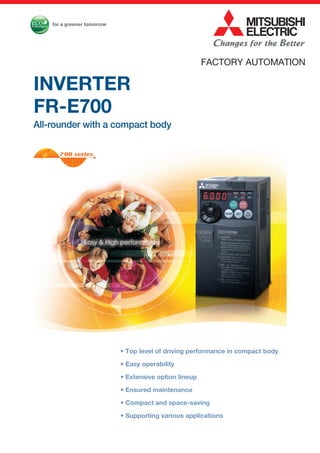
  • 1. • Top level of driving performance in compact body • Easy operability • Extensive option lineup • Ensured maintenance • Compact and space-saving • Supporting various applications INVERTER FR-E700 All-rounder with a compact body FACTORY AUTOMATION
  • 2. 2 Global Player GLOBAL IMPACT OF MITSUBISHI ELECTRIC We bring together the best minds to create the best technologies. At Mitsubishi Electric, we understand that technology is the driving force of change in our lives. By bringing greater comfort to daily life, maximiz- ing the efficiency of businesses and keeping things running across society, we integrate technology and innovation to bring changes for the better. Mitsubishi Electric is involved in many areas including the following Energy and Electric Systems A wide range of power and electrical products from generators to large-scale displays. Electronic Devices A wide portfolio of cutting-edge semiconductor devices for systems and products. Home Appliance Dependable consumer products like air conditioners and home entertain- ment systems. Information and Communication Systems Commercial and consumer-centric equipment, products and systems. Industrial Automation Systems Maximizing productivity and efficiency with cutting-edge automation technology. Through Mitsubishi Electric’s vision, “Changes for the Better“ are possible for a brighter future.
  • 3. 4 9 10 14 21 28 32 40 63 64 79 84 88 89 3 Features Connection example Standard Specifications Outline Dimension Drawings Terminal Connection Diagram, Terminal Specification Explanation Operation panel, Parameter unit, FR Configurator Parameter List Explanations of Parameters Protective Functions Option and Peripheral Devices Precautions for Operation/Selection, Precautions for Peripheral Device Selection Application to Motor Main Differences and Compatibilities with the FR-E500 Series Warranty, Inquiry Contents
  • 4. The inverter became more powerful. 1 Top level of driving performance in compact body (1) High torque 200%/0.5Hz is realized by Advanced magnetic flux vector control (3.7K or less) By the advancement of General-purpose magnetic flux vector control to Advanced magnetic flux vector control, top level of driving performance became possible. Since V/F control and General-purpose magnetic flux vector control operations are available, operation after replacement of the conventional model (FR-E500 series) is ensured. For the 5.5K to 15K, 150%/0.5Hz torque is realized. Evolution in all functionsEvolution in all functionsEvolution in all functionsEvolution in all functions Many kinds of three phase induction motors can be optimally controlled with Mitsubishi's original "non-rotation" auto tuning function. High precision tuning is enabled even when a test operation of a machine cannot be performed at parameter adjustment. Advanced auto tuning Short time overload capacity is increased to 200% 3s (200% 0.5s for the conventional model). Overcurrent trip is less likely to occur. Improved torque limit/current limit function provides a machine protection, load limit, and stop-on-contact operation. (2) Short time overload capacity is increased (200% 3s) (3) Torque limit/current limit function Using the torque limit function, machine breakage from overload can be avoided. For example, edge chipping of a tool can be avoided. When a bogie runs over a bump, the impact can be beared by this function. Speed/torque characteristics example FR-E720-3.7K (SC) (NF) (NC) (Advanced magnetic flux vector control) SF-JR 4P 3.7kW -200% -100% 0 100% 200% 500 1000 3Hz 30Hz 60Hz Speed (r/min) 1500 2000 Load torque (%) Advanced magnetic flux vector control is ideal for a lift in an automated-storage system which requires high torque at low speed. (4) Improved regeneration capability A brake transistor is built-in to the 0.4K to 15K. Connecting an optional brake resistor increases regeneration capability. 4
  • 5. Excellent usability Usability was thoroughly pursued. 2 Setting dial is the feature of Mitsubishi inverters. •Displayed numbers can be jumped by turning the setting dial quickly, and numbers can be changed one by one by turning it slowly, enabling speedy parameter setting. •The nonslip setting dial is easier to turn. (1) Improved setting dial Press and button simultaneously (0.5s). Turn to select operation method. Press to set. According to the desired command sources for start frequency and speed, Pr.79 can be set in simple steps. (2) Easy setting mode Settingis completed An USB connector (mini-B connector) is provided as standard. The inverter can be easily connected without a USB-RS-485 converter. Wizard (interactive) function of FR Configurator (inverter setup software) provides setting support. In addition, a high-speed graph function with USB enables high speed sampling display. (3) With a provided USB connector, setting is easily done from a personal computer using FR Configurator Inverter FR Configurator Acceleration/deceleration pattern setting Acceleration/deceleration time setting Parameter list display Expanded advanced operability with USB and FR Configurator High speed graph function USB cable Mini-B connector Setting wizard function (example: acceleration/deceleration time setting) Optional enclosure surface operation panel (FR-PA07) can be connected. In addition, an operation panel for conventional model (FR-E500 series) can be connected. (5) Parameter unit FR-PU07/ FR-PU07BB(-L) (option) The FR-PU07/FR-PU07BB(-L), an optional parameter unit, can be connected as well. A parameter unit connection cable (FR-CB20 ) is separately required. (Parameter unit connection cable FR-CB203 (3m) is enclosed with FR-PU07BB(-L).) •Setting such as direct input method with a numeric keypad, operation status indication, and help function are useful. Thedisplaylanguagecanbeselectedfrom8languages. •Parameter settings of maximum of three inverters can be stored. •A battery pack type (FR-PU07BB(-L)) allows parameter setting and parameter copy without powering on the inverter. Easy/powerful compact inverterEasy/powerful compact inverterEasy/powerful compact inverterEasy/powerful compact inverter Operation method Panel display Start command Speedcommand Monitor LED RUN button External terminal STF/STR External terminal STF/STR Setting dial RUN button PU Blinking Blinking BlinkingON Blinking ON EXT PU EXT PU EXT PU EXT 1-97 2-97 3-97 4-97 Analog voltage input Setting dial Analog voltage input BlinkingBlinking and flicker. (4) Enclosure surface operation panel FR-PA07 (option) BlinkingBlinking The operation panel of the inverter cannot be removed. A parameter unit connection cable (FR-CB20 ) is separately required. To use a parameter unit with battery pack outside Japan, order the FR-PU07BB-L (model indicated with "L" at the end). •Features •Standard Specifications •Outline Dimension Drawings •Terminal Connection Diagram •Terminal Specification Explanation •Operation panel •Parameter unit •FR Configurator •Parameter List •Explanations of Parameters •Protective Functions •Option and Peripheral Devices •Precautions for Operation/Selection •Precautions for Peripheral Device Selection •Application to Motor •Warranty •Main Differences and Compatibilities with the FR-E500 Series •Service •International FA Center •Connection example 5
  • 6. Terminal card Enhanced expandability Mitsubishi inverters offer the expandability that answers to every need 3 Compact and space saving Compact design expands flexibility of enclosure design. 4 (1) A variety of plug-in options are mountable Plug-in options supporting digital input, analog output extension, and a variety of communications provide extended functions which is almost equivalent to the FR-A700 series. (One type of plug-in option can be mounted.) (3) Control terminals are selectable according to applications (1) Compact body with high performance function Installation size is the same as the conventional mode (FR-E500 series) in consideration of intercompatibility. (7.5K or less) (2) Side by side installation saves space Space can be saved by side by side no clearance installation*. (4) Various kinds of networks are supported •EIA-485 (RS-485), MODBUS® RTU (equipped as standard), CC-Link, PROFIBUS-DP, DeviceNet™ , LONWORKS® (option) •Network-compatible inverters, the CC-Link communication model (FR-E700-NC) and the FL remote communication model (FR-E700-NF), are also available. (5) Environment-conscious filter options •Filterpack FR-BFP2 (the package of the power factor improving DC reactor, common mode choke, and capacitive filter) is available for compliance with the Japanese harmonic suppression guidelines. •A noise filter option for compliance with the EMC Directive (EN61800-3 2nd Environment Category C3) is also available. Plug-in option Plug-in option dedicated front cover Compatible Plug-in Options •FR-A7AX (E kit) ... 16-bit digital input •FR-A7AY (E kit) ... Digital output Extension analog output •FR-A7AR (E kit) ... Relay output •FR-E7DS ............ 24VDC input*1 •FR-A7NC (E kit) ...CC-Link •FR-A7ND (E kit) ...DeviceNet •FR-A7NP (E kit) ...PROFIBUS-DP •FR-A7NL (E kit) ...LONWORKS FR-E720-0.2K FR-E520-0.2K The FR-A7 E kit can be used for the standard control circuit terminal model only. For the safety stop function model, use an FR-A7 and a separate dedicated front cover. 128mm For the customers who need more than the standard terminals, the control terminal option, RS-485 2 port terminal block, is available. A terminal card is removable and can be easily replaced from a standard terminal card. *: Use the inverter at the surrounding air temperature of 40˚C or less. [For the standard control circuit terminal model, order the FR-A7 E kit, which contains an option board FR-A7 and its dedicated front cover.] (2) Safety stop function (FR-E700-SC/NF/NC) •Spring clamp terminals are adopted as control circuit terminals. Spring clamp terminals are highly reliable and can be easily wired. •The FR-E700-SC series is compliant to the EU Machinery Directive without the addition of previously required external devices. Operation of an external Emergency Stop device results in a highly reliable immediate shutoff of the D700's output to the motor. This safety stop function conforms to the following standards. EN ISO 13849-1 Category 3 / PLd EN62061 / IEC61508 SIL2 Provided by the user (present) FR-D700 Safety function is equipped Emergency stop Emergency stop For conventional model... Two MCs were necessary For conventional model... Two MCs were necessary •High cost •Maintenance of two MCs was necessary •Installation space was necessary •Magnetic contactor (MC) •Emergency stop wiring Only one MC is recommended instead of two. Although MC is not required for the safety stop function. Only one MC is recommended instead of two. Although MC is not required for the safety stop function. •Cost reduction •Maintenance of one MC •Installation space is reduced *: Approved safety relay unit * Mitsubishi magnetic contactors •Offer a selection of small frames •Offer a line-up of safety contactors •Support with low-level load (auxiliary contact) •Support many international regulations as a standard model Refer to page 77 for the selection. *1: This option is available for the safety stop function model only. The dedicated front cover is enclosed with the option. 6
  • 7. Ensured maintenance 700 series are the pioneer of long life and high reliability. 5 Full of useful functions6 •The design life of the cooling fan has been extended to 10 years*1 . The life of the fan can be further extended utilizing the it’s ON/OFF control. •The design life of the capacitors has been extended to 10 years*1 *2 by adopting a capacitor that endures about 5000 hours at 105°C surrounding air temperature. (1) Long-life design A cooling fan is provided on top of the inverter for all capacities requiring a cooling fan*. A cooling fan can be easily replaced without disconnecting main circuit wires. (3) Easy replacement of cooling fan Since a wiring cover can be installed after wiring, wiring work is easily done. (4) Combed shaped wiring cover Wiring of the control circuit when replacing the same series inverter can be done by changing the terminal block. (5) Removable control terminal block •Degrees of deterioration of main circuit capacitor, control circuit capacitor, and inrush current limit circuit can be monitored. •Trouble can be avoided with the self-diagnostic alarm*4 that is output when the life span is near. *4: Any one of main circuit capacitor, control circuit capacitor, inrush current limit circuit or cooling fan reaches the output level, an alarm is output. Capacity of the main circuit capacitor can be measured by setting parameter at a stop and turning the power from off to on. Measuring the capacity enables an alarm to be output. *: The inverter may trip and the motor may coast depending on the load condition. Detection of coasting speed (frequency search function) prevents the motor speed from decreasing at a restart, starting the motor smoothly with less output current. *1: Surrounding air temperature : annual average 40˚C (free from corrosive gas, flammable gas, oil mist, dust and dirt) Since the design life is a calculated value, it is not a guaranteed value. *2: Output current : 80% of the inverter rated current *: Cooling fans are equipped with FR-E720-1.5K (SC) (NF) (NC) or more, FR-E740-1.5K (SC) (NF) (NC) or more, and FR-E720S-0.75K (SC) or more. (2) Leading life check function •Automatic restart after instantaneous power failure function with frequency search •Brake sequence mode is useful for mechanical brake control of a lift. •Regeneration avoidance function prevents regenerative overvoltage in a pressing machine. •Main circuit power supply DC input can be connected to DC power supply. •Enhanced I/O terminal function supports switchover of analog input (voltage / current). •Password function is effective for parameter setting protection. and so on •Power-failure deceleration stop function/operation continuation at instantaneous power failure function The motor can be decelerated to a stop when a power failure or undervoltage occurs to prevent the motor from coasting. This function is useful to stop a motor at power failure as a fail safe of machine tool, etc. With the new operation continuation function at instantaneous power failure, the motor continues running without coasting even if an instantaneous power failure occurs during operation. •Estimated service lifespan of the long-life parts Components Cooling fan Main circuit smoothing capacitor Printed board smoothing capacitor Estimated lifespan of the FR-E700 10 years 10 years 10 years Guideline of JEMA*3 2 to 3 years 5 years 5 years *3: Excerpts from “Periodic check of the transistorized inverter” of JEMA (Japan Electrical Manufacturer’s Association) FR-E500 series FR-E700 series Input voltage Output frequency Motor speed Output current Input voltage Output frequency Motor speed Output current Enhanced functions for all sorts of applications Energy saving for fans and pumps •Load pattern selection (Pr. 14) Optimal output characteristics (V/F characteristics) for application or load characteristics can be selected. •Optimum excitation control (Pr. 60) With Optimum excitation control to achieve the highest motor efficiency, further energy saving can be achieved. Refer to page 62 7 FeaturesOptionsInstructionsMotorCompatibilityWarrantyInquiry Connection example Standard Specifications Operationpanel Parameterunit FRConfigurator Parameter List Protective Functions Explanations of Parameters TerminalConnection Diagram TerminalSpecification Explanation Outline Dimension Drawings
  • 8. FR-E720 -0.1K Lineup :Available models :Not available :Available models :Not available Inverter Model Inverter Capacity 0.1K 0.2K 0.4K 0.75K 1.5K 2.2K 3.7K 5.5K 7.5K 11K 15K Three-phase 200V FR-E720- (SC) Three-phase 400V FR-E740- (SC) Single-phase 200V FR-E720S- (SC)* Single-phase 100V FR-E710W-* *:Output of the single-phase 200V and single-phase 100V input specifications is three-phase 200V. Inverter Model Inverter Capacity 0.1K 0.2K 0.4K 0.75K 1.5K 2.2K 3.7K 5.5K 7.5K 11K 15K Three-phase 200V FR-E720- NF/NC Three-phase 400V FR-E740- NF/NC Symbol 1 2 4 Voltage 100V class 200V class 400V class Symbol None SC NF NC Control circuit terminal specification Standard control circuit terminal model (screw type) Safety stop function model FL remote communication model CC-Link communication model Symbol 0.1K to 15K Inverter Capacity Represents the inverter capacity "kW". Symbol None S W Number of Power Phases Three-phase input Single-phase input Single-phase input (double voltage output) Complies with UL, cUL, and EC Directives (CE marking), and the Radio Waves Act (South Korea) (KC marking). It is also certified as compliant with the Eurasian Conformity (EAC). The single-phase 100V power input model is not compliant with the EMC Directive. The inverters are compliant with the EU RoHS Directive (Restriction of the Use of Certain Hazardous Substances in Electrical and Electronic Equipment), friendly to people and to the environment. 8
  • 9. EMC filter (ferrite core) (FR-BSF01, FR-BLF) Motor Earth (Ground) EMC filter (ferrite core)*1 (FR-BSF01, FR-BLF) P/+ P/+ PR PR High power factor converter (FR-HC2) Power regeneration common converter (FR-CV) Resistor unit (FR-BR) Discharging resistor (GZG, GRZG) Earth (Ground) Install a noise filter to reduce the electromagnetic noise generated from the inverter. Effective in the range from about 1MHz to 10MHz. A wire should be wound four turns at a maximum. AC power supply Use within the permissible power supply specifications of the inverter. To ensure safety, use a moulded case circuit breaker, earth leakage circuit breaker or magnetic contactor to switch power ON/OFF. Enclosure surface operation panel (FR-PA07) Connect a connection cable (FR-CB2) to the PU connector to use the FR-PA07, FR-PU07/FR-PU07BB(-L).*2 USB connector A personal computer and an inverter can be connected with a USB (Ver1.1) cable. Molded case circuit breaker (MCCB) or earth leakage current breaker (ELB), fuse The breaker must be selected carefully since an in-rush current flows in the inverter at power on. Magnetic contactor (MC) Install the magnetic contactor to ensure safety. Do not use this magnetic contactor to start and stop the inverter. Doing so will cause the inverter life to be shorten. Reactor (FR-HAL, FR-HEL option) Install reactors to suppress harmonics and to improve the power factor. A reactor (option) is required when installing the inverter near a large power supply system (500kVA or more). The inverter may be damaged if you do not use reactors. Select the reactor according to the model. Remove the jumpers across terminals P/+ - P1 to connect the DC reactor. Devices connected to the output Do not install a power factor correction capacitor, surge suppressor or radio noise filter on the output side of the inverter. When installing a moulded case circuit breaker on the output side of the inverter, contact each manufacturer for selection of the moulded case circuit breaker. Earth (Ground) To prevent an electric shock, always earth (ground) the motor and inverter. For reduction of induction noise from the power line of the inverter, it is recommended to wire the earth (ground) cable by returning it to the earth (ground) terminal of the inverter. R/L1 S/L2 T/L3P1P/+ N/-P/+ U W Brake unit (FR-BU2) P/+ PR V Power supply harmonics can be greatly suppressed. Install this as required.*2 Great braking capability is obtained. Install this as required.*2 The regenerative braking capability of the inverter can be exhibited fully. Install this as required. Install a noise filter to reduce the electromagnetic noise generated from the inverter. Effective in the range from about 1MHz to 10MHz. When more wires are passed through, a more effective result can be obtained. A wire should be wound four turns or more. EMC filter (capacitor)*1 (FR-BIF) Reduces the radio noise. Connection example *1: Filterpack (FR-BFP2), which contains DC reactor and noise filter in one package, is also available. *2: The converter is used for the standard control circuit terminal model or the safety stop function model. DC reactor (FR-HEL)*1 AC reactor (FR-HAL) Brake resistor (FR-ABR, MRS, MYS) Braking capability can be improved. (0.4K or more) Always install a thermal relay when using a brake resistor whose capacity is 11K or more. Parameter unit (FR-PU07/FR-PU07BB(-L)) S1 S2 PC Approved safety relay module Required for compliance with safety standard. The module can be used for the safety stop function model, FL remote communication model, and CC-Link communication model. FeaturesOptionsInstructionsMotorCompatibilityWarrantyInquiry Connection example Standard Specifications Operationpanel Parameterunit FRConfigurator Parameter List Protective Functions Explanations of Parameters TerminalConnection Diagram TerminalSpecification Explanation Outline Dimension Drawings 9
  • 10. 10 Standard specifications  Three-phase 200V power supply  Three-phase 400V power supply  The applicable motor capacity indicated is the maximum capacity applicable for use of the Mitsubishi 4-pole standard motor.  The rated output capacity indicated assumes that the output voltage is 230V for three-phase 200V class and 440V for three-phase 400V class.  The % value of the overload current rating indicated is the ratio of the overload current to the inverter's rated output current. For repeated duty, allow time for the inverter and motor to return to or below the temperatures under 100% load.  The maximum output voltage does not exceed the power supply voltage. The maximum output voltage can be changed within the setting range. However, the pulse voltage value of the inverter output side voltage remains unchanged at about that of the power supply.  The braking torque indicated is a short-duration average torque (which varies with motor loss) when the motor alone is decelerated from 60Hz in the shortest time and is not a continuous regenerative torque. When the motor is decelerated from the frequency higher than the base frequency, the average deceleration torque will reduce. Since the inverter does not contain a brake resistor, use the optional brake resistor when regenerative energy is large. A brake unit (FR-BU2) may also be used. (Option brake resisitor cannot be used for 0.1K and 0.2K.)  The power supply capacity varies with the value of the power supply side inverter impedance (including those of the input reactor and cables).  Setting 2kHz or more in Pr. 72 PWM frequency selection to perform low acoustic noise operation in the surrounding air temperature exceeding 40°C, the rated output current is the value in parenthesis.   Connect DC power supply to terminal P/+ and N/-. Connect the plus side of the power supply to terminal P/+ and minus side to terminal N/-.  When energy is regenerated from the motor, the voltage between terminals P/+ and N/- may rise to 415V of more for the 200V class, or 830V or more for the 400V class. Use a DC power supply resistant to the regenerative voltage/energy.  Although the FR-E700 series has the built-in inrush current limit circuit, select the DC power supply considering the inrush current at powering ON as the inrush current four times of the rated inverter flows at powering ON.  Since the power supply capacity depends on the output impedance of the power, select the power supply capacity which has enough allowance according to the AC power supply system capacity.  The safety stop function model is indicated with SC.  "NF" indicates the FL remote communication function model.  "NC" indicates the CC-Link communication model. Rating Model FR-E720-K(SC)(NF)(NC) 0.1 0.2 0.4 0.75 1.5 2.2 3.7 5.5 7.5 11 15 Applicable motor capacity (kW) 0.1 0.2 0.4 0.75 1.5 2.2 3.7 5.5 7.5 11 15 Output Rated capacity (kVA) 0.3 0.6 1.2 2.0 3.2 4.4 7.0 9.5 13.1 18.7 23.9 Rated current (A) 0.8 (0.8) 1.5 (1.4) 3 (2.5) 5 (4.1) 8 (7) 11 (10) 17.5 (16.5) 24 (23) 33 (31) 47 (44) 60 (57) Overload current rating 150% 60s, 200% 3s (inverse-time characteristics) Rated voltage Three-phase 200 to 240V Regenerative braking torque 150% 100% 50% 20% Powersupply Rated input AC (DC) voltage/frequency Three-phase 200 to 240V 50Hz/60Hz (283 to 339VDC) Permissible AC (DC) voltage fluctuation 170 to 264V 50Hz/60Hz (240 to 373VDC) Permissible frequency fluctuation ±5% Power supply capacity (kVA) 0.4 0.8 1.5 2.5 4.5 5.5 9 12 17 20 28 Protective structure (JEM1030) Enclosed type (IP20) Open type (IP00) for the FL remote communication model and CC-Link communication model. Cooling system Self-cooling Forced air cooling Approximate mass (kg) 0.5 0.5 0.7 1.0 1.4 1.4 1.7 4.3 4.3 6.5 6.5 Model FR-E740-K(SC)(NF)(NC) 0.4 0.75 1.5 2.2 3.7 5.5 7.5 11 15 Applicable motor capacity (kW) 0.4 0.75 1.5 2.2 3.7 5.5 7.5 11 15 Output Rated capacity (kVA) 1.2 2.0 3.0 4.6 7.2 9.1 13.0 17.5 23.0 Rated current (A) 1.6 (1.4) 2.6 (2.2) 4.0 (3.8) 6.0 (5.4) 9.5 (8.7) 12 17 23 30 Overload current rating 150% 60s, 200% 3s (inverse-time characteristics) Rated voltage Three-phase 380 to 480V Regenerative braking torque 100% 50% 20% Powersupply Rated input voltage/frequency Three-phase 380 to 480V 50Hz/60Hz (537 to 679VDC) Permissible AC voltage fluctuation 325 to 528V 50Hz/60Hz (457 to 740VDC) Permissible frequency fluctuation ±5% Power supply capacity (kVA) 1.5 2.5 4.5 5.5 9.5 12 17 20 28 Protective structure (JEM1030) Enclosed type (IP20) Open type (IP00) for the FL remote communication model and CC-Link communication model. Cooling system Self-cooling Forced air cooling Approximate mass (kg) 1.4 1.4 1.9 1.9 1.9 3.2 3.2 6.0 6.0 2
  • 11. FeaturesOptionsInstructionsMotorCompatibilityWarrantyInquiry Connection example Standard Specifications Operationpanel Parameterunit FRConfigurator Parameter List Protective Functions Explanations of Parameters TerminalConnection Diagram TerminalSpecification Explanation Outline Dimension Drawings 11  Single-phase 200V power supply  Single-phase 100V power supply  The applicable motor capacity indicated is the maximum capacity applicable for use of the Mitsubishi 4-pole standard motor.  The rated output capacity indicated assumes that the output voltage is 230V.  The % value of the overload current rating indicated is the ratio of the overload current to the inverter's rated output current. For repeated duty, allow time for the inverter and motor to return to or below the temperatures under 100% load. If the automatic restart after instantaneous power failure function (Pr. 57) or power failure stop function (Pr. 261) is set and power supply voltage is low while load becomes bigger, the bus voltage decreases to power failure detection level and load of 100% or more may not be available.  The maximum output voltage does not exceed the power supply voltage. The maximum output voltage can be changed within the setting range. However, the pulse voltage value of the inverter output side voltage remains unchanged at about that of the power supply.  The braking torque indicated is a short-duration average torque (which varies with motor loss) when the motor alone is decelerated from 60Hz in the shortest time and is not a continuous regenerative torque. When the motor is decelerated from the frequency higher than the base frequency, the average deceleration torque will reduce. Since the inverter does not contain a brake resistor, use the optional brake resistor when regenerative energy is large. A brake unit (FR-BU2) may also be used. (Option brake resisitor cannot be used for 0.1K and 0.2K.)  The power supply capacity varies with the value of the power supply side inverter impedance (including those of the input reactor and cables).  Setting 2kHz or more in Pr. 72 PWM frequency selection to perform low acoustic noise operation with the surrounding air temperature exceeding 40°C, the rated output current is the value in parenthesis.  For single-phase 100V power input model, the maximum output voltage is twice the amount of the power supply voltage and cannot be exceeded.  In a single-phase 100V power input model, the output voltage may fall down when the load is heavy, and larger output current may flow compared to a threephase input model. Use the motor with less load so that the output current is within the rated motor current range.  The safety stop function model is indicated with SC. Model FR-E720S-K(SC) 0.1 0.2 0.4 0.75 1.5 2.2 Applicable motor capacity (kW) 0.1 0.2 0.4 0.75 1.5 2.2 Output Rated capacity (kVA) 0.3 0.6 1.2 2.0 3.2 4.4 Rated current (A) 0.8 (0.8) 1.5 (1.4) 3.0 (2.5) 5.0 (4.1) 8.0 (7.0) 11.0 (10.0) Overload current rating 150% 60s, 200% 3s (inverse-time characteristics) Rated voltage Three-phase 200 to 240V Regenerative braking torque 150% 100% 50% 20% Powersupply Rated input AC voltage/frequency Single-phase 200 to 240V 50Hz/60Hz Permissible AC voltage fluctuation 170 to 264V 50Hz/60Hz Permissible frequency fluctuation Within ±5% Power supply capacity (kVA) 0.5 0.9 1.5 2.5 4.0 5.2 Protective structure (JEM1030) Enclosed type (IP20) Cooling system Self-cooling Forced air cooling Approximate mass (kg) 0.6 0.6 0.9 1.4 1.5 2.0 Model FR-E710W-K 0.1 0.2 0.4 0.75 Applicable motor capacity (kW) 0.1 0.2 0.4 0.75 Output Rated capacity (kVA) 0.3 0.6 1.2 2.0 Rated current (A) 0.8 (0.8) 1.5 (1.4) 3.0 (2.5) 5.0 (4.1) Overload current rating 150% 60s, 200% 3s (inverse-time characteristics) Rated voltage Three-phase 200 to 230V,  Regenerative braking torque 150% 100% Powersupply Rated input AC voltage/frequency Single-phase 100 to 115V 50Hz/60Hz Permissible AC voltage fluctuation 90 to 132V 50Hz/60Hz Permissible frequency fluctuation Within ±5% Power supply capacity (kVA) 0.5 0.9 1.5 2.5 Protective structure (JEM1030) Enclosed type (IP20) Cooling system Self-cooling Approximate mass (kg) 0.6 0.7 0.9 1.5 2
  • 12. 12 Common specifications Controlspecifications Control method Soft-PWM control/high carrier frequency PWM control (V/F control, Advanced magnetic flux vector control, General-purpose magnetic flux vector control, Optimum excitation control are available) Output frequency range 0.2 to 400Hz Frequency setting resolution Analog input  0.06Hz/60Hz (terminal2, 4: 0 to 10V/10bit) 0.12Hz/60Hz (terminal2, 4: 0 to 5V/9bit) 0.06Hz/60Hz (terminal4: 0 to 20mA/10bit) Digital input 0.01Hz Frequency accuracy Analog input  Within 0.5% of the max. output frequency (25°C 10°C) Digital input Within 0.01% of the set output frequency Voltage/frequency characteristics Base frequency can be set from 0 to 400Hz, Constant-torque/variable torque pattern can be selected Starting torque 200% or more (at 0.5Hz)...when Advanced magnetic flux vector control is set (3.7K or less) Torque boost Manual torque boost Acceleration/deceleration time setting 0.01 to 360s, 0.1 to 3600s (acceleration and deceleration can be set individually), linear or S-pattern acceleration/ deceleration modes are available. DC injection brake Operation frequency (0 to 120Hz), operation time (0 to 10s), operation voltage (0 to 30%) can be changed. Stall prevention operation level Operation current level can be set (0 to 200% adjustable), whether to use the function or not can be selected Operationspecifications Frequency setting signal Analog input  Two terminals Terminal 2: 0 to 10V, 0 to 5V can be selected Terminal 4: 0 to 10V, 0 to 5V, 4 to 20mA can be selected Digital input Input from the operation panel or parameter unit. (Instead of the input from the parameter unit, input via the FL remote network is available for the FL remote communication model, and input via the CC-Link network is available for the CC-Link communication model.) Frequency setting increment is selectable. 4 digit BCD or 16bit binary data (when the option FR-A7AX E kit is used) Start signal Forward and reverse rotation or start signal automatic self-holding input (3-wire input) can be selected. Input signal (Standard control circuit terminal model: Seven terminals Safety stop function model: Six terminals) The following signals can be assigned to Pr. 178 to Pr.184 (input terminal function selection): multi-speed selection, remote setting, stop-on contact selection, second function selection, terminal 4 input selection, JOG operation selection, PID control valid terminal, brake opening completion signal, external thermal input, PU-External operation switchover, V/F switchover, output stop, start self-holding selection, forward rotation, reverse rotation command, inverter reset, PU-NET operation switchover, External-NET operation switchover, command source switchover, inverter operation enable signal, and PU operation external interlock Operational functions Maximum/minimum frequency setting, frequency jump operation, external thermal relay input selection, automatic restart after instantaneous power failure operation, forward/reverse rotation prevention, remote setting, brake sequence, second function, multi-speed operation, stop-on contact control, droop control, regeneration avoidance, slip compensation, operation mode selection, offline auto tuning function, PID control, computer link operation (RS-485) Safety stop function Safety shutoff signal can be input from terminals S1 and S2. (compliant with EN ISO 13849-1 Category 3 / PLd EN62061 / IEC61508 SIL2) Output signal Open collector output (Two terminals) Relay output (One terminal) The following signals can be assigned to Pr.190 to Pr.192 (output terminal function selection): inverter operation, up- to-frequency, overload alarm, output frequency detection, regenerative brake prealarm, electronic thermal relay function prealarm, inverter operation ready, output current detection, zero current detection, PID lower limit, PID upper limit, PID forward/reverse rotation output, brake opening request, fan alarm, heatsink overheat pre- alarm, deceleration at an instantaneous power failure, PID control activated, safety monitor output, safety monitor output2, 24V external power supply operation, during retry, life alarm, current average value monitor, remote output, alarm output, fault output, fault output 3, and maintenance timer alarm Operating status For meter Pulse train output (Max. 2.4kHz: one terminal) The following signals can be assigned to Pr.54 FM terminal function selection: output frequency, motor current (steady), output voltage, frequency setting, motor torque, converter output voltage, regenerative brake duty, electronic thermal relay function load factor, output current peak value, converter output voltage peak value, reference voltage output, motor load factor, PID set point, PID measured value, output power Pulse train output (1440 pulses/s/full scale) Indication Operation panel Parameter unit (FR-PU07) Operating status The following operating status can be displayed: output frequency, motor current (steady), output voltage, frequency setting, cumulative energization time, actual operation time, motor torque, converter output voltage, regenerative brake duty, electronic thermal relay function load factor, output current peak value, converter output voltage peak value, motor load factor, PID set point, PID measured value, PID deviation, inverter I/O terminal monitor, I/O terminal option monitor, output power, cumulative power, motor thermal load factor, and inverter thermal load factor. Fault record Fault record is displayed when a fault occurs. Past 8 fault records (output voltage/current/frequency/cumulative energization time right before the fault occurs) are stored Interactive guidance Function (help) for operation guide Protective/warning function Protective functions Overcurrent during acceleration, overcurrent during constant speed, overcurrent during deceleration, overvoltage during acceleration, overvoltage during constant speed, overvoltage during deceleration, inverter protection thermal operation, motor protection thermal operation, heatsink overheat, input phase failure, stall prevention stop, output side earth (ground) fault overcurrent at start, output short circuit, output phase failure, external thermal relay operation, option fault , parameter error, internal board fault, PU disconnection, retry count excess , CPU fault, brake transistor alarm, inrush resistance overheat, communication error, analog input error, USB communication error, brake sequence error 4 to 7, safety circuit fault Warning functions Fan alarm, overcurrent stall prevention, overvoltage stall prevention, PU stop, parameter write error, regenerative brake prealarm, electronic thermal relay function prealarm, maintenance output, undervoltage, operation panel lock, password locked, inverter reset, safety stop, 24V external power supply operation Environment Surrounding air temperature -10°C to +50°C (non-freezing) Ambient humidity 90%RH or less (non-condensing) Storage temperature -20°C to +65°C Atmosphere Indoors (without corrosive gas, flammable gas, oil mist, dust and dirt etc.) Altitude/vibration Maximum 1000m above sea level, 5.9m/s2 or less at 10 to 55Hz (directions of X, Y, Z axes)
  • 13. FeaturesOptionsInstructionsMotorCompatibilityWarrantyInquiry Connection example Standard Specifications Operationpanel Parameterunit FRConfigurator Parameter List Protective Functions Explanations of Parameters TerminalConnection Diagram TerminalSpecification Explanation Outline Dimension Drawings 13  As the FR-E720-0.1K(SC)(NF)(NC) to 0.75K(SC)(NF)(NC), FR-E740-0.4K(SC)(NF)(NC) and 0.75K(SC)(NF)(NC), FR-E720S-0.1K(SC) to 0.4K(SC), FR-E710W-0.1K to 0.75K are not provided with the cooling fan, this alarm does not function.  This function is available for the safety stop function model and the CC- Link communication model.  This function is not available for the standard control circuit terminal model.  This operation guide is only available with option parameter unit (FR- PU07).  This protective function is not available in the initial status.  This protective function is available with the three-phase power input model only.  When using the inverters at the surrounding air temperature of 40°C or less, the inverters can be installed closely attached (0cm clearance).  Temperatures applicable for a short time, e.g. in transit.  This function is not available for the FL remote communication model.  The FL remote communication model and the CC-Link communication model have only one open collector output terminal. For the FL remote communication model, the terminal is used only for the safety monitor output signal (not selectable).  This function is available for the safety stop function model with the FR- E7DS, FL remote communication model, and CC-Link communication model.  This function is not available for the CC-Link communication model.  For the CC-Link communication model, input signals can be assigned to the input virtual terminals for CC-Link communication.
  • 14. 14 Outline Dimension Drawings FR-E720-0.1K(SC) to 0.75K(SC) FR-E720S-0.1K(SC) to 0.4K(SC) FR-E710W-0.1K to 0.4K (Unit: mm) 4 D D1 4 D2 ∗ D1 5 68 56 51185 128 φ5 hole Capacity plate Rating plate Rating plate Inverter Model D D1 D2  FR-E720-0.1K, 0.2K FR-E720S-0.1K, 0.2K FR-E710W-0.1K 80.5 10 95.6 FR-E720-0.1KSC, 0.2KSC FR-E720S-0.1KSC, 0.2KSC 86.5 108.1 FR-E710W-0.2K 110.5 10 125.6 FR-E720-0.4K 112.5 42 127.6 FR-E720-0.4KSC 118.5 140.1 FR-E720-0.75K 132.5 62 147.6 FR-E720-0.75KSC 138.5 160.1 FR-E720S-0.4K FR-E710W-0.4K 142.5 42 157.6 FR-E720S-0.4KSC 148.5 170.1  When the FR-A7NC (E kit) is used for the standard control terminal model, or the FR-A7NC and the FR-A7NC E kit safety cover SC is used for the safety stop function model, a terminal block protrudes forward, increasing the depth by about 2mm (up to 2.8mm). When used with the plug-in option
  • 15. FeaturesOptionsInstructionsMotorCompatibilityWarrantyInquiry Operationpanel Parameterunit FRConfigurator Parameter List Protective Functions Explanations of Parameters TerminalConnection Diagram TerminalSpecification Explanation Outline Dimension Drawings Connection example Standard Specifications 15 FR-E720-1.5K(SC), 2.2K(SC) FR-E720S-0.75K(SC), 1.5K(SC) FR-E710W-0.75K FR-E720-3.7K(SC) (Unit: mm) (Unit: mm) 2-φ5 hole 96 108 51185 128 5 D 5 D2*2 5 Capacity plate Rating plate Rating plate D1 D1 *1 When used with the plug-in option  FR-E710W-0.75K are not provided with the cooling fan. Inverter Model D D1 D2  FR-E720-1.5K, 2.2K FR-E720S-0.75K 135.5 60 150.6 FR-E720-1.5KSC, 2.2KSC FR-E720S-0.75KSC 141.5 163.1 FR-E720S-1.5K 161 176.1 FR-E720S-1.5KSC 167 188.6 FR-E710W-0.75K 155 54 170.1  When the FR-A7NC (E kit) is used for the standard control terminal model, or the FR-A7NC and the FR-A7NC E kit safety cover SC is used for the safety stop function model, a terminal block protrudes forward, increasing the depth by about 2mm (up to 2.8mm). 5 158 170 51185 128 2-φ5 hole 5 D D1 * 5 Capacity plate Rating plate Rating plate 66.5 66.5 When used with the plug-in option Inverter Model D D1  FR-E720-3.7K 142.5 157.6 FR-E720-3.7KSC 148.5 170.1  When the FR-A7NC (E kit) is used for the standard control terminal model, or the FR-A7NC and the FR-A7NC E kit safety cover SC is used for the safety stop function model, a terminal block protrudes forward, increasing the depth by about 2mm (up to 2.8mm).
  • 16. 16 FR-E720-5.5K(SC) to 15K(SC) (Unit: mm) 6 W1 W 82448 260 D3 D D3 D1* 2-φ6hole W2 D2 D2 Capacity plate Rating plate Rating plate When used with the plug-in option Inverter Model W W1 W2 D D1  D2 D3 FR-E720-5.5K, 7.5K 180 164 180 165 180.1 71.5 10 FR-E720-5.5KSC, 7.5KSC 171 192.6 FR-E720-11K, 15K 220 195 211 190 205.1 84.5 10.5 FR-E720-11KSC, 15KSC 196 217.6  When the FR-A7NC (E kit) is used for the standard control terminal model, or the FR-A7NC and the FR-A7NC E kit safety cover SC is used for the safety stop function model, a terminal block protrudes forward, increasing the depth by about 2mm (up to 2.8mm).
  • 17. FeaturesOptionsInstructionsMotorCompatibilityWarrantyInquiry Operationpanel Parameterunit FRConfigurator Parameter List Protective Functions Explanations of Parameters TerminalConnection Diagram TerminalSpecification Explanation Outline Dimension Drawings Connection example Standard Specifications 17 FR-E740-0.4K(SC) to 3.7K(SC) FR-E720S-2.2K(SC) FR-E740-5.5K(SC), 7.5K(SC) (Unit: mm) (Unit: mm) 5 D D1 5 128 140 13866 2-φ5 hole 150 5 D2 ∗2 D1 ∗1 ∗1 Rating plate Rating plate Capacity plate When used with the plug-in option  FR-E740-0.4K, 0.75K are not provided with the cooling fan. Inverter Model D D1 D2  FR-E740-0.4K, 0.75K 114 39 129.1 FR-E740-0.4KSC, 0.75KSC 120 141.6 FR-E740-1.5K to 3.7K 135 60 150.1 FR-E740-1.5KSC to 3.7KSC 141 162.6 FR-E720S-2.2K 155.5 170.6 FR-E720S-2.2KSC 161.5 183.1  When the FR-A7NC (E kit) is used for the standard control terminal model, or the FR-A7NC and the FR-A7NC E kit safety cover SC is used for the safety stop function model, a terminal block protrudes forward, increasing the depth by about 2mm (up to 2.8mm). 2-φ5 hole 13866 150 5 208 220 10 D 68 10 D1∗ 68 Capacity plate Rating plate Rating plate When used with the plug-in option Inverter Model D D1  FR-E740-5.5K, 7.5K 147 162.1 FR-E740-5.5KSC, 7.5KSC 153 174.6  When the FR-A7NC (E kit) is used for the standard control terminal model, or the FR-A7NC and the FR-A7NC E kit safety cover SC is used for the safety stop function model, a terminal block protrudes forward, increasing the depth by about 2mm (up to 2.8mm).
  • 18. 18 FR-E740-11K(SC), 15K(SC) (Unit: mm) 6 195 88 260 244 FAN 10.5 84.5 84.5 D 2-φ6 hole FAN 10.5 D1 * 211 220 Capacity plate Rating plate Rating plate When used with the plug-in option Inverter Model D D1  FR-E740-11K, 15K 190 205.1 FR-E740-11KSC, 15KSC 196 217.6  When the FR-A7NC (E kit) is used for the standard control terminal model, or the FR-A7NC and the FR-A7NC E kit safety cover SC is used for the safety stop function model, a terminal block protrudes forward, increasing the depth by about 2mm (up to 2.8mm).
  • 19. FeaturesOptionsInstructionsMotorCompatibilityWarrantyInquiry Operationpanel Parameterunit FRConfigurator Parameter List Protective Functions Explanations of Parameters TerminalConnection Diagram TerminalSpecification Explanation Outline Dimension Drawings Connection example Standard Specifications 19 FL remote communication model CC-Link communication model D W1 W H1 H (Unit: mm)  Three-phase 200V class  Three-phase 400V class Inverter Model W W1 H H1 D FR-E720-0.1KNF 68 56 128 118 89.5 FR-E720-0.2KNF FR-E720-0.4KNF 121.5 FR-E720-0.75KNF 141.5 FR-E720-1.5KNF 108 96 144.5 FR-E720-2.2KNF FR-E720-3.7KNF 170 158 151.5 FR-E720-5.5KNF 180 164 260 244 174 FR-E720-7.5KNF FR-E720-11KNF 220 195 199 FR-E720-15KNF Inverter Model W W1 H H1 D FR-E740-0.4KNF 140 128 150 138 123 FR-E740-0.75KNF FR-E740-1.5KNF 144FR-E740-2.2KNF FR-E740-3.7KNF FR-E740-5.5KNF 220 208 156 FR-E740-7.5KNF FR-E740-11KNF 195 260 244 199 FR-E740-15KNF D W1 W H1 H (Unit: mm)  Three-phase 200V class  Three-phase 400V class Inverter Model W W1 H H1 D FR-E720-0.1KNC 68 56 128 118 108 FR-E720-0.2KNC FR-E720-0.4KNC 140 FR-E720-0.75KNC 160 FR-E720-1.5KNC 108 96 163 FR-E720-2.2KNC FR-E720-3.7KNC 170 158 170 FR-E720-5.5KNC 180 164 260 244 192.5 FR-E720-7.5KNC FR-E720-11KNC 220 195 217.5 FR-E720-15KNC Inverter Model W W1 H H1 D FR-E740-0.4KNC 140 128 150 138 141.5 FR-E740-0.75KNC FR-E740-1.5KNC 162.5FR-E740-2.2KNC FR-E740-3.7KNC FR-E740-5.5KNC 220 208 174.5 FR-E740-7.5KNC FR-E740-11KNC 195 260 244 217.5 FR-E740-15KNC
  • 20. 20 Parameter unit (option) (FR-PU07) <Outline drawing> <Panel cut dimension drawing> Parameter unit with battery pack (option) (FR-PU07BB) Enclosure surface operation panel (option) (FR-PA07) <Outline drawing> <Panel cut dimension drawing> 6751 40 56.8 57.8 26.5 4-R1 26.5 40 4-φ4 hole (Effective depth of the installation screw hole 5.0) M3 screw *2 Air-bleeding hole 80.3 (14.2) 2.550 (11.45) 25.05 135 83 *1 *1 *1 *1  When installing the FR-PU07 on the enclosure, etc., remove screws or fix the screws to the FR-PU07 with M3 nuts.  Select the installation screw whose length will not exceed the effective depth of the installation screw hole. (Unit: mm) 46.7 135 83 18 6 8.2 46.7 44.7 (Unit: mm) 68 59 22 22 2-M3 screw (Unit: mm)
  • 21. FeaturesOptionsInstructionsMotorCompatibilityWarrantyInquiry Standard Specifications Operationpanel Parameterunit FRConfigurator Parameter List Protective Functions Explanations of Parameters TerminalConnection Diagram TerminalSpecification Explanation Outline Dimension Drawings Connection example 21 Terminal Connection Diagram (1) Standard control circuit terminal model l Note  To prevent a malfunction caused by noise, separate the signal cables more than 10cm from the power cables. Also separate the main circuit wire of the input side and the output side.  After wiring, wire offcuts must not be left in the inverter. Wire offcuts can cause an alarm, failure or malfunction. Always keep the inverter clean. When drilling mounting holes in an enclosure etc., take care not to allow chips and other foreign matter to enter the inverter.  The output of the single-phase power input model is three-phase 200V. Earth (Ground) Motor IM Earth (Ground) Three-phase AC power supply MCCB MC R/L1 P1 P/+ PR N/- S/L2 T/L3 U V W Earth (Ground) *8 Brake resistor (FR-ABR, MRS, MYS type) Install a thermal relay to prevent an overheat and burnout of the brake resistor. (The brake resistor can not be connected to the 0.1K and 0.2K.) *7 A brake transistor is not built-in to the 0.1K and 0.2K. Forward rotation start Reverse rotation start Middle speed High speed Low speed Output stop Reset Control input signals (No voltage input allowed) Contact input common 24VDC power supply (Common for external power supply transistor) STR STF RH RM RL MRS SD PC Relay output Running Frequency detection Open collector output Open collector output common Sink/source common FU RUN SE A B C FM SD Indicator (Frequency meter, etc.)+ - Moving-coil type 1mA full-scale Calibration resistor Frequency setting signals (Analog) 2 0 to 5VDC 10(+5V) 2 3 1 Frequency setting potentiometer 1/2W1kΩ 5(Analog common)*4 Connector for plug-in option connection Option connector *3 Terminal input specifications can be changed by analog input specifications switchover (Pr. 73). *2 When using terminals PC-SD as a 24VDC power supply, take care not to short across terminals PC-SD. PU connector USB connector *9 It is not necessary when calibrating the indicator from the operation panel. *1. DC reactor (FR-HEL) When connecting a DC reactor, remove the jumper across P1 and P/+. Not available for single-phase 100V power input model. Control circuit terminal Main circuit terminal Sink logic Jumper *1 *8 *7 *6 *2 *3 *9 Terminal functions vary with the input terminal assignment (Pr. 178 to Pr. 184) Multi-speed selection Terminal functions vary with the output terminal assignment (Pr. 190 and Pr. 191) Terminal functions vary by Pr. 192 A,B,C terminal function selection SINK SOURCE I V *5 (0 to 10VDC) Voltage/current input switch Main circuit Control circuit Standard control terminal block R RES Relay output (Fault output) Brake unit (Option) Single-phase AC power supply MCCB MC R/L1 S/L2 Single-phase power input *6 Terminal P1 is not available for single-phase 100V power input model. Terminal 4 input (Current input) (+) (-) 4 4 to 20mADC *50 to 5VDC 0 to 10VDC*5 Terminal input specifications can be changed by analog input specifications switchover (Pr. 267). Set the voltage/current input switch in the "V" position to select voltage input (0 to 5V/0 to10V) and "I" (initial value) to select current input (4 to 20mA). To use terminal 4 (initial setting is current input), set "4" in any of Pr.178 to Pr.184 (input terminal function selection) to assign the function, and turn ON AU signal. *4 It is recommended to use 2W1kΩ when the frequency setting signal is changed frequently. *10 Operation and parameter setting can be done from the parameter unit (FR-PU07) and the enclosure surface operation panel (FR-PA07). (Use the option cable (FR-CB2 ).) RS-485 communication can be utilized from a personal computer and other devices. *11 A personal computer and an inverter can be connected with a USB (Ver1.1) cable. You can perform parameter setting and monitoring with the FR Configurator (FR- SW3-SETUP-W ). *10 *11
  • 22. 22 (2) Safety stop function model Note  To prevent a malfunction caused by noise, separate the signal cables more than 10cm from the power cables. Also separate the main circuit wire of the input side and the output side.  After wiring, wire offcuts must not be left in the inverter. Wire offcuts can cause an alarm, failure or malfunction. Always keep the inverter clean. When drilling mounting holes in an enclosure etc., take care not to allow chips and other foreign matter to enter the inverter.  The output of the single-phase power input model is three-phase 200V. Earth (Ground) Motor IM Earth (Ground) Three-phase AC power supply MCCB MC R/L1 P1 P/+ PR N/- S/L2 T/L3 U V W Earth (Ground) *7 Brake resistor (FR-ABR, MRS, MYS type) Install a thermal relay to prevent an overheat and burnout of the brake resistor. (The brake resistor can not be connected to the 0.1K and 0.2K.) *6 A brake transistor is not built-in to the 0.1K and 0.2K. Forward rotation start Reverse rotation start Middle speed High speed Low speed Reset Control input signals (No voltage input allowed) Contact input common STR STF RH RM RL RES Relay output Running Frequency detection Open collector output Open collector output common Sink/source common FU RUN SE A B C FM SD Indicator (Frequency meter, etc.)+ - Moving-coil type 1mA full-scale Calibration resistor Frequency setting signals (Analog) 2 0 to 5VDC 10(+5V) 2 3 1 Frequency setting potentiometer 1/2W1kΩ 5(Analog common)*4 Connector for plug-in option connection Option connector *3 Terminal input specifications can be changed by analog input specifications switchover (Pr. 73). *2 When using terminals PC-SD as a 24VDC power supply, take care not to short across terminals PC-SD. PU connector USB connector *8 It is not necessary when calibrating the indicator from the operation panel. *1. DC reactor (FR-HEL) When connecting a DC reactor, remove the jumper across P1 and P/+. Control circuit terminal Main circuit terminal Sink logic Jumper *1 *7 *6 *3 *8 Terminal functions vary with the input terminal assignment (Pr. 178 to Pr. 182 and Pr. 184) Multi-speed selection Terminal functions vary with the output terminal assignment (Pr. 190 and Pr. 191) Terminal functions vary by Pr. 192 A,B,C terminal function selection SINK SOURCE V I *5 (0 to 10VDC) Voltage/current input switch Main circuit Control circuit Safety stop function model R SD Relay output (Fault output) Brake unit (Option) Single-phase AC power supply MCCB MC R/L1 S/L2 Single-phase power input 24VDC power supply (Common for external power supply transistor) Safety stop input common terminal PC *2 S1 S2 Safety stop input (Channel 1) Shorting wire Safety stop input (Channel 2) Terminal 4 input (Current input) (+) (-) 4 4 to 20mADC *50 to 5VDC 0 to 10VDC*5 Terminal input specifications can be changed by analog input specifications switchover (Pr. 267). Set the voltage/current input switch in the "V" position to select voltage input (0 to 5V/0 to10V) and "I" (initial value) to select current input (4 to 20mA). To use terminal 4 (initial setting is current input), set "4" in any of Pr.178 to Pr.184 (input terminal function selection) to assign the function, and turn ON AU signal. *4 It is recommended to use 2W1kΩ when the frequency setting signal is changed frequently. *9 Operation and parameter setting can be done from the parameter unit (FR-PU07) and the enclosure surface operation panel (FR-PA07). (Use the option cable (FR-CB2 ).) RS-485 communication can be utilized from a personal computer and other devices. *10 A personal computer and an inverter can be connected with a USB (Ver1.1) cable. *10 *9
  • 23. FeaturesOptionsInstructionsMotorCompatibilityWarrantyInquiry Standard Specifications Operationpanel Parameterunit FRConfigurator Parameter List Protective Functions Explanations of Parameters TerminalConnection Diagram TerminalSpecification Explanation Outline Dimension Drawings Connection example 23 (3) FL remote communication model (NF) Note  To prevent a malfunction caused by noise, separate the signal cables more than 10cm from the power cables. Also separate the main circuit wire of the input side and the output side.  After wiring, wire offcuts must not be left in the inverter. Wire offcuts can cause an alarm, failure or malfunction. Always keep the inverter clean. When drilling mounting holes in an enclosure etc., take care not to allow chips and other foreign matter to enter the inverter. Earth (Ground) Motor IM Earth (Ground) Three-phase AC power supply MCCB MC R/L1 P1 P/+ PR N/- S/L2 T/L3 U V W Earth (Ground) *3 Brake resistor (FR-ABR, MRS, MYS type) Install a thermal relay to prevent an overheat and burnout of the brake resistor. (The brake resistor cannot be connected to the 0.1K and 0.2K.) *2 A brake transistor is not built-in to the 0.1K and 0.2K. 24V external power supply SD +24 Open collector output Y0 (Safety monitor output 2) Open collector output Open collector output common Sink/source common Y0 SE FL remote communication connector *1. DC reactor (FR-HEL) When connecting a DC reactor, remove the jumper across P1-P/+. Jumper *1 *3 *2 Brake unit (Option) Main circuit Control circuit R Control circuit terminal Main circuit terminal Sink logic Node address setting 09 8 7 654 32 1 09 8 7 654 32 1 X1 X10 D1 D2 D3 D4 LED (operation status display) D1: Communication setting status LED (CHG) D2: Device status LED (DEV) D3: Reception/transmission LED (TX/RX) D4: Remote status LED (RMT) Safety stop signal S1 S2 Safety stop input (Channel 1) Shorting wire Safety stop input common Safety stop input (Channel 2) 24V power supply Common terminal PC
  • 24. 24 (4) CC-Link communication model (NC) Note  To prevent a malfunction caused by noise, separate the signal cables more than 10cm from the power cables. Also separate the main circuit wire of the input side and the output side.  After wiring, wire offcuts must not be left in the inverter. Wire offcuts can cause an alarm, failure or malfunction. Always keep the inverter clean. When drilling mounting holes in an enclosure etc., take care not to allow chips and other foreign matter to enter the inverter. Earth (Ground) Motor IM Earth (Ground) Three-phase AC power supply MCCB MC R/L1 P1 P/+ PR N/- S/L2 T/L3 U V W Earth (Ground) *3 Brake resistor (FR-ABR, MRS, MYS type) Install a thermal relay to prevent an overheat and burnout of the brake resistor. (The brake resistor cannot be connected to the 0.1K and 0.2K.) *2 A brake transistor is not built-in to the 0.1K and 0.2K. 24V external power supply SD +24 Open collector output Open collector output common Sink/source common Y0 SE CC-Link communication connector (2-port type) *1. DC reactor (FR-HEL) When connecting a DC reactor, remove the jumper across P1 and P/+. Jumper *1 *3 *2 Use Pr. 190 RX2 (Y0 terminal) function selection to change the function assigned to the terminal. Brake unit (Option) R Control circuit terminal Main circuit terminal Sink logic Safety stop signal S1 S2 Safety stop input (Channel 1) 24V power supply Shorting wire Safety stop input (Channel 2) Safety stop input common LED (operation status indicator) LEDs turn ON/OFF to indicate the operation status. SD L.RUN RD L.ERR RUN PC Open collector output Y0 (While the inverter is running) Common terminal 24V Main circuit Control circuit USB connector *4 *4 A personal computer and an inverter can be connected with a USB (Ver1.1) cable. You can perform parameter setting and monitoring with the FR Configurator (FR- SW3-SETUP-W ).
  • 25. FeaturesOptionsInstructionsMotorCompatibilityWarrantyInquiry Standard Specifications Operationpanel Parameterunit FRConfigurator Parameter List Protective Functions Explanations of Parameters TerminalConnection Diagram TerminalSpecification Explanation Outline Dimension Drawings Connection example 25 Terminal Specification Explanation (1) Standard control circuit terminal model, safety stop function model (SC) Type Terminal Symbol Terminal Name Description Maincircuit R/L1, S/L2, T/L3  AC power input Connect to the commercial power supply. Keep these terminals open when using the high power factor converter (FR-HC2) or power regeneration common converter (FR-CV).  When using single-phase power input, terminals are R/L1 and S/L2. U, V, W Inverter output Connect a three-phase squirrel-cage motor. P/+, PR Brake resistor connection Connect a brake transistor (MRS type, MYS type, FR-ABR) across terminals P/+-PR. (The brake resistor can not be connected to the 0.1K or 0.2K) P/+, N/- Brake unit connection Connect the brake unit (FR-BU2), power regeneration common converter (FR-CV) or high power factor converter (FR-HC2). DC power input Connect the plus side of the power supply to terminal P/+ and minus side to terminal N/-. P/+, P1  DC reactor connection Remove the jumper across terminals P/+-P1 and connect a DC reactor. Single-phase 100V power input model is not compatible with DC reactor.  Terminal P1 is not available for single-phase 100V power input model. Earth (Ground) For earthing (grounding) the inverter chassis. Must be earthed (grounded). Controlcircuit/inputsignal Contactinput STF Forward rotation start Turn on the STF signal to start forward rotation and turn it off to stop. When the STF and STR signals are turned on simultaneously, the stop command is given.STR Reverse rotation start Turn on the STR signal to start reverse rotation and turn it off to stop. RH, RM, RL Multi-speed selection Multi-speed can be selected according to the combination of RH, RM and RL signals. MRS  Output stop Turn on the MRS signal (20ms or more) to stop the inverter output. Use to shut off the inverter output when stopping the motor by electromagnetic brake.  Terminal MRS is only available for the standard control circuit terminal model. RES Reset Used to reset alarm output provided when protective circuit is activated. Turn on the RES signal for more than 0.1s, then turn it off. Initial setting is for reset always. By setting Pr. 75, reset can be set to enabled only at fault occurrence. Recover about 1s after reset is cancelled. SD Contact input common (sink) (initial setting) Common terminal for contact input terminal (sink logic) and terminal FM. External transistor common (source) When connecting the transistor output (open collector output), such as a programmable controller, when source logic is selected, connect the external power supply common for transistor output to this terminal to prevent a malfunction caused by undesirable currents. 24VDC power supply common Common output terminal for 24VDC 0.1A power supply (PC terminal). Isolated from terminals 5 and SE. PC External transistor common (sink) (initial setting) When connecting the transistor output (open collector output), such as a programmable controller, when sink logic is selected, connect the external power supply common for transistor output to this terminal to prevent a malfunction caused by undesirable currents. Contact input common (source) Common terminal for contact input terminal (source logic). 24VDC power supply Can be used as 24VDC 0.1A power supply. Safety stop input terminal common  Common terminal for safety stop input terminals S1 and S2.  Terminals S1 and S2 are provided on the safety stop function model. For details, refer to the Safety stop function instruction manual (BCN-A211508-004). Frequencysetting 10 Frequency setting power supply Used as power supply when connecting potentiometer for frequency setting (speed setting) from outside of the inverter. 5VDC permissible load current 10mA 2 Frequency setting (voltage) Inputting 0 to 5VDC (or 0 to 10V) provides the maximum output frequency at 5V (10V) and makes input and output proportional. Use Pr. 73 to switch between input 0 to 5VDC (initial setting) and 0 to 10VDC input. Input resistance 10k ± 1k Permissible maximum voltage 20VDC 4 Frequency setting (current) Inputting 0 to 20mADC (or 0 to 5V / 0 to 10V) provides the maximum output frequency at 20mA makes input and output proportional. This input signal is valid only when the AU signal is on (terminal 2 input is invalid). To use terminal 4 (initial setting is current input), set "4" to any of Pr.178 to Pr.184 (input terminal function selection), and turn AU signal ON. Use Pr. 267 to switch from among input 4 to 20mA (initial setting), 0 to 5VDC and 0 to 10VDC. Set the voltage/current input switch in the "V" position to select voltage input (0 to 5V/0 to 10V). Voltage input: Input resistance 10k ± 1k Permissible maximum voltage 20VDC Current input: Input resistance 233 ± 5 Maximum permissible current 30mA. Standard control circuit terminal model Safety stop function model 5 Frequency setting common Common terminal for the frequency setting signals (terminals 2 or 4). Do not earth (ground). Safetystop S1 Safe stop input (Channel 1)  S1/S2 are safe stop signals for use with in conjunction with an approved external safety unit. Both S1/S2 must be used in dual channel form. Inverter output is shutoff depending on shorting/ opening between S1 and PC, S2 and PC. In the initial status, terminal S1 and S2 are shorted with terminal PC by shortening wire. Remove the shortening wire and connect the safety relay module when using the safety stop function.  Terminals S1 and S2 are provided on the safety stop function model. For details, refer to the Safety stop function instruction manual (BCN-A211508-004). Input resistance 4.7kW Voltage when contacts are open 21 to 26VDC When contacts are short- circuited 4 to 6mADCS2 Safe stop input (Channel 2)  Voltage input Current input (initial status) Voltage input Current input (initial status)
  • 26. 26 Controlcircuit/outputsignal Relay A, B, C Relay output (fault output) 1 changeover contact output indicates that the inverter fault occurs. Fault: discontinuity across B-C (continuity across A-C), Normal: continuity across B-C (discontinuity across A-C) Contact capacity 230VAC 0.3A (power factor = 0.4) 30VDC 0.3A Opencollector RUN Inverter running The output is in LOW state when the inverter output frequency is equal to or higher than the starting frequency (initial value: 0.5Hz). The output is in HIGH state during stop or DC injection brake operation.  Permissible load 24VDC (Maximum 27VDC) 0.1A (a voltage drop is 3.4V maximum when the signal is on)  An open collector transistor is ON (conductive) in LOW state. The transistor is OFF (not conductive) in HIGH state. FU Frequency detection The output is in LOW state when the inverter output frequency is equal to or higher than the preset detection frequency, and is in HIGH state when it is less than the preset detection frequency.  SE Open collector output common Common terminal of terminal RUN and FU. Pulse FM For meter Select one e.g. output frequency from monitor items. (Not output during inverter reset.)The output signal is proportional to the magnitude of the corresponding monitoring item. Permissible load current 1mA 1440 pulses/s at 60Hz Communication — PU connector With the PU connector, RS-485 communication can be made. · Conforming standard: EIA-485 (RS-485) · Transmission format: Multi-drop link · Communication speed: 4800 to 38400bps · Overall extension: 500m — USB connector The FR Configurator can be operated by connecting the inverter to the personal computer through USB. · Interface: conforms to USB1.1 · Transmission Speed: 12Mbps · Connector: USB mini B connector (receptacle mini B type) Note  Set Pr. 267 and a voltage/current input switch correctly, then input an analog signal in accordance with the setting. Applying a voltage with voltage/current input switch in "I" position (current input is selected) or a current with switch in "V" position (voltage input is selected) could cause component damage of the inverter or analog circuit of output devices.  The inverter will be damaged if power is applied to the inverter output terminals (U, V, W). Never perform such wiring.  indicates that terminal functions can be selected using Pr. 178 to Pr. 192 (I/O terminal function selection).  Terminal names and terminal functions are those of the factory set.  When connecting the DC power supply, be sure to connect the plus side of the power supply to terminal P/+ and minus side to terminal N/-. Opposite polarity will damage the inverter. Type Terminal Symbol Terminal Name Description
  • 27. FeaturesOptionsInstructionsMotorCompatibilityWarrantyInquiry Standard Specifications Operationpanel Parameterunit FRConfigurator Parameter List Protective Functions Explanations of Parameters TerminalConnection Diagram TerminalSpecification Explanation Outline Dimension Drawings Connection example 27 (2) FL remote communication model (NF), CC-Link communication model (NC) Type Terminal Symbol Terminal Name Description Maincircuit R/L1, S/L2, T/L3 AC power input Connect to the commercial power supply. U, V, W Inverter output Connect a three-phase squirrel-cage motor. P/+, PR Brake resistor connection Connect a brake resistor (FR-ABR, MRS type, MYS type) across terminals P/+ and PR. (The brake resistor cannot be connected to the 0.1K or 0.2K.) P/+, N/- Brake unit connection Connect the brake unit (FR-BU2). P/+, P1 DC reactor connection Remove the jumper across terminals P/+ and P1 and connect a DC reactor. Earth (Ground) For earthing (grounding) the inverter chassis. Must be earthed (grounded). Controlcircuit 24Vexternalpowersupply +24 24V external power supply Even when the main circuit power supply is OFF, FL-net communication continues with the input from the 24V external power supply. Input voltage 23.5 to 26.5VDC Input current 0.7A or less SD 24V external power supply common terminal Common terminal for the terminal +24 Safetystopfunction S1 Safety stop input (Channel 1) Terminal S1/S2 are safety stop signals for use with in conjunction with an approved external safety unit. Both terminal S1/S2 must be used in dual channel form. Inverter output is shutoff depending on shorting/opening between S1 and PC, S2 and PC. In the initial status, terminal S1 and S2 are shorted with terminal PC by shorting wire. Remove the shorting wire and connect the safety relay module when using the safety stop function. Input resistance 4.7kΩ Voltage when contacts are open 21 to 26VDC When contacts are short- circuited 4 to 6mADCS2 Safety stop input (Channel 2) PC Safety stop input terminal common Common terminal for safety stop input terminals S1 and S2. Opencollector Y0 FL remote communication model (NF) Permissible load 24VDC (maximum 27VDC) 0.1A (a voltage drop is 3.4V maximum when the signal is on)  The open collector transistor is ON (conductive) in LOW state. The transistor is OFF (not conductive) in HIGH state. Open collector output Y0 (safety monitor output 2) The output is switched to HIGH state to activate the safety stop function when the safety circuit fault (E.SAF) occurs. Otherwise, the output is in LOW state.  CC-Link communication model (NC) Open collector output Y0 (Inverter running) The output is in LOW state when the inverter output frequency is equal to or higher than the starting frequency (initial value: 0.5Hz). The output is in HIGH state during stop or DC injection brake operation.  Use Pr. 190 RX2 (terminal Y0) function selection to change the function assigned to the terminal. SE Open collector output common Common terminal of terminal Y0. Communication FL remote communication model (NF) FL-net FL remote communication connector With the FL remote communication connector, FL remote communication can be performed. CC-Link communication model (NC) CC-Link CONA CONB CC-Link communication connector Pin arrangement — USB connector The FR Configurator can be operated by connecting the inverter to the personal computer through USB. · Interface: conforms to USB1.1 · Transmission Speed: 12Mbps · Connector: USB mini B connector (receptacle mini B type) Note  The inverter will be damaged if power is applied to the inverter output terminals (U, V, W). Never perform such wiring.  When connecting the DC power supply, be sure to connect the plus side of the power supply to terminal P/+ and minus side to terminal N/-. Opposite polarity will damage the inverter. CONA CONB 15 3 24 Pin number 5 4 3 2 1 Signal name SLD NC DG DB DA One-touch connector for CC-Link communication Model name Manufacturer A6CON-L5P Mitsubishi Electric Corporation 35505-6000-B0M GF 3M Japan Limited
  • 28. 28 Explanation of the Operation Panel The operation panel cannot be removed from the inverter.  The External operation mode cannot be selected for the FL remote communication model and the CC-Link communication model. (The EXT LED is OFF.) The NET LED turns ON at power-ON in the initial setting.  The operation is switched between the PU and NET modes for the FL remote communication model and the CC-Link communication model. Operation mode indicator  PU: Lit to indicate PU operation mode. EXT: Lit to indicate External operation mode. (Lit at power-ON at initial setting.) NET: Lit to indicate Network operation mode. PU, EXT: Lit to indicate External/PU combined operation mode 1, 2. These turn OFF when command source is not on operation panel. Unit indicator Hz: Lit to indicate frequency. (Flickers when the set frequency monitor is displayed.) A: Lit to indicate current. (Both "Hz" and "A" turn OFF when other than the above is displayed.) Monitor (4-digit LED) Shows the frequency, parameter number, etc. Setting dial (Setting dial: Mitsubishi inverter dial) Used to change the frequency setting and parameter settings. Press to display the following.  Displays the set frequency in the monitor mode  Present set value is displayed during calibration  Displays the order in the faults history mode Mode switchover Used to change each setting mode. Pressing simultaneously changes the operation mode. Pressing for a while (2s) can lock operation. Determination of each setting If pressed during operation, monitor changes as below; Running frequency Output current Output voltage Operating status indicator Lit or flicker during inverter operation.   Lit: When the forward rotation operation is being performed. Slow flickering (1.4s cycle): When the reverse operation is being performed. Fast flickering (0.2s cycle): When was pressed or the start command was given, but the operation cannot be made. When the frequency command is less than the starting frequency. When the MRS signal is input. Parameter setting mode Lit to indicate parameter setting mode. Monitor indicator Lit to indicate monitoring mode. Stop operation Used to stop Run command. Fault can be reset when protective function is activated (fault). Operation mode switchover  Used to switch between the PU and External operation mode. When using the External operation mode (operation using a separately connected frequency setting potentiometer and start signal), press this key to light up the EXT indication. (Press simultaneously (0.5s) or change Pr. 79 setting to change to combined mode.) PU: PU operation mode EXT: External operation mode Cancels PU stop also. Start command The rotation direction can be selected by setting Pr. 40.
  • 29. FeaturesOptionsInstructionsMotorCompatibilityWarrantyInquiry Standard Specifications Operationpanel Parameterunit FRConfigurator Parameter List Protective Functions Explanations of Parameters TerminalConnection Diagram TerminalSpecification Explanation Outline Dimension Drawings Connection example 29  The External operation mode cannot be selected for the FL remote communication model and the CC-Link communication model. (The EXT LED is OFF.) The NET LED turns ON at power-ON in the initial setting. Basic operation of the operation panel STOP Operation mode switchover ParametersettingFaultshistoryMonitor/frequencysetting At power-ON (External operation mode) PU operation mode (output frequency monitor) Parameter setting mode PU Jog operation mode Output current monitor Output voltage monitor Display the present setting Value change Value change Parameter write is completed!! Parameter and a setting value flicker alternately. Parameter clear All parameter clear Faults history clear Initial value change list (Example) (Example) Frequency setting has been written and completed!! and frequency flicker. [Operation for displaying faults history] Past eight faults can be displayed. (The latest fault is ended by ".".) When no fault history exists, is displayed. While a fault is displayed: The display shifts as follows by pressing : Output frequency at the fault Output current Output voltage Energization time. (After Energization time, it goes back to a fault display.) Pressing the setting dial shows the fault history number. 
  • 30. 30 Explanations of Parameter unit  The parameter unit is a convenient tool for inverter setting such as direct input method with a numeric keypad, operation status indication, and help function.  Eight languages can be displayed.  Parameter setting values of maximum of three inverters can be stored.  With the FR-PU07BB(-L), parameter check and setting change can be made without connecting a power supply to the inverter. For the power supply, use AA nickel metal hydride batteries, AA alkaline batteries, or an AC adapter.  Since the shape is specially designed for portable use, it is easy to work with the FR-PU07BB(-L) in hand.  The parameter unit connection cable FR-CB20 is required for connecting to the inverter. (Parameter unit connection cable FR-CB203(3m) is enclosed   with FR-PU07BB(-L).)  To use a parameter unit with battery pack (FR-PU07BB) outside Japan, order a "FR-PU07BB-L" (parameter unit type indicated on the package has L at the end). Since enclosed batteries may conflict with laws in countries to be used (new EU Directive on batteries and accumulators, etc.), batteries are not enclosed with an FR-PU07BB-L.  The parameter unit (FR-PU07 or FR-PU07BB) cannot be used for the FL remote communication model and the CC-Link communication model.  Main functions  Available function differs by the inverter. Please refer to the instruction manual of the inverter and the parameter unit. Parameter unit (FR-PU07), parameter unit with battery pack (FR-PU07BB(-L)) POWER lamp Lit when the power turns on. Monitor Liquid crystal display (16 characters 4 lines with backlight) Interactive parameter setting Trouble shooting guidance Monitor (frequency, current, power, etc.) ALARM lamp Lit to indicate an inverter alarm occurrence. (Refer to the table on the right) Operation keys Battery indicator The color turns orange when the battery is low. Green: Normal condition Orange: Low battery (lasts 50min.) FR-PU07 FR-PU07BB(-L) Key Description Use for parameter setting Press to choose the parameter setting mode. First priority monitor is displayed. In the initial setting, the output frequency is displayed. Operation cancel key Used to display the function menu. A variety of functions can be used on the function menu. Used to shift to the next item in the setting or monitoring mode. to Used to enter a frequency, parameter number or set value. Inverter operates in the External operation mode. Used to select the PU operation mode to display the frequency setting screen.  Used to keep on increasing or decreasing the running frequency. Hold down to vary the frequency.  Press either of these keys on the parameter setting mode screen to change the parameter setting value sequentially.  On the selecting screen, these keys are used to move the cursor.  Hold down and press either of these keys to advance or return the display screen one page. Forward rotation command key. Reverse rotation command key.  Stop command key.  Used to reset the inverter when an alarm occurs.  Used to write a set value in the setting mode.  Used as a clear key in the all parameter clear or alarm history clear mode.  Used as a decimal point when entering numerical value.  Used as a parameter number read key in the setting mode.  Used as an item select key on the menu screen such as parameter list or monitoring list.  Used as an alarm definition display key in the alarm history display mode.  Used as a command voltage read key in the calibration mode. Function Description Monitor 6 types of monitors appear by simply pressing . Frequency setting For PU operation mode and External/PU combined operation mode (Pr.79 = "3"), frequency setting is available. Settings is performed by the direct setting, which sets frequency directly by to , and the step setting, which sets frequency continuously by . Parameter Setting Reading parameter and changing setting values are easily done. To change the setting value of an parameter, specify the parameter number, or select a parameter from the functional parameter list. Batch copy FR-PU07 (PU07BB) reads parameter settings of an inverter, and stores three different parameter settings. FR-PU07 (PU07BB) can also copy the stored parameter setting to another inverter of the same series, or verify its stored parameter setting against the parameter setting stored in an inverter. Operation Switching between External operation mode [EXT] and PU operation mode [PU] is easy. Start/stop is enabled during PU operation mode and External/PU operation mode (Pr.79 = "3").
  • 31. 31 FeaturesOptionsInstructionsMotorCompatibilityWarrantyInquiry Standard Specifications Operationpanel Parameterunit FRConfigurator Parameter List Protective Functions Explanations of Parameters TerminalConnection Diagram TerminalSpecification Explanation Outline Dimension Drawings Connection example FR Configurator (INVERTER SETUP SOFTWARE) Desired function can be performed just after a start-up of the software. (1) Open the recent used System File (2) Perform Easy Setup (3) Perform each functions (4) Help From station number to parameter setting, setting with wizard style dialog (interactive) is available. Procedure for Easy Setup (1) System File setting (2) Communication setting (3) Inverter recognition (4) Control method selection (5) Motor setting (6) Start command, frequency command setting (7) Parameter setting In Navigation area, switching ONLINE/ OFFLINE and changing operation mode can be performed. (1) Frequency setting and forward/reverse rotation  [Test operation] (2) Display the connected inverter in tree view [System List] (3) Function setting without regard to parameter number [Basic setting] (4) Estimates the cause of trouble, and suggest counteraction. [Troubleshooting]  In Monitor area, inverter status can be monitored. (1) Displays monitor data in waveform Displays current waveform with High Speed graph function [Graph]  (2) Monitors the status of I/O terminals. [I/O Terminal Monitor] (3) Displays multiple data in batch. [Batch Monitor] In System area, parameter setting, Diagnosis, Troubleshooting, etc. can be performed. (1) Parameter reading, writing, verification, Functional List and Individual List display are available. [Parameter List] (2) Displays alarm history and monitor value at each alarm occurrence. [Diagnosis] (3) Parameter setting conversion from conventional models [Convert]  Setting wizard can set parameters with wizard style dialog (interactive). Inputting or selecting required items for each function, parameter setting can be made, without regard to parameter number. Displays operating instructions and details of each parameters.  This function is not available with FR-SW3-SETUP-WE CC-Link Seamless. FR-SW3-SETUP-WE  (Windows® 10, Windows® 8.1, Windows® 8, Windows® 7, Windows Vista® supported) FR Configurator is software offers an easy operating environment. Can be utilized effectively from inverter setting up to maintenance. Parameter setting, monitoring, etc. can be performed on a display of Windows personal computer. A personal computer and an inverter can be easily connected with a USB cable. (RS-485 communication  using PU connector is also available.) The inverter on the CC-Link network can be set up via a programmable controller. (FR- SW3-SETUP-WE CC-Link Seamless)  FR Configurator is not compatible with FL remote communication models.  RS-485RS-232C converter is required. USB cable USB connector <How to open the USB connector cover> Pull the cover in the direction of arrow. Then turn it upward. Startup Easy Setup Navigation area Monitor area System area Setting wizard Help FR-SW3-SETUP-WE is available for download (free of charge) from the below URL on the internet. FR Configurator SW3 (FR-SW3-SETUP- WE or FR-SW1-SETUP-WE) needs to be installed to the personal computer prior to updating the software. Also, user registration is required for the download (free of charge.) (Registration is free of charge.) Homepage address www.MitsubishiElectric.co.jp/fa FR-SW3-SETUP-WE (for 700 series) and FR-SW1-SETUP-WE (500 series) can be installed from the FR Configurator SW3.
  • 32. 32 Parameter List For simple variable-speed operation of the inverter, the initial setting of the parameters may be used as they are. Set the necessary parameters to meet the load and operational specifications. Parameter setting, change and check can be made from the operation panel. For details of parameters, refer to the instruction manual. REMARKS   indicates simple mode parameters. (initially set to extended mode)  The shaded parameters in the table allow its setting to be changed during operation even if "0" (initial value) is set in Pr. 77Parameter write selection. (The setting value of Pr. 77 cannot be changed via communication for the FL remote communication model or CC-Link communication model.) Func- tion Parameter Name Setting Range Minimum Setting Increments Initial Value Refer to Page Customer Setting Basicfunctions  0 Torque boost 0 to 30% 0.1% 6/4/3/2%  40  1 Maximum frequency 0 to 120Hz 0.01Hz 120Hz 40  2 Minimum frequency 0 to 120Hz 0.01Hz 0Hz 40  3 Base frequency 0 to 400Hz 0.01Hz 60Hz 40  4 Multi-speed setting (high speed) 0 to 400Hz 0.01Hz 60Hz 40  5 Multi-speed setting (middle speed) 0 to 400Hz 0.01Hz 30Hz 40  6 Multi-speed setting (low speed) 0 to 400Hz 0.01Hz 10Hz 40, 58  7 Acceleration time 0 to 3600/360s 0.1/0.01s 5/10/15s  41  8 Deceleration time 0 to 3600/360s 0.1/0.01s 5/10/15s  41  9 Electronic thermal O/L relay 0 to 500A 0.01A Rated inverter current 41 DCinjection brake 10 DC injection brake operation frequency 0 to 120Hz 0.01Hz 3Hz 41 11 DC injection brake operation time 0 to 10s 0.1s 0.5s 41 12 DC injection brake operation voltage 0 to 30% 0.1% 6/4/2%  41 — 13 Starting frequency 0 to 60Hz 0.01Hz 0.5Hz 41 — 14 Load pattern selection 0 to 3 1 0 42 JOG operation 15 Jog frequency 0 to 400Hz 0.01Hz 5Hz 42 16 Jog acceleration/deceleration time 0 to 3600/360s 0.1/0.01s 0.5s 42 — 17 MRS input selection 0, 2, 4 1 0 42 — 18 High speed maximum frequency 120 to 400Hz 0.01Hz 120Hz 40 — 19 Base frequency voltage 0 to 1000V, 8888, 9999 0.1V 9999 40 Acceleration/ decelerationtime 20 Acceleration/deceleration reference frequency 1 to 400Hz 0.01Hz 60Hz 41 21 Acceleration/deceleration time increments 0, 1 1 0 41 Stall prevention 22 Stall prevention operation level 0 to 200% 0.1% 150% 43 23 Stall prevention operation level compensation factor at double speed 0 to 200%, 9999 0.1% 9999 43 Multi-speed setting 24 Multi-speed setting (speed 4) 0 to 400Hz, 9999 0.01Hz 9999 40 25 Multi-speed setting (speed 5) 0 to 400Hz, 9999 0.01Hz 9999 40 26 Multi-speed setting (speed 6) 0 to 400Hz, 9999 0.01Hz 9999 40 27 Multi-speed setting (speed 7) 0 to 400Hz, 9999 0.01Hz 9999 40 — 29 Acceleration/deceleration pattern selection 0, 1, 2 1 0 43 — 30 Regenerative function selection 0, 1, 2 1 0 43, 46 Frequencyjump 31 Frequency jump 1A 0 to 400Hz, 9999 0.01Hz 9999 44 32 Frequency jump 1B 0 to 400Hz, 9999 0.01Hz 9999 44 33 Frequency jump 2A 0 to 400Hz, 9999 0.01Hz 9999 44 34 Frequency jump 2B 0 to 400Hz, 9999 0.01Hz 9999 44 35 Frequency jump 3A 0 to 400Hz, 9999 0.01Hz 9999 44 36 Frequency jump 3B 0 to 400Hz, 9999 0.01Hz 9999 44
  • 33. FeaturesOptionsInstructionsMotorCompatibilityWarrantyInquiry Standard Specifications Operationpanel Parameterunit FRConfigurator Parameter List Protective Functions Explanations of Parameters TerminalConnection Diagram TerminalSpecification Explanation Outline Dimension Drawings Connection example 33 — 37 Speed display 0, 0.01 to 9998 0.001 0 44 — 40 RUN key rotation direction selection 0, 1 1 0 44 Frequency detection 41 Up-to-frequency sensitivity 0 to 100% 0.1% 10% 44 42 Output frequency detection 0 to 400Hz 0.01Hz 6Hz 44 43 Output frequency detection for reverse rotation 0 to 400Hz, 9999 0.01Hz 9999 44 Secondfunctions 44 Second acceleration/deceleration time 0 to 3600/360s 0.1/0.01s 5/10/15s  41 45 Second deceleration time 0 to 3600/360s, 9999 0.1/0.01s 9999 41 46 Second torque boost 0 to 30%, 9999 0.1% 9999 40 47 Second V/F (base frequency) 0 to 400Hz, 9999 0.01Hz 9999 40 48 Second stall prevention operation current 0 to 200%, 9999 0.1% 9999 43, 58 51 Second electronic thermal O/L relay 0 to 500A, 9999 0.01A 9999 41 Monitorfunctions 52 DU/PU main display data selection 0, 5, 7 to 12, 14, 20, 23 to 25, 52 to 57, 61, 62, 100 1 0 45 54  FM terminal function selection 1 to 3, 5, 7 to 12, 14, 21, 24, 52, 53, 61, 62 1 1 45 55  Frequency monitoring reference 0 to 400Hz 0.01Hz 60Hz 45 56  Current monitoring reference 0 to 500A 0.01A Rated inverter current 45 Automaticrestart functions 57 Restart coasting time 0, 0.1 to 5s, 9999 0.1s 9999 46 58 Restart cushion time 0 to 60s 0.1s 1s 46 — 59 Remote function selection 0, 1, 2, 3 1 0 47 — 60 Energy saving control selection 0, 9 1 0 47 Automaticacceleration /deceleration 61 Reference current 0 to 500A, 9999 0.01A 9999 47 62 Reference value at acceleration 0 to 200%, 9999 1% 9999 47 63 Reference value at deceleration 0 to 200%, 9999 1% 9999 47 — 65 Retry selection 0 to 5 1 0 48 — 66 Stall prevention operation reduction starting frequency 0 to 400Hz 0.01Hz 60Hz 43 Retry 67 Number of retries at fault occurrence 0 to 10, 101 to 110 1 0 48 68 Retry waiting time 0.1 to 360s 0.1s 1s 48 69 Retry count display erase 0 1 0 48 — 70 Special regenerative brake duty 0 to 30% 0.1% 0% 43 — 71 Applied motor 0, 1, 3 to 6, 13 to 16, 23, 24, 40, 43, 44, 50, 53, 54 1 0 48 — 72 PWM frequency selection 0 to 15 1 1 49 — 73  Analog input selection 0, 1, 10, 11 1 1 49 — 74  Input filter time constant 0 to 8 1 1 49 — 75 Reset selection/disconnected PU detection/PU stop selection 0 to 3, 14 to 17 1 14 49 — 77  Parameter write selection 0, 1, 2 1 0 49 — 78 Reverse rotation prevention selection 0, 1, 2 1 0 49 —  79  Operation mode selection 0, 1, 2, 3, 4, 6, 7 1 0 50 Func- tion Parameter Name Setting Range Minimum Setting Increments Initial Value Refer to Page Customer Setting
  • 34. 34 Motorconstants 80 Motor capacity 0.1 to 15kW, 9999 0.01kW 9999 51 81 Number of motor poles 2, 4, 6, 8, 10, 9999 1 9999 51 82 Motor excitation current 0 to 500A (0 to ****), 9999 0.01A (1) 9999 51 83 Rated motor voltage 0 to 1000V 0.1V 200V/400V  51 84 Rated motor frequency 10 to 120Hz 0.01Hz 60Hz 51 89 Speed control gain (Advanced magnetic flux vector) 0 to 200%, 9999 0.1% 9999 51 90 Motor constant (R1) 0 to 50 (0 to ****) , 9999  0.001 (1)  9999 51 91 Motor constant (R2) 0 to 50 (0 to ****) , 9999  0.001 (1)  9999 51 92 Motor constant (L1)/d-shaft inductance 0 to 1000mH (0 to 50, 0 to ****), 9999  0.1mH (0.001, 1)  9999 51 93 Motor constant (L2)/q-shaft inductance 0 to 1000mH (0 to 50, 0 to ****) , 9999  0.1mH (0.001, 1)  9999 51 94 Motor constant (X) 0 to 100% (0 to 500, 0 to ****) , 9999  0.1% (0.01, 1)  9999 51 96 Auto tuning setting/status 0, 1, 11, 21 1 0 51 PUconnectorcommunication 117  PU communication station number 0 to 31 (0 to 247) 1 0 52 118  PU communication speed 48, 96, 192, 384 1 192 52 119  PU communication stop bit length 0, 1, 10, 11 1 1 52 120  PU communication parity check 0, 1, 2 1 2 52 121  Number of PU communication retries 0 to 10, 9999 1 1 52 122  PU communication check time interval 0, 0.1 to 999.8s, 9999 0.1s 0 52 123  PU communication waiting time setting 0 to 150ms, 9999 1 9999 52 124  PU communication CR/LF selection 0, 1, 2 1 1 52 —  125  Terminal 2 frequency setting gain frequency/frequency setting gain frequency  0 to 400Hz 0.01Hz 60Hz 53 — 126  Terminal 4 frequency setting gain frequency 0 to 400Hz 0.01Hz 60Hz 53 PIDoperation 127  PID control automatic switchover frequency 0 to 400Hz, 9999 0.01Hz 9999 53 128  PID action selection 0, 20, 21, 40 to 43, 50, 51, 60, 61 1 0 53 129  PID proportional band 0.1 to 1000%, 9999 0.1% 100% 53 130  PID integral time 0.1 to 3600s, 9999 0.1s 1s 53 131  PID upper limit 0 to 100%, 9999 0.1% 9999 53 132  PID lower limit 0 to 100%, 9999 0.1% 9999 53 133  PID action set point 0 to 100%, 9999 0.01% 9999 53 134  PID differential time 0.01 to 10.00s, 9999 0.01s 9999 53 PU 145  PU display language selection 0 to 7 1 0 53 — 146  Built-in potentiometer switching 0, 1 1 1 53 — 147 Acceleration/deceleration time switching frequency 0 to 400Hz, 9999 0.01Hz 9999 41 Current detection 150 Output current detection level 0 to 200% 0.1% 150% 54 151 Output current detection signal delay time 0 to 10s 0.1s 0s 54 152 Zero current detection level 0 to 200% 0.1% 5% 54 153 Zero current detection time 0 to 1s 0.01s 0.5s 54 — 154 Voltage reduction selection during stall prevention operation 1, 11 1 1 43 — 156 Stall prevention operation selection 0 to 31, 100, 101 1 0 43 — 157 OL signal output timer 0 to 25s, 9999 0.1s 0s 43 —  160 User group read selection 0, 1, 9999 1 0 54 Func- tion Parameter Name Setting Range Minimum Setting Increments Initial Value Refer to Page Customer Setting
  • 35. FeaturesOptionsInstructionsMotorCompatibilityWarrantyInquiry Standard Specifications Operationpanel Parameterunit FRConfigurator Parameter List Protective Functions Explanations of Parameters TerminalConnection Diagram TerminalSpecification Explanation Outline Dimension Drawings Connection example 35 — 161 Frequency setting/key lock operation selection 0, 1, 10, 11 1 0 54 Automaticrestart functions 162 Automatic restart after instantaneous power failure selection 0, 1, 10, 11 1 1 46 165 Stall prevention operation level for restart 0 to 200% 0.1% 150% 46 — 168 Parameter for manufacturer setting. Do not set. — 169 Cumulative monitorclear 170 Watt-hour meter clear 0, 10, 9999 1 9999 45 171 Operation hour meter clear 0, 9999 1 9999 45 User group 172 User group registered display/batch clear 9999, (0 to 16) 1 0 54 173 User group registration 0 to 999, 9999 1 9999 54 174 User group clear 0 to 999, 9999 1 9999 54 Inputterminalfunctionassignment 178  STF terminal function selection 0 to 5, 7, 8, 10, 12, 14 to 16, 18, 24, 25, 60, 62, 65 to 67, 9999 1 60 55 179  STR terminal function selection 0 to 5, 7, 8, 10, 12, 14 to 16, 18, 24, 25, 61, 62, 65 to 67, 9999 1 61 55 180  RL terminal function selection/RY4 function selection  0 to 5, 7, 8, 10, 12, 14 to 16, 18, 24, 25, 62, 65 to 67, 9999 1 0 55 181  RM terminal function selection/RY3 function selection  1 1 55 182  RH terminal function selection/RY2 function selection  1 2 55 183  MRS terminal function selection/RY9 function selection  1 24 55 184  RES terminal function selection/RYB function selection  1 62 55 Outputterminalfunctionassignment 190  RUN terminal function selection/RX2 (terminal Y0) function selection  0, 1, 3, 4, 7, 8, 11 to 16, 20, 25, 26, 46, 47, 64, 68 , 80 , 81  90, 91, 93, 95, 96, 98, 99, 100, 101, 103, 104, 107, 108, 111 to 116, 120, 125, 126, 146, 147, 164, 168 , 180 181 190, 191, 193, 195, 196, 198, 199, 9999 1 0 55 191  FU terminal function selection/RX6 function selection  1 4 55 192  A,B,C terminal function selection/RX7 function selection  0, 1, 3, 4, 7, 8, 11 to 16, 20, 25, 26, 46, 47, 64, 68 , 80 , 81  90, 91, 95, 96, 98, 99, 100, 101, 103, 104, 107, 108, 111 to 116, 120, 125, 126, 146, 147, 164, 168 180181 190, 191, 195, 196, 198, 199, 9999 1 99 55 Multi-speedsetting 232  Multi-speed setting (speed 8) 0 to 400Hz, 9999 0.01Hz 9999 40 233  Multi-speed setting (speed 9) 0 to 400Hz, 9999 0.01Hz 9999 40 234  Multi-speed setting (speed 10) 0 to 400Hz, 9999 0.01Hz 9999 40 235  Multi-speed setting (speed 11) 0 to 400Hz, 9999 0.01Hz 9999 40 236  Multi-speed setting (speed 12) 0 to 400Hz, 9999 0.01Hz 9999 40 237  Multi-speed setting (speed 13) 0 to 400Hz, 9999 0.01Hz 9999 40 238  Multi-speed setting (speed 14) 0 to 400Hz, 9999 0.01Hz 9999 40 239  Multi-speed setting (speed 15) 0 to 400Hz, 9999 0.01Hz 9999 40 — 240 Soft-PWM operation selection 0, 1 1 1 49 — 241  Analog input display unit switchover 0, 1 1 0 53 Func- tion Parameter Name Setting Range Minimum Setting Increments Initial Value Refer to Page Customer Setting
  • 36. 36 — 244 Cooling fan operation selection 0, 1 1 1 56 Slip compensation 245 Rated slip 0 to 50%, 9999 0.01% 9999 56 246 Slip compensation time constant 0.01 to 10s 0.01s 0.5s 56 247 Constant-power range slip compensation selection 0, 9999 1 9999 56 — 249 Earth (ground) fault detection at start 0, 1 1 0 56 — 250 Stop selection 0 to 100s, 1000 to 1100s, 8888, 9999 0.1s 9999 56 — 251 Output phase loss protection selection 0, 1 1 1 56 Lifediagnosis 255 Life alarm status display (0 to 15) 1 0 57 256 Inrush current limit circuit life display (0 to 100%) 1% 100% 57 257 Control circuit capacitor life display (0 to 100%) 1% 100% 57 258 Main circuit capacitor life display (0 to 100%) 1% 100% 57 259 Main circuit capacitor life measuring 0, 1 (2, 3, 8, 9) 1 0 57 Power failure stop 261 Power failure stop selection 0, 1, 2 1 0 57 — 267  Terminal 4 input selection 0, 1, 2 1 0 49 — 268 Monitor decimal digits selection 0, 1, 9999 1 9999 45 — 269 Parameter for manufacturer setting. Do not set. — 270 Stop-on contact control selection 0, 1 1 0 58 Stop-on contact control 275 Stop-on contact excitation current low- speed multiplying factor 0 to 300%, 9999 0.1% 9999 58 276 PWM carrier frequency at stop-on contact 0 to 9, 9999 1 9999 58 — 277 Stall prevention operation current switchover 0, 1 1 0 43 Brakesequence function 278  Brake opening frequency 0 to 30Hz 0.01Hz 3Hz 58 279  Brake opening current 0 to 200% 0.1% 130% 58 280  Brake opening current detection time 0 to 2s 0.1s 0.3s 58 281  Brake operation time at start 0 to 5s 0.1s 0.3s 58 282  Brake operation frequency 0 to 30Hz 0.01Hz 6Hz 58 283  Brake operation time at stop 0 to 5s 0.1s 0.3s 58 Droop control 286 Droop gain 0 to 100% 0.1% 0% 59 287 Droop filter time constant 0 to 1s 0.01s 0.3s 59 — 292 Automatic acceleration/deceleration 0, 1, 7, 8, 11 1 0 47, 58 — 293 Acceleration/deceleration separate selection 0 to 2 1 0 47 — 295 Magnitude of frequency change setting 0, 0.01, 0.1, 1, 10 0.01 0 54 Password function 296 Password lock level 0 to 6, 99, 100 to 106, 199, 9999 1 9999 59 297 Password lock/unlock (0 to 5), 1000 to 9998, 9999 1 9999 59 — 298 Frequency search gain 0 to 32767, 9999 1 9999 51 — 299 Rotation direction detection selection at restarting 0, 1, 9999 1 0 46 Func- tion Parameter Name Setting Range Minimum Setting Increments Initial Value Refer to Page Customer Setting