SlideShare a Scribd company logo
1 of 11
Download to read offline
User Manual
BLD-AC1000S
BLDC DRIVERS
1000W High Voltage Brushless Driver
©2023 All Rights Reserved
Address: 15-4, #799 Hushan Road, Jiangning, Nanjing, China
Tel: 0086-2587156578
Web: www.omc-stepperonline.com
Sales: sales@stepperonline.com
Support: technical@stepperonline.com
Read the operating instructions carefully before putting the driver into operation with power
BLD-AC1000S Brushless Driver
1
Summary
BLD-AC1000S BLDC motor driver is designed by OMC Corporation Limited independence which is
assorted with the advanced motion control industrial. It is suitable for brushless dc motors with
the power under 1000W. The driver adopts the latest high performance digital logic chips
specialized for brushless motors. It uses a new type of PWM technology that enable the motor
running high speed, small vibration, low noise, good stability and high reliability.
1. Product Characteristic
System Characteristic
Input Voltage: 110VAC/220VAC, 50/60Hz,
Continuous Output current: 7A, suitable for ≤1000W motor
Peak Current: 11A
Working temp.: 0~+45°C Storage temp.: -20~+85°C
Working & storage humidity: <85% (no frosting)
Structure: wall-mountable type
Basic Characteristic
Cooling: Radiator
Control terminals: Isolation
Work mode: speed open loop, speed closed loop, external interface control, panel manual control,
sense mode, no sense mode, external analog voltage speed regulation, external PWM signal speed
regulation, speed display, current effective value display, maintenance mode.
Protection: Over load, over heat, over speed, over voltage, under voltage will cause the power
abnormal.
2. Electrical Specification
Parameters BLD-AC1000S
Input voltage(VAC) 110 220
Continuous Output Current(A) 7.0
Rated Output Power(W) 500 1000
Peak Current(A) 10
★★★★★★★★★★★★★★★★★★★★★★★★★★★★★★★★★★★★★★★★
* Do not measuring or touch any components without housing while operating.
* Should check soleplate or change fuse 1minter later after power off.
* Operating without housing is forbidden.
* Make sure to connect the ground terminal, otherwise the brushless motor will working
unsteadily
* Sudden damage while drives working, our company only affords the service and replace in the
guarantee. Personal injury and motor damage caused by the accident will invalidate the
guarantee.
★★★★★★★★★★★★★★★★★★★★★★★★★★★★★★★★★★★★★★★★
BLD-AC1000S Brushless Driver
2
3. Mounting Dimension: 190x80x130mm
4. Terminal and Signal
BLD-AC1000S Brushless Driver
3
Power connection
No. Terminal Name Description
1 L1 220VAC
2 L2 220VAC
3 FG Ground line
4 B1 External release resistor(reserve)
5 B2 External release resistor(reserve)
6 MA Brushless motor winding U phase(A)
7 MB Brushless motor winding V phase(B)
8 MC Brushless motor winding W phase(C)
9 FG For the ground
Hall Signal Terminal
No. Name Description
1 GND Hall sensor Negative
2 HA Hall sensor A phase
3 HB Hall sensor B phase
4 HC Hall sensor C phase
5 +5V Hall sensor Positive
Motor Connection Terminal
No. Name Description
1 U BLDC winding U phase ( A )
2 V BLDC winding V phase ( B )
3 W BLDC winding W phase ( C )
4 FG GND
Control Terminal
No. Terminal Name Description
1 Reserve
2 Reserve
3 +5V +5V power output terminal
4 ALARM Alarm output terminal
5 PG Speed output terminall
6 SV Analogy signal input terminal
7 BK Brake terminal
8 EN Run/Stop terminal
9 F/R CW/CCW terminal
10 COM COM terminal
Attention: If the external potentiometer is not used for speed regulation, the SV and +5V can be connected
to the rated speed, and then connect COM and EN to control the start and stop.
BLD-AC1000S Brushless Driver
4
5. Function and Usage
Speed adjust method
The drive provides the following three speed regulation modes, the user can choose one of them:
Panel speed regulation: During panel control, acceleration and deceleration can be achieved by
pressing +/- buttons.
External input speed regulation: Connect the two fixed terminals of the external potentiometer to
the COM and +5v terminals of the drive respectively, and connect the adjustment terminal to the
SV terminal to use the external potentiometer (5K~50K) to adjust the speed, or through other The
control unit (such as PLC, microcontroller, etc.) inputs the analog voltage to the SV terminal to
realize speed regulation (relative to COM). The acceptance range of the SV port is DC OV~+5V, the
corresponding motor speed is 0~rated speed.
External digital signal can also be used for speed regulation: a pulse width digital signal (PWM)
with an amplitude of 5V and a frequency of 1KHz~2KHz can be applied between SV and COM for
speed regulation, and the motor speed is linearly regulated by its duty cycle.
When the speed control voltage is below 0.3V, the motor will stop.
Motor operate/stop control (EN)
The running and stopping of the motor can be controlled by controlling the on and off of the
terminal EN relative to COM. When the terminal is disconnected, the motor runs and the motor
stops. When using the run/stop terminal to control the motor to stop, the motor stops naturally,
and its motion law is related to the inertia of the load. Because braking and stopping have impact
on both electrical and mechanical, the body downtime is related to the load inertia of the user's
system.
Motor rotation direction control ( F/R )
The running direction of the motor can be controlled by controlling the on/off of terminal F/R and
terminal COM. When F/R and COM are not connected, the motor runs clockwise (facing the motor
shaft), otherwise, the motor runs counterclockwise.
Brake the motor to stop ( BK )
The braking and stopping of the motor can be controlled by controlling the on/off of terminal BK
and terminal COM. When the control terminal BK is disconnected from the terminal COM, the
motor runs. When it is connected, the motor quickly brakes and stops. The braking stop is faster
than the natural stop. The specific stop time is related to the load inertia of the user system. Due
to the impact of braking and stopping on electrical and mechanical, such as large inertia or fast
acceleration and deceleration, it is necessary to connect an external 50 ohm 100W or 200W
braking resistor at the B1 and B2 terminals.
BLD-AC1000S Brushless Driver
5
Speed signal output(PG)
Speed pulse output, the number of output pulses per motor revolution is 3 x N, where N is the
number of pole pairs of the motor. Example: 2 pairs of poles (that is, 4-pole motor) have 6 pulses
per revolution, when the motor speed is 500 rpm, the output pulse of terminal PG is 3000.
Alarm output (ALM)
The driver alarm output, the port is low level output when alarm. To get the signal, a 2KΩ~5KΩ
pull-up resistor should be connected between the power supply. When an alarm occurs, this
terminal is connected to COM (low level), and at the same time, the driver stops working by itself
and is in an alarm state.
Drive failure
When overvoltage or overcurrent occurs inside the drive, the drive enters the protection state, the
drive will automatically stop working, the motor will stop, and the fault code will be displayed on
the drive. Or power off, the drive can release the alarm.
6. Display and Keyboard
Display and Keyboard Operation
Remark:“SET”: Return (backspace)
“△”: Plus 1
“▽” : Minus 1
“ENT”: ENTER, Confirm key (call out setting
parameter)
6.1 Parameter Setting Sequence
Please insure that the motor is under the stop situation when set the parameter. That is, in panel
mode, the motor is in the stop state or, the motor is enabled to disconnect in external port
mode.
1. In standby condition, press “ENTER” to call out the system parameters, press “ENTER” again, it
will call out the parameter value.
2. Press “△”or “▽”to the parameter number you want. Press “SET” to return to standby mode if
there is no need to change value.
3. Press “ENTER” to show the parameter setting value. Press “SET” to return to standby mode if
there is no need to change value.
BLD-AC1000S Brushless Driver
6
4. Press“△”or “▽” to the value demanded.
5. Press “ENTER” to save the changes and press “SET” to return to standby mode.
Note: At setting mode, it will return to speed display interface if there is no press within one
minute.
6.2 Working mode
Motor works at two modes. One is the panel mode, another is terminal control. The motor runs as
the setting, display shows the speed of motor. Under the panel mode, Press “SET” to start/stop the
motor, long press “△”or “▽” to acceleration or deceleration speed, press “ENT” to insure and
know the running speed.
6.3 Protect mode
While Motor operates abnormality, display shows ERR×
(1) Err-01: stall
(2) Err-02: over current
(3) Err-04: hall fault
(4) Err-08: input lost- voltage
(5) Err-10: input over-voltage
(6) Err-20: peak current
(7) Err-40: temperature alarm
(8) Err-80: power module temperature alarm
6.4 Drives Parameter Setting:
P00X: Operating Parameter
Function
Code
Function Name Setting Range Unit Default value Change
P000 Control mode
00 External port mode
01 Panel mode
02 External port PWM
speed
ajustment
03 RS485
External port
control mode
P001 Pole 1~99 Pairs 2 ⭕
P002 Rated Speed
100~9999
Valid for external port mode RPM 3000 ⭕
P003
Max. current
setting
0~255 A 25 ⭕
BLD-AC1000S Brushless Driver
7
P004
Panel running
speed
0~rated speed
( only valid for panel mode) RPM 2000 ⭕
P005 Start time 0~255 0.1s 0 ⭕
P006
Brake force
setting
0~950 Decimal 900 ⭕
P007
Open /closed
loop control
00 Open loop
01 Closed loop
01 closed-loop ⭕
P008
Sense/no sense
control
00 no sense
01 with sense 01 with sense ⭕
P009 Display mode
00 display real-time speed
01 display real-time current 00
P010
Initial speed w/o
sensor start
0-FFH Hexadeci
mal 04 Immutable
P011 Starting torque 0-FFH Hexadeci
mal 10 Immutable
P012
Current
adjustment
0-FFH Hexadeci
mal 255 Immutable
P013 Control mode 0-FH
Hexadeci
mal 10
P014 Site address 1-250H Decimal 1
P015
Temperature
alarm point
0-FFH
Hexadeci
mal 6C Immutable
Mark 1:
P013
00: External control port effective EN: low level active FR: low level active BK: low level active
08: Internal control port effective EN: ineffective FR: low level BK: ineffective
0A: Internal control port effective EN: ineffective FR: high level BK: ineffective
AC current=display real-time DC current/power factor Q
Mark 2: The system working mode is divided into "speed mode" and "control mode".
The speed mode is defined in P000, and the control mode is defined in P013.
Note: After the P007 and P008 parameters are modified and saved, the drive must be powered
off and restarted to enter the set control mode state.
BLD-AC1000S Brushless Driver
8
7. System Usage
Connect on the wires of the motor and driver (motor winding wires, Hall sensor, and power
supply) strictly as request. It can not achieve the CW and CCW through changing the wires
connection like the asynchronous motor. The motor will run abnormality with the wrong wires
connection, like brushless motor will shake much or heat quickly (the temperature will up to 80
degrees in seconds to 2 min.), and will damage the motor and driver.
Please run the motor while connecting the power supply, Hall wires and drive power supply. Firstly
set the potentiometer to the minimum, press the start switch, increase the motor potentiometer a
little, the motor should run. If the motor does not run or shaking, maybe did the wrong wires
connection, please recheck the brushless motor wires till the motor running normally.
8. Communication Mode
This communication model is used standard Mod bus protocol, It is using RS485 two-wire serial
link communication, Physical interface uses two 3.81mm spacing 3 core Phoenix terminals, the
serial connection is very convenient. The transmission mode is RTU, the testing mode is CRC, CRC
start word is FFFFH. Data mode is 8-bit asynchronous serial, 2 stops bit, without an invalid bit,
Supports multiple communication rates (see the table of parameters)
Parameters function supporting: 03H is for multi-register read, 06H is for single register write
Site address:
00: broadcast address
1-250: user address
251-255: special address, users can not use
BLD-AC1000S Brushless Driver
9
No. address name Setting range Default Unit
00 $8000 First byte: control bit state
Second byte: Hall angle and motor
pole(pair)
First byte:
Bit0: EN
Bit1: FR
Bit2: BK
Bit3: NW
Bit4: null
Bit5: SENS
Bit6: HR60
Bit7: KH
Second byte:
Bit0-7: poles 1-255
00H
02H
01 $8001 Maximum speed in analog adjustment 0-65535 3000 RPM
02 $8002 First byte: start torque
second byte: start speed without hall
1-255
1-255
10H
04H
03 $8003 First byte: accelerate time
second byte: decelerate time
1-255 0
0
0.1s
04 $8004 First byte: max. current
second byte: temperature alarm point
38H
30H
05 $8005 External speed setting 0-65535 2000 RPM
06 $8006 Brake force 0-1023 1023
07 $8007 First byte: site address
second byte: reserve
1-250 1
0
08-0F $8008-$800F Segmental speed
value(invalid)
10-17 $8010-$8017 Reserve
18 $8018 Real speed
19 $8019 First byte: bus voltage
second byte: bus current
1A $801A first byte: control port state
Second: TBD
Bit4: SW1
Bit5:: SW2
Bit6:: SW3
1B $801B First byte: fault state
Second byte: motor running state
Bit0: stall
Bit1: over current
Bit2:: hall abnormality
Bit3: low bus voltage
Bit4: over bus voltage
Bit5: peak current alarm
Bit6: temperature alarm
Bit7: reserve
1C $801C above illegal
BLD-AC1000S Brushless Driver
10
8000: first byte:
EN: when NW=0, 0: external EN low level effective 1: external EN high level effective
when NW=1, 0: EN ineffective 1: EN effective
FR: when NW=0, 0: FR low level effective 1: external FR high level effective
when NW=1, 0: FR ineffective 1: FR effective
BK: when NW=0, 0: external BK low level effective 1: external BK high level effective
when NW=1, 0: BK ineffective 1: BK effective
NW: 0: external control effective (EN,FR,BK) 1: internal effective
SENS: when SENS=0, the drive is no hall mode, SENS=1, the drive is hall mode
HR60: 0: 120° hall control 1: 60° hall control temporarily not supported
KH: 0: open loop control 1: closed loop control
Write 02:01 06 80 10 00 02 20 0E to 8010
Among them, terminal address: 01, write command: 06, register address: 80 10, write data: 00 02,
CRC16:00 02.
Read the contents of the 2 registers starting from address 8010: 01 03 80 10 00 02 EC 0E
Return content: 01 03 04 00 02 27 10 41 CF
Among them: terminal address: 01, read command: 03, register address: 80 10, read data length:
00 02, CRC16: EC 0E, return byte length: 04, first word: 00 02, second word: 27 10, CRC16:41 CF.
losed loop without hall 2 pair poles Start 01 06 80 00 09 02 27 9B
Write speed 1000 01 06 80 05 E8 03 BE 0A
Write speed 1500 01 06 80 05 DC 05 28 C8
Stop 01 06 80 00 08 02 26 0B
Brake stop 01 06 80 00 0D 02 25 5B
Open loop with hall 2 pair poles Start 01 06 80 00 A9 02 5F 9B
Closed loop with hall 2 pair poles Start 01 06 80 00 29 02 3E 5B
9.Communication Wires Connection
RS-485 communication can be carried out by using the RJ45 cable connector
The RJ45 connector pins are defined as follows:
Pin Function
8 GND
6 A
3 B

More Related Content

Similar to BLD-AC1000S.pdf

Advanced motion controls sx30a8
Advanced motion controls sx30a8Advanced motion controls sx30a8
Advanced motion controls sx30a8Electromate
 
Advanced motion controls s60a40
Advanced motion controls s60a40Advanced motion controls s60a40
Advanced motion controls s60a40Electromate
 
Advanced motion controls azbe40a8
Advanced motion controls azbe40a8Advanced motion controls azbe40a8
Advanced motion controls azbe40a8Electromate
 
Advanced motion controls azbe20a8
Advanced motion controls azbe20a8Advanced motion controls azbe20a8
Advanced motion controls azbe20a8Electromate
 
Advanced motion controls azbh6a8
Advanced motion controls azbh6a8Advanced motion controls azbh6a8
Advanced motion controls azbh6a8Electromate
 
Advanced motion controls s100a8
Advanced motion controls s100a8Advanced motion controls s100a8
Advanced motion controls s100a8Electromate
 
Advanced motion controls azbh40a8
Advanced motion controls azbh40a8Advanced motion controls azbh40a8
Advanced motion controls azbh40a8Electromate
 
Advanced motion controls be30a8
Advanced motion controls be30a8Advanced motion controls be30a8
Advanced motion controls be30a8Electromate
 
Advanced motion controls azbh25a20
Advanced motion controls azbh25a20Advanced motion controls azbh25a20
Advanced motion controls azbh25a20Electromate
 
Advanced motion controls azbe60a8
Advanced motion controls azbe60a8Advanced motion controls azbe60a8
Advanced motion controls azbe60a8Electromate
 
Advanced motion controls s30a40ac
Advanced motion controls s30a40acAdvanced motion controls s30a40ac
Advanced motion controls s30a40acElectromate
 
Advanced motion controls azbe10a20
Advanced motion controls azbe10a20Advanced motion controls azbe10a20
Advanced motion controls azbe10a20Electromate
 
Advanced motion controls azbe25a20
Advanced motion controls azbe25a20Advanced motion controls azbe25a20
Advanced motion controls azbe25a20Electromate
 
Advanced motion controls be15a8
Advanced motion controls be15a8Advanced motion controls be15a8
Advanced motion controls be15a8Electromate
 
Advanced motions controls 20a14
Advanced motions controls 20a14Advanced motions controls 20a14
Advanced motions controls 20a14Electromate
 
Advanced motion controls s60a40ac
Advanced motion controls s60a40acAdvanced motion controls s60a40ac
Advanced motion controls s60a40acElectromate
 
Advanced motion controls azbe6a8
Advanced motion controls azbe6a8Advanced motion controls azbe6a8
Advanced motion controls azbe6a8Electromate
 
Advanced motion controls be40a20i
Advanced motion controls be40a20iAdvanced motion controls be40a20i
Advanced motion controls be40a20iElectromate
 
Advanced motion controls azbh60a8
Advanced motion controls azbh60a8Advanced motion controls azbh60a8
Advanced motion controls azbh60a8Electromate
 

Similar to BLD-AC1000S.pdf (20)

Advanced motion controls sx30a8
Advanced motion controls sx30a8Advanced motion controls sx30a8
Advanced motion controls sx30a8
 
Advanced motion controls s60a40
Advanced motion controls s60a40Advanced motion controls s60a40
Advanced motion controls s60a40
 
Advanced motion controls azbe40a8
Advanced motion controls azbe40a8Advanced motion controls azbe40a8
Advanced motion controls azbe40a8
 
Advanced motion controls azbe20a8
Advanced motion controls azbe20a8Advanced motion controls azbe20a8
Advanced motion controls azbe20a8
 
Advanced motion controls azbh6a8
Advanced motion controls azbh6a8Advanced motion controls azbh6a8
Advanced motion controls azbh6a8
 
Advanced motion controls s100a8
Advanced motion controls s100a8Advanced motion controls s100a8
Advanced motion controls s100a8
 
Advanced motion controls azbh40a8
Advanced motion controls azbh40a8Advanced motion controls azbh40a8
Advanced motion controls azbh40a8
 
Advanced motion controls be30a8
Advanced motion controls be30a8Advanced motion controls be30a8
Advanced motion controls be30a8
 
Advanced motion controls azbh25a20
Advanced motion controls azbh25a20Advanced motion controls azbh25a20
Advanced motion controls azbh25a20
 
Advanced motion controls azbe60a8
Advanced motion controls azbe60a8Advanced motion controls azbe60a8
Advanced motion controls azbe60a8
 
Advanced motion controls s30a40ac
Advanced motion controls s30a40acAdvanced motion controls s30a40ac
Advanced motion controls s30a40ac
 
Advanced motion controls azbe10a20
Advanced motion controls azbe10a20Advanced motion controls azbe10a20
Advanced motion controls azbe10a20
 
Advanced motion controls azbe25a20
Advanced motion controls azbe25a20Advanced motion controls azbe25a20
Advanced motion controls azbe25a20
 
Advanced motion controls be15a8
Advanced motion controls be15a8Advanced motion controls be15a8
Advanced motion controls be15a8
 
Advanced motions controls 20a14
Advanced motions controls 20a14Advanced motions controls 20a14
Advanced motions controls 20a14
 
Advanced motion controls s60a40ac
Advanced motion controls s60a40acAdvanced motion controls s60a40ac
Advanced motion controls s60a40ac
 
Advanced motion controls azbe6a8
Advanced motion controls azbe6a8Advanced motion controls azbe6a8
Advanced motion controls azbe6a8
 
L6283 1.3.pdf
L6283 1.3.pdfL6283 1.3.pdf
L6283 1.3.pdf
 
Advanced motion controls be40a20i
Advanced motion controls be40a20iAdvanced motion controls be40a20i
Advanced motion controls be40a20i
 
Advanced motion controls azbh60a8
Advanced motion controls azbh60a8Advanced motion controls azbh60a8
Advanced motion controls azbh60a8
 

Recently uploaded

Commit 2024 - Secret Management made easy
Commit 2024 - Secret Management made easyCommit 2024 - Secret Management made easy
Commit 2024 - Secret Management made easyAlfredo García Lavilla
 
"Subclassing and Composition – A Pythonic Tour of Trade-Offs", Hynek Schlawack
"Subclassing and Composition – A Pythonic Tour of Trade-Offs", Hynek Schlawack"Subclassing and Composition – A Pythonic Tour of Trade-Offs", Hynek Schlawack
"Subclassing and Composition – A Pythonic Tour of Trade-Offs", Hynek SchlawackFwdays
 
"LLMs for Python Engineers: Advanced Data Analysis and Semantic Kernel",Oleks...
"LLMs for Python Engineers: Advanced Data Analysis and Semantic Kernel",Oleks..."LLMs for Python Engineers: Advanced Data Analysis and Semantic Kernel",Oleks...
"LLMs for Python Engineers: Advanced Data Analysis and Semantic Kernel",Oleks...Fwdays
 
Designing IA for AI - Information Architecture Conference 2024
Designing IA for AI - Information Architecture Conference 2024Designing IA for AI - Information Architecture Conference 2024
Designing IA for AI - Information Architecture Conference 2024Enterprise Knowledge
 
Scanning the Internet for External Cloud Exposures via SSL Certs
Scanning the Internet for External Cloud Exposures via SSL CertsScanning the Internet for External Cloud Exposures via SSL Certs
Scanning the Internet for External Cloud Exposures via SSL CertsRizwan Syed
 
Unraveling Multimodality with Large Language Models.pdf
Unraveling Multimodality with Large Language Models.pdfUnraveling Multimodality with Large Language Models.pdf
Unraveling Multimodality with Large Language Models.pdfAlex Barbosa Coqueiro
 
Are Multi-Cloud and Serverless Good or Bad?
Are Multi-Cloud and Serverless Good or Bad?Are Multi-Cloud and Serverless Good or Bad?
Are Multi-Cloud and Serverless Good or Bad?Mattias Andersson
 
Transcript: New from BookNet Canada for 2024: BNC CataList - Tech Forum 2024
Transcript: New from BookNet Canada for 2024: BNC CataList - Tech Forum 2024Transcript: New from BookNet Canada for 2024: BNC CataList - Tech Forum 2024
Transcript: New from BookNet Canada for 2024: BNC CataList - Tech Forum 2024BookNet Canada
 
Story boards and shot lists for my a level piece
Story boards and shot lists for my a level pieceStory boards and shot lists for my a level piece
Story boards and shot lists for my a level piececharlottematthew16
 
"Debugging python applications inside k8s environment", Andrii Soldatenko
"Debugging python applications inside k8s environment", Andrii Soldatenko"Debugging python applications inside k8s environment", Andrii Soldatenko
"Debugging python applications inside k8s environment", Andrii SoldatenkoFwdays
 
Nell’iperspazio con Rocket: il Framework Web di Rust!
Nell’iperspazio con Rocket: il Framework Web di Rust!Nell’iperspazio con Rocket: il Framework Web di Rust!
Nell’iperspazio con Rocket: il Framework Web di Rust!Commit University
 
Integration and Automation in Practice: CI/CD in Mule Integration and Automat...
Integration and Automation in Practice: CI/CD in Mule Integration and Automat...Integration and Automation in Practice: CI/CD in Mule Integration and Automat...
Integration and Automation in Practice: CI/CD in Mule Integration and Automat...Patryk Bandurski
 
Dev Dives: Streamline document processing with UiPath Studio Web
Dev Dives: Streamline document processing with UiPath Studio WebDev Dives: Streamline document processing with UiPath Studio Web
Dev Dives: Streamline document processing with UiPath Studio WebUiPathCommunity
 
Unleash Your Potential - Namagunga Girls Coding Club
Unleash Your Potential - Namagunga Girls Coding ClubUnleash Your Potential - Namagunga Girls Coding Club
Unleash Your Potential - Namagunga Girls Coding ClubKalema Edgar
 
Advanced Test Driven-Development @ php[tek] 2024
Advanced Test Driven-Development @ php[tek] 2024Advanced Test Driven-Development @ php[tek] 2024
Advanced Test Driven-Development @ php[tek] 2024Scott Keck-Warren
 
My INSURER PTE LTD - Insurtech Innovation Award 2024
My INSURER PTE LTD - Insurtech Innovation Award 2024My INSURER PTE LTD - Insurtech Innovation Award 2024
My INSURER PTE LTD - Insurtech Innovation Award 2024The Digital Insurer
 
Human Factors of XR: Using Human Factors to Design XR Systems
Human Factors of XR: Using Human Factors to Design XR SystemsHuman Factors of XR: Using Human Factors to Design XR Systems
Human Factors of XR: Using Human Factors to Design XR SystemsMark Billinghurst
 
costume and set research powerpoint presentation
costume and set research powerpoint presentationcostume and set research powerpoint presentation
costume and set research powerpoint presentationphoebematthew05
 
"Federated learning: out of reach no matter how close",Oleksandr Lapshyn
"Federated learning: out of reach no matter how close",Oleksandr Lapshyn"Federated learning: out of reach no matter how close",Oleksandr Lapshyn
"Federated learning: out of reach no matter how close",Oleksandr LapshynFwdays
 

Recently uploaded (20)

Commit 2024 - Secret Management made easy
Commit 2024 - Secret Management made easyCommit 2024 - Secret Management made easy
Commit 2024 - Secret Management made easy
 
"Subclassing and Composition – A Pythonic Tour of Trade-Offs", Hynek Schlawack
"Subclassing and Composition – A Pythonic Tour of Trade-Offs", Hynek Schlawack"Subclassing and Composition – A Pythonic Tour of Trade-Offs", Hynek Schlawack
"Subclassing and Composition – A Pythonic Tour of Trade-Offs", Hynek Schlawack
 
DMCC Future of Trade Web3 - Special Edition
DMCC Future of Trade Web3 - Special EditionDMCC Future of Trade Web3 - Special Edition
DMCC Future of Trade Web3 - Special Edition
 
"LLMs for Python Engineers: Advanced Data Analysis and Semantic Kernel",Oleks...
"LLMs for Python Engineers: Advanced Data Analysis and Semantic Kernel",Oleks..."LLMs for Python Engineers: Advanced Data Analysis and Semantic Kernel",Oleks...
"LLMs for Python Engineers: Advanced Data Analysis and Semantic Kernel",Oleks...
 
Designing IA for AI - Information Architecture Conference 2024
Designing IA for AI - Information Architecture Conference 2024Designing IA for AI - Information Architecture Conference 2024
Designing IA for AI - Information Architecture Conference 2024
 
Scanning the Internet for External Cloud Exposures via SSL Certs
Scanning the Internet for External Cloud Exposures via SSL CertsScanning the Internet for External Cloud Exposures via SSL Certs
Scanning the Internet for External Cloud Exposures via SSL Certs
 
Unraveling Multimodality with Large Language Models.pdf
Unraveling Multimodality with Large Language Models.pdfUnraveling Multimodality with Large Language Models.pdf
Unraveling Multimodality with Large Language Models.pdf
 
Are Multi-Cloud and Serverless Good or Bad?
Are Multi-Cloud and Serverless Good or Bad?Are Multi-Cloud and Serverless Good or Bad?
Are Multi-Cloud and Serverless Good or Bad?
 
Transcript: New from BookNet Canada for 2024: BNC CataList - Tech Forum 2024
Transcript: New from BookNet Canada for 2024: BNC CataList - Tech Forum 2024Transcript: New from BookNet Canada for 2024: BNC CataList - Tech Forum 2024
Transcript: New from BookNet Canada for 2024: BNC CataList - Tech Forum 2024
 
Story boards and shot lists for my a level piece
Story boards and shot lists for my a level pieceStory boards and shot lists for my a level piece
Story boards and shot lists for my a level piece
 
"Debugging python applications inside k8s environment", Andrii Soldatenko
"Debugging python applications inside k8s environment", Andrii Soldatenko"Debugging python applications inside k8s environment", Andrii Soldatenko
"Debugging python applications inside k8s environment", Andrii Soldatenko
 
Nell’iperspazio con Rocket: il Framework Web di Rust!
Nell’iperspazio con Rocket: il Framework Web di Rust!Nell’iperspazio con Rocket: il Framework Web di Rust!
Nell’iperspazio con Rocket: il Framework Web di Rust!
 
Integration and Automation in Practice: CI/CD in Mule Integration and Automat...
Integration and Automation in Practice: CI/CD in Mule Integration and Automat...Integration and Automation in Practice: CI/CD in Mule Integration and Automat...
Integration and Automation in Practice: CI/CD in Mule Integration and Automat...
 
Dev Dives: Streamline document processing with UiPath Studio Web
Dev Dives: Streamline document processing with UiPath Studio WebDev Dives: Streamline document processing with UiPath Studio Web
Dev Dives: Streamline document processing with UiPath Studio Web
 
Unleash Your Potential - Namagunga Girls Coding Club
Unleash Your Potential - Namagunga Girls Coding ClubUnleash Your Potential - Namagunga Girls Coding Club
Unleash Your Potential - Namagunga Girls Coding Club
 
Advanced Test Driven-Development @ php[tek] 2024
Advanced Test Driven-Development @ php[tek] 2024Advanced Test Driven-Development @ php[tek] 2024
Advanced Test Driven-Development @ php[tek] 2024
 
My INSURER PTE LTD - Insurtech Innovation Award 2024
My INSURER PTE LTD - Insurtech Innovation Award 2024My INSURER PTE LTD - Insurtech Innovation Award 2024
My INSURER PTE LTD - Insurtech Innovation Award 2024
 
Human Factors of XR: Using Human Factors to Design XR Systems
Human Factors of XR: Using Human Factors to Design XR SystemsHuman Factors of XR: Using Human Factors to Design XR Systems
Human Factors of XR: Using Human Factors to Design XR Systems
 
costume and set research powerpoint presentation
costume and set research powerpoint presentationcostume and set research powerpoint presentation
costume and set research powerpoint presentation
 
"Federated learning: out of reach no matter how close",Oleksandr Lapshyn
"Federated learning: out of reach no matter how close",Oleksandr Lapshyn"Federated learning: out of reach no matter how close",Oleksandr Lapshyn
"Federated learning: out of reach no matter how close",Oleksandr Lapshyn
 

BLD-AC1000S.pdf

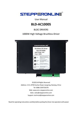
  • 1. User Manual BLD-AC1000S BLDC DRIVERS 1000W High Voltage Brushless Driver ©2023 All Rights Reserved Address: 15-4, #799 Hushan Road, Jiangning, Nanjing, China Tel: 0086-2587156578 Web: www.omc-stepperonline.com Sales: sales@stepperonline.com Support: technical@stepperonline.com Read the operating instructions carefully before putting the driver into operation with power
  • 2. BLD-AC1000S Brushless Driver 1 Summary BLD-AC1000S BLDC motor driver is designed by OMC Corporation Limited independence which is assorted with the advanced motion control industrial. It is suitable for brushless dc motors with the power under 1000W. The driver adopts the latest high performance digital logic chips specialized for brushless motors. It uses a new type of PWM technology that enable the motor running high speed, small vibration, low noise, good stability and high reliability. 1. Product Characteristic System Characteristic Input Voltage: 110VAC/220VAC, 50/60Hz, Continuous Output current: 7A, suitable for ≤1000W motor Peak Current: 11A Working temp.: 0~+45°C Storage temp.: -20~+85°C Working & storage humidity: <85% (no frosting) Structure: wall-mountable type Basic Characteristic Cooling: Radiator Control terminals: Isolation Work mode: speed open loop, speed closed loop, external interface control, panel manual control, sense mode, no sense mode, external analog voltage speed regulation, external PWM signal speed regulation, speed display, current effective value display, maintenance mode. Protection: Over load, over heat, over speed, over voltage, under voltage will cause the power abnormal. 2. Electrical Specification Parameters BLD-AC1000S Input voltage(VAC) 110 220 Continuous Output Current(A) 7.0 Rated Output Power(W) 500 1000 Peak Current(A) 10 ★★★★★★★★★★★★★★★★★★★★★★★★★★★★★★★★★★★★★★★★ * Do not measuring or touch any components without housing while operating. * Should check soleplate or change fuse 1minter later after power off. * Operating without housing is forbidden. * Make sure to connect the ground terminal, otherwise the brushless motor will working unsteadily * Sudden damage while drives working, our company only affords the service and replace in the guarantee. Personal injury and motor damage caused by the accident will invalidate the guarantee. ★★★★★★★★★★★★★★★★★★★★★★★★★★★★★★★★★★★★★★★★
  • 3. BLD-AC1000S Brushless Driver 2 3. Mounting Dimension: 190x80x130mm 4. Terminal and Signal
  • 4. BLD-AC1000S Brushless Driver 3 Power connection No. Terminal Name Description 1 L1 220VAC 2 L2 220VAC 3 FG Ground line 4 B1 External release resistor(reserve) 5 B2 External release resistor(reserve) 6 MA Brushless motor winding U phase(A) 7 MB Brushless motor winding V phase(B) 8 MC Brushless motor winding W phase(C) 9 FG For the ground Hall Signal Terminal No. Name Description 1 GND Hall sensor Negative 2 HA Hall sensor A phase 3 HB Hall sensor B phase 4 HC Hall sensor C phase 5 +5V Hall sensor Positive Motor Connection Terminal No. Name Description 1 U BLDC winding U phase ( A ) 2 V BLDC winding V phase ( B ) 3 W BLDC winding W phase ( C ) 4 FG GND Control Terminal No. Terminal Name Description 1 Reserve 2 Reserve 3 +5V +5V power output terminal 4 ALARM Alarm output terminal 5 PG Speed output terminall 6 SV Analogy signal input terminal 7 BK Brake terminal 8 EN Run/Stop terminal 9 F/R CW/CCW terminal 10 COM COM terminal Attention: If the external potentiometer is not used for speed regulation, the SV and +5V can be connected to the rated speed, and then connect COM and EN to control the start and stop.
  • 5. BLD-AC1000S Brushless Driver 4 5. Function and Usage Speed adjust method The drive provides the following three speed regulation modes, the user can choose one of them: Panel speed regulation: During panel control, acceleration and deceleration can be achieved by pressing +/- buttons. External input speed regulation: Connect the two fixed terminals of the external potentiometer to the COM and +5v terminals of the drive respectively, and connect the adjustment terminal to the SV terminal to use the external potentiometer (5K~50K) to adjust the speed, or through other The control unit (such as PLC, microcontroller, etc.) inputs the analog voltage to the SV terminal to realize speed regulation (relative to COM). The acceptance range of the SV port is DC OV~+5V, the corresponding motor speed is 0~rated speed. External digital signal can also be used for speed regulation: a pulse width digital signal (PWM) with an amplitude of 5V and a frequency of 1KHz~2KHz can be applied between SV and COM for speed regulation, and the motor speed is linearly regulated by its duty cycle. When the speed control voltage is below 0.3V, the motor will stop. Motor operate/stop control (EN) The running and stopping of the motor can be controlled by controlling the on and off of the terminal EN relative to COM. When the terminal is disconnected, the motor runs and the motor stops. When using the run/stop terminal to control the motor to stop, the motor stops naturally, and its motion law is related to the inertia of the load. Because braking and stopping have impact on both electrical and mechanical, the body downtime is related to the load inertia of the user's system. Motor rotation direction control ( F/R ) The running direction of the motor can be controlled by controlling the on/off of terminal F/R and terminal COM. When F/R and COM are not connected, the motor runs clockwise (facing the motor shaft), otherwise, the motor runs counterclockwise. Brake the motor to stop ( BK ) The braking and stopping of the motor can be controlled by controlling the on/off of terminal BK and terminal COM. When the control terminal BK is disconnected from the terminal COM, the motor runs. When it is connected, the motor quickly brakes and stops. The braking stop is faster than the natural stop. The specific stop time is related to the load inertia of the user system. Due to the impact of braking and stopping on electrical and mechanical, such as large inertia or fast acceleration and deceleration, it is necessary to connect an external 50 ohm 100W or 200W braking resistor at the B1 and B2 terminals.
  • 6. BLD-AC1000S Brushless Driver 5 Speed signal output(PG) Speed pulse output, the number of output pulses per motor revolution is 3 x N, where N is the number of pole pairs of the motor. Example: 2 pairs of poles (that is, 4-pole motor) have 6 pulses per revolution, when the motor speed is 500 rpm, the output pulse of terminal PG is 3000. Alarm output (ALM) The driver alarm output, the port is low level output when alarm. To get the signal, a 2KΩ~5KΩ pull-up resistor should be connected between the power supply. When an alarm occurs, this terminal is connected to COM (low level), and at the same time, the driver stops working by itself and is in an alarm state. Drive failure When overvoltage or overcurrent occurs inside the drive, the drive enters the protection state, the drive will automatically stop working, the motor will stop, and the fault code will be displayed on the drive. Or power off, the drive can release the alarm. 6. Display and Keyboard Display and Keyboard Operation Remark:“SET”: Return (backspace) “△”: Plus 1 “▽” : Minus 1 “ENT”: ENTER, Confirm key (call out setting parameter) 6.1 Parameter Setting Sequence Please insure that the motor is under the stop situation when set the parameter. That is, in panel mode, the motor is in the stop state or, the motor is enabled to disconnect in external port mode. 1. In standby condition, press “ENTER” to call out the system parameters, press “ENTER” again, it will call out the parameter value. 2. Press “△”or “▽”to the parameter number you want. Press “SET” to return to standby mode if there is no need to change value. 3. Press “ENTER” to show the parameter setting value. Press “SET” to return to standby mode if there is no need to change value.
  • 7. BLD-AC1000S Brushless Driver 6 4. Press“△”or “▽” to the value demanded. 5. Press “ENTER” to save the changes and press “SET” to return to standby mode. Note: At setting mode, it will return to speed display interface if there is no press within one minute. 6.2 Working mode Motor works at two modes. One is the panel mode, another is terminal control. The motor runs as the setting, display shows the speed of motor. Under the panel mode, Press “SET” to start/stop the motor, long press “△”or “▽” to acceleration or deceleration speed, press “ENT” to insure and know the running speed. 6.3 Protect mode While Motor operates abnormality, display shows ERR× (1) Err-01: stall (2) Err-02: over current (3) Err-04: hall fault (4) Err-08: input lost- voltage (5) Err-10: input over-voltage (6) Err-20: peak current (7) Err-40: temperature alarm (8) Err-80: power module temperature alarm 6.4 Drives Parameter Setting: P00X: Operating Parameter Function Code Function Name Setting Range Unit Default value Change P000 Control mode 00 External port mode 01 Panel mode 02 External port PWM speed ajustment 03 RS485 External port control mode P001 Pole 1~99 Pairs 2 ⭕ P002 Rated Speed 100~9999 Valid for external port mode RPM 3000 ⭕ P003 Max. current setting 0~255 A 25 ⭕
  • 8. BLD-AC1000S Brushless Driver 7 P004 Panel running speed 0~rated speed ( only valid for panel mode) RPM 2000 ⭕ P005 Start time 0~255 0.1s 0 ⭕ P006 Brake force setting 0~950 Decimal 900 ⭕ P007 Open /closed loop control 00 Open loop 01 Closed loop 01 closed-loop ⭕ P008 Sense/no sense control 00 no sense 01 with sense 01 with sense ⭕ P009 Display mode 00 display real-time speed 01 display real-time current 00 P010 Initial speed w/o sensor start 0-FFH Hexadeci mal 04 Immutable P011 Starting torque 0-FFH Hexadeci mal 10 Immutable P012 Current adjustment 0-FFH Hexadeci mal 255 Immutable P013 Control mode 0-FH Hexadeci mal 10 P014 Site address 1-250H Decimal 1 P015 Temperature alarm point 0-FFH Hexadeci mal 6C Immutable Mark 1: P013 00: External control port effective EN: low level active FR: low level active BK: low level active 08: Internal control port effective EN: ineffective FR: low level BK: ineffective 0A: Internal control port effective EN: ineffective FR: high level BK: ineffective AC current=display real-time DC current/power factor Q Mark 2: The system working mode is divided into "speed mode" and "control mode". The speed mode is defined in P000, and the control mode is defined in P013. Note: After the P007 and P008 parameters are modified and saved, the drive must be powered off and restarted to enter the set control mode state.
  • 9. BLD-AC1000S Brushless Driver 8 7. System Usage Connect on the wires of the motor and driver (motor winding wires, Hall sensor, and power supply) strictly as request. It can not achieve the CW and CCW through changing the wires connection like the asynchronous motor. The motor will run abnormality with the wrong wires connection, like brushless motor will shake much or heat quickly (the temperature will up to 80 degrees in seconds to 2 min.), and will damage the motor and driver. Please run the motor while connecting the power supply, Hall wires and drive power supply. Firstly set the potentiometer to the minimum, press the start switch, increase the motor potentiometer a little, the motor should run. If the motor does not run or shaking, maybe did the wrong wires connection, please recheck the brushless motor wires till the motor running normally. 8. Communication Mode This communication model is used standard Mod bus protocol, It is using RS485 two-wire serial link communication, Physical interface uses two 3.81mm spacing 3 core Phoenix terminals, the serial connection is very convenient. The transmission mode is RTU, the testing mode is CRC, CRC start word is FFFFH. Data mode is 8-bit asynchronous serial, 2 stops bit, without an invalid bit, Supports multiple communication rates (see the table of parameters) Parameters function supporting: 03H is for multi-register read, 06H is for single register write Site address: 00: broadcast address 1-250: user address 251-255: special address, users can not use
  • 10. BLD-AC1000S Brushless Driver 9 No. address name Setting range Default Unit 00 $8000 First byte: control bit state Second byte: Hall angle and motor pole(pair) First byte: Bit0: EN Bit1: FR Bit2: BK Bit3: NW Bit4: null Bit5: SENS Bit6: HR60 Bit7: KH Second byte: Bit0-7: poles 1-255 00H 02H 01 $8001 Maximum speed in analog adjustment 0-65535 3000 RPM 02 $8002 First byte: start torque second byte: start speed without hall 1-255 1-255 10H 04H 03 $8003 First byte: accelerate time second byte: decelerate time 1-255 0 0 0.1s 04 $8004 First byte: max. current second byte: temperature alarm point 38H 30H 05 $8005 External speed setting 0-65535 2000 RPM 06 $8006 Brake force 0-1023 1023 07 $8007 First byte: site address second byte: reserve 1-250 1 0 08-0F $8008-$800F Segmental speed value(invalid) 10-17 $8010-$8017 Reserve 18 $8018 Real speed 19 $8019 First byte: bus voltage second byte: bus current 1A $801A first byte: control port state Second: TBD Bit4: SW1 Bit5:: SW2 Bit6:: SW3 1B $801B First byte: fault state Second byte: motor running state Bit0: stall Bit1: over current Bit2:: hall abnormality Bit3: low bus voltage Bit4: over bus voltage Bit5: peak current alarm Bit6: temperature alarm Bit7: reserve 1C $801C above illegal
  • 11. BLD-AC1000S Brushless Driver 10 8000: first byte: EN: when NW=0, 0: external EN low level effective 1: external EN high level effective when NW=1, 0: EN ineffective 1: EN effective FR: when NW=0, 0: FR low level effective 1: external FR high level effective when NW=1, 0: FR ineffective 1: FR effective BK: when NW=0, 0: external BK low level effective 1: external BK high level effective when NW=1, 0: BK ineffective 1: BK effective NW: 0: external control effective (EN,FR,BK) 1: internal effective SENS: when SENS=0, the drive is no hall mode, SENS=1, the drive is hall mode HR60: 0: 120° hall control 1: 60° hall control temporarily not supported KH: 0: open loop control 1: closed loop control Write 02:01 06 80 10 00 02 20 0E to 8010 Among them, terminal address: 01, write command: 06, register address: 80 10, write data: 00 02, CRC16:00 02. Read the contents of the 2 registers starting from address 8010: 01 03 80 10 00 02 EC 0E Return content: 01 03 04 00 02 27 10 41 CF Among them: terminal address: 01, read command: 03, register address: 80 10, read data length: 00 02, CRC16: EC 0E, return byte length: 04, first word: 00 02, second word: 27 10, CRC16:41 CF. losed loop without hall 2 pair poles Start 01 06 80 00 09 02 27 9B Write speed 1000 01 06 80 05 E8 03 BE 0A Write speed 1500 01 06 80 05 DC 05 28 C8 Stop 01 06 80 00 08 02 26 0B Brake stop 01 06 80 00 0D 02 25 5B Open loop with hall 2 pair poles Start 01 06 80 00 A9 02 5F 9B Closed loop with hall 2 pair poles Start 01 06 80 00 29 02 3E 5B 9.Communication Wires Connection RS-485 communication can be carried out by using the RJ45 cable connector The RJ45 connector pins are defined as follows: Pin Function 8 GND 6 A 3 B