SlideShare a Scribd company logo
4. Operation Panel
4-5 Changing modes
The parameters used differ according to the control mode (C30-0:f0).
The parameters include the V/f control, the IM vector control (sensor-less, with sensor) and the PM
motor control with sensor.
These parameters are divided into the block No. (mode), main No. and sub-No. for each function.
4-5-1 V/f control (C30-0 f0 = 1) mode
The configuration of the parameters is shown in Fig. 4-5-1.
4 – 27
Output frequency monitor (d00-0, 1, 4, 5)
Frequency setting monitor (d01-0, 1, 4)
Current monitor (d02-0 to 4, 7 to 9)
Voltage monitor (d03-0 to 3)
Sequence status (d04-0 to 7)
Minor fault monitor (d05-0, 1)
Pattern run monitor (d06-0, 1)
Pump operation status monitor (d07-0 to 4)
Analog input random scale display (d08-0 to 2)
Input display (d08-3 to C)
Built-in PLC monitor (d10-0 to 3)
STP run monitor (d13-0 to 5)
Extended monitor (d20-0 to 4)
Maintenance monitor (d21-0 to 3)
Automatic tuning (d22-0)
Hardware monitor (d30-0 to 5)
Mode
Monitor mode : Monitors (displays) the internal status.
Knob or
Key
(Continued on next page)
Fig. 4-5-1 (1) Parameter configuration
RST
MOD
Key
Frequency setting (A00-0, 1)
Acceleration/deceleration time (A01-0, 1)
Torque boost (A02-0 to 6)
DC Brake (A03-0, 1)
Custom parameters (A04-0 to 7)
Parameter B and C indicatory skip (A05-0 to 2)
Block-A Parameter Mode
Fault history monitor
Minor failure past record
indication
Parameter A, B and C
modification list entry
Sequence input display
(dedicated for LCD panel)
Sequence output display
(dedicated for LCD panel)
Knob or
Key
: Parameters changed frequently
during the normal usage state.
4. Operation Panel
Fig. 4-5-1 (2) Parameter configuration
4 – 28
Basic function settings
Output rating (B00-0 to 7)
Motor circuit constant (IM) (B02-0, 1, 4, 5)
Frequency skip (B05-0 to 5)
Gearing comparative setting (B06-0, 1, 3, 4, 6, 7, 9, A, C, D)
Upper/Lower limit setting (B07-0, 1)
Extended function settings
: Parameters changed infrequently during the normal usage
state
(Continued on next page)
Acceleration/deceleration time setting (B10-0 to 6)
Program frequency (speed) setting (B11-0 to 8)
Automatic braking on power failure setting (B12-0 to 6)
V/f middle point setting (B17-0 to B)
Current limit (B18-0 to 8)
Automatic tuning function (B19-0 to 2)
Auxiliary drive 0 exclusive setting (B20-0 to B23-4)
Auxiliary drive 1 exclusive setting (B24-0 to B27-4)
Auxiliary drive 2 exclusive setting (B28-0 to B2B-4)
Auxiliary drive 3 exclusive setting (B2C-0 to B2F-4)
Speed control extended function (B30-4)
Software option function settings
Software option function (B40-0)
Program ramp – acceleration (B41-0 to 7)
Program ramp – deceleration (B42-0 to 7)
PID control (B43-0 to A)
Multi-pump control (B44-0 to 6)
Traverse run (B45-0 to 6)
External brake control (B46-0 to 5)
Simple ASR control (B47-0 to 6)
Pattern run (B50-0 to B59-3)
Spinning frame operation (B60-0 to B76-6)
Block-B Parameter Mode
Knob or
Key
RST
MOD
Key
4. Operation Panel
(Note) At the default setting, only the basic functions are displayed. The extended function, software
option function, hardware option function parameters are skipped.
Thus, to change these parameters, change parameter A05-0 to 2 (parameter B, C block skip
setting), so that the target parameters are displayed.
Fig. 4-5-1 (3) Parameter configuration
4 – 29
Start interlock (C20-0 to 3)
Retry/pick-up (C21-0 to 4)
Overload (C22-0 to 7)
Speed detection error monitor (C24-1 to 3)
High-efficiency operation (C25-0 to 2)
Standard serial (C26-0 to 7)
Password No. (C28-0, 1)
Basic function settings
Control methods (C00-0 to 7)
Start/stop frequency (C01-0, 1)
Various setting input selection (C02-0, 1)
Sequence input terminal function – 1 (C03-0 to F)
Sequence input terminal function – 2 (C04-0 to F)
Sequence input terminal function – 3 (C05-0 to F)
Analog input terminal function (C07-0 to 5)
Automatic start setting (C08-0)
Parameter protection/operation locks (C09-0 to 4, 6, 7)
Custom parameter register (C10-0 to 7)
Operation panel mode setting (C11-0 to 7)
Setting input terminal function (C12-0 to F)
Output terminal function (C13-0 to F)
Meter output gain (C14-0 to B)
Status output detection level (C15-0 to E)
: Parameters changed infrequently during the normal usage
state
Block-C Parameter Mode
Hardware option function setting
Control mode selection (C30-0)
Main circuit option selection (C31-0 to 3)
PC (parallel) interface (future) (C32-0 to 2)
Sequence output terminal function (C33-0 to 3)
Field network interface (C34-0 to 7)
Encoder setting 1 (C50-0 to 3)
Extended function setting
Parameter Control (U00-0)
Password No. setting (U00-1)
Built-in PLC setting (U10-0 to U67-7)
Knob or
Key
RST
MOD
Key
Utility mode U
4. Operation Panel
4-5-2 IM speed sensor-less vector control (C30-0 f0 = 2),
IM vector control with speed sensor (C30-0 f0 = 3)
The configuration of the parameters is shown in Fig. 4-5-2.
Fig. 4-5-2 (1) Parameter configuration
4 – 30
Output frequency monitor (d00-0 to 5)
Frequency setting monitor (d01-2 to 4)
Current monitor (d02-0 to 9)
Voltage monitor (d03-0 to 3)
Sequence status (d04-0 to 7)
Minor fault monitor (d05-0, 1)
Pattern run monitor (d06-0, 1)
Analog input random scale display (d08-0 to 2)
Input display (d08-3 to C)
Built-in PLC monitor (d10-0 to 3)
Torque setting monitor (d11-0 to 5)
Slip (d12-0)
Automatic torque bias (d14-0)
Extended monitor (d20-0 to 4)
Maintenance monitor (d21-0 to 3)
Automatic tuning (d22-0)
Hardware monitor (d30-0 to 5)
Mode
Monitor mode : Monitors (displays) the internal status.
: Parameters changed frequently during the normal
usage state.
Frequency setting (A00-2 to 3)
Acceleration/deceleration time (A01-0, 1)
DC Brake (A03-1 to 2)
Custom parameters (A04-0 to 7)
Parameter B and C indicatory skip (A05-0 to 2)
ASR control constant (A10-0 to 5)
ACR control constant (A11-0 to 3)
Knob or
Key
Knob or
Key
RST
MOD
Key
Block-A Parameter Mode
Fault history monitor
Minor failure past record
indication
Parameter A, B and C
modification list entry
Sequence input display
(dedicated for LCD panel)
Sequence output display
(dedicated for LCD panel)
(Continued on next page)
4. Operation Panel
Fig. 4-5-2 (2) Parameter configuration
4 – 31
Output rating (B01-0 to 9)
Motor circuit constant (IM) (B02-0 to 9)
Gearing comparative setting (B06-0, 2, 3, 5, 6, 8, 9, B, C, E)
Upper/Lower limit setting (B07-2, 3)
Basic function settings
Software option function settings
Software option function (B40-0)
Program ramp – acceleration (B41-0 to 7)
Program ramp – deceleration (B42-0 to 7)
PID control (B43-0 to A)
Traverse run (B45-0 to 6)
External brake control (B46-0 to 5)
Pattern run (B50-0 to B59-3)
Extended function setting
Acceleration/deceleration time setting (B10-0 to 6)
Program frequency (speed) setting (B11-0 to 8)
Automatic braking on power failure setting (B12-0, 1)
Local setting (B13-0 to 9)
ASR dead band setting (B14-0)
Machine time constant setting 2 (B15-0)
Automatic torque bias setting (B16-0 to B)
Current limit (B18-0 to 8)
Automatic tuning function (B19-0 to 2)
Auxiliary drive 0 exclusive setting (B20-0 to B23-4)
Auxiliary drive 1 exclusive setting (B24-0 to B27-4)
Auxiliary drive 2 exclusive setting (B28-0 to B2B-4)
Auxiliary drive 3 exclusive setting (B2C-0 to B2F-4)
Speed control extended function (B30-0 to 8)
Sensor-less control function (B31-0 to 6)
Vector control compensation selection (B32-0 to 4)
M fluctuation compensation table reference speed (B33-0 to 7)
M fluctuation compensation (B34-0 to 7)
: Parameters changed infrequently during the normal
usage state
(Continued on next page)
Knob or
Key
RST
MOD
Key
Block-B Parameter Mode
4. Operation Panel
(Note) At the default setting, only the basic functions are displayed. The extended function, software
option function, hardware option function parameters are skipped.
Thus, to change these parameters, change parameter A05-0 to 2 (parameter B, C block skip
setting), so that the target parameters are displayed.
Fig. 4-5-2 (3) Parameter configuration
4 – 32
Basic function settings
Control methods (C00-0 to 7)
Various setting input selection (C02-0 to 8)
Sequence input terminal function – 1 (C03-0 to F)
Sequence input terminal function – 2 (C04-0 to F)
Sequence input terminal function – 3 (C05-0 to F)
Sequence input terminal function – 4 (C06-0 to A)
Analog input terminal function (C07-0 to A)
Automatic start setting (C08-0)
Parameter protection/operation locks (C09-0 to 7)
Custom parameter register (C10-0 to 7)
Operation panel mode setting (C11-0 to 7)
Setting input terminal function (C12-0 to F)
Output terminal function (C13-0 to F)
Meter output gain (C14-0 to B)
Status output detection level (C15-0 to E)
: Parameters changed infrequently during the normal
usage state
Block-C Parameter Mode
Hardware option function settings
Control mode selection (C30-0)
Main circuit option selection (C31-0 to 3)
PC (parallel) interface (future) (C32-0 to 2)
Sequence output terminal function (C33-0 to 3)
Field network interface (C34-0 to 7)
Encoder setting (C50-0 to 3)
Start interlock (C20-0 to 3)
Retry/pick-up (C21-0 to 3, 5 to 7)
Overload (C22-0 to 7)
Speed detection error monitor (C24-0 to 7)
High-efficiency operation (C25-0 to 2)
Standard serial (C26-0 to 7)
Password No. (C28-0, 1)
Extend function settings
Parameter Control (U00-0)
Password No. setting (U00-1)
Built-in PLC setting (U10-0 to U67-7)
Utility mode U
Knob or
Key
RST
MOD
Key
4. Operation Panel
4-5-3 PM motor control mode with sensor (C30-0 f0 = 4)
The configuration of the parameters is shown in Fig. 4-5-3.
4 – 33
Output frequency monitor (d00-0 to 5)
Frequency setting monitor (d01-2 to 4)
Current monitor (d02-0 to 9)
Voltage monitor (d03-0 to 3)
Sequence status (d04-0 to 7)
Minor fault monitor (d05-0, 1)
Pattern run monitor (d06-0, 1)
Analog input random scale display (d08-0 to 2)
Input display (d08-3 to C)
Built-in PLC monitor (d10-0 to 3)
Torque setting monitor (d11-0 to 5)
Automatic torque bias (d14-0)
Electric angle monitor (d15-0)
Magnetic pole position estimation monitor(d16-0 to 3)
Extended monitor (d20-0 to 4)
Maintenance monitor (d21-0 to 3)
Hardware monitor (d30-0 to 5)
: Monitors (displays) the internal status.
(Continued on next page)
: Parameters changed frequently during the normal
usage state.
Frequency setting (A00-2, 3)
Acceleration/deceleration time (A01-0, 1)
DC Brake (A03-1, 2)
Custom parameters (A04-0 to 7)
Parameter B and C indicatory skip (A05-0 to 2)
ASR control constant (A10-0 to 5)
ACR control constant (A11-2, 3)
ACR control constant (PM motor) (A20-0 to 3)
Fig. 4-5-3 (1) Parameter configuration
Knob or
Key
Block-A Parameter Mode
Knob or
Key
RST
MOD
Key
Mode
Monitor mode
Fault history monitor
Minor failure past record
indication
Parameter A, B and C
modification list entry
Sequence input display
(dedicated for LCD panel)
Sequence output display
(dedicated for LCD panel)
4. Operation Panel
Fig. 4-5-3 (2) Parameter configuration
4 – 34
Basic function settings
Software option function settings
Software option function (B40-0)
Program ramp – acceleration (B41-0 to 7)
Program ramp – deceleration (B42-0 to 7)
PID control (B43-0 to A)
Traverse run (B45-0 to 6)
External brake control (B46-0 to 5)
Pattern run (B50-0 to B59-3)
Extended function setting
Acceleration/deceleration time setting (B10-0 to 6)
Program frequency (speed) setting (B11-0 to 8)
Automatic braking on power failure setting (B12-0, 1)
Local setting (B13-0 to 9)
ASR dead band setting (B14-0)
Machine time constant setting 2 (B15-0)
Automatic torque bias setting (B16-0 to B)
Current limit (B18-0 to 8)
Automatic tuning function (B19-0)
Auxiliary drive 0 exclusive setting (B20-0 to B23-4)
Auxiliary drive 1 exclusive setting (B24-0 to B27-4)
Auxiliary drive 2 exclusive setting (B28-0 to B2B-4)
Auxiliary drive 3 exclusive setting (B2C-0 to B2F-4)
Speed control extended function (B30-0 to 8)
Vector control compensation selection (B32-4 to 6)
Voltage saturation prevention control constant (B35-0 to 4)
Field weakening electric current table (B36-0 to 6)
Torque to Iq conversion adjustment coefficient table (B38-0 to 6)
Pole position presumption (B39-0 to 5)
: Parameters changed infrequently during the normal
usage state
Block-B Parameter Mode
(Continued on next page)
Output rating (B01-0 to 9)
Motor circuit constant (PM) (B03-0 to 5)
Gearing comparative setting (B06-0, 2, 3, 5, 6, 8, 9, B, C, E)
Upper/Lower limit setting (B07-2, 3)Knob or
Key
RST
MOD
Key
4. Operation Panel
(Note) At the default setting, only the basic functions are displayed. The extended function, software
option function, hardware option function parameters are skipped.
Thus, to change these parameters, change parameter A05-0 to 2 (parameter B, C block skip
setting), so that the target parameters are displayed.
Fig. 4-5-3 (3) Parameter configuration
4 – 35
Control methods (C00-0 to 7)
Various setting input selection (C02-0 to 8)
Sequence input terminal function – 1 (C03-0 to F)
Sequence input terminal function – 2 (C04-0 to F)
Sequence input terminal function – 3 (C05-0 to F)
Sequence input terminal function – 4 (C06-1 to A)
Analog input terminal function (C07-0 to A)
Automatic start setting (C08-0)
Parameter protection/operation locks (C09-0 to 7)
Custom parameter register (C10-0 to 7)
Operation panel mode setting (C11-0 to 7)
Setting input terminal function (C12-0 to F)
Output terminal function (C13-0 to F)
Meter output gain (C14-0 to B)
Status output detection level (C15-0 to E)
Start interlock (C20-0 to 3)
Retry/pick-up (C21-0 to 3)
Overload (C22-0 to 7)
Speed detection error monitor (C24-0 to 2, 4 to 7)
High-efficiency operation (C25-0 to 2)
Standard serial transmission setting (C26-0 to 7)
Password No. (C28-0, 1)
Basic function settings
: Parameters changed infrequently during the normal
usage state
Block-C Parameter Mode
Hardware option function settings
Control mode selection (C30-0)
Main circuit option selection (C31-0 to 3)
PC (parallel) interface (future) (C32-0 to 2)
Sequence output terminal function (C33-0 to 3)
Field network interface (C34-0 to 7)
Encoder setting (C50-0, 2, 3)
Encoder setting (PM motor) (C51-0 to 9)
Extend function settings
Parameter Control (U00-0)
Password No. setting (U00-1)
Built-in PLC setting (U10-0 to U67-7)
Knob or
Key
RST
MOD
Key
Utility mode U

More Related Content

What's hot

What's hot (15)

Frenic5000 vg7s 405c
Frenic5000 vg7s 405cFrenic5000 vg7s 405c
Frenic5000 vg7s 405c
 
2301 manual (v7.0 - 80384 a) (1) gefran
2301   manual (v7.0 - 80384 a) (1) gefran2301   manual (v7.0 - 80384 a) (1) gefran
2301 manual (v7.0 - 80384 a) (1) gefran
 
Bảng giá biến tần - Fuji Electric 2015
Bảng giá biến tần - Fuji Electric 2015Bảng giá biến tần - Fuji Electric 2015
Bảng giá biến tần - Fuji Electric 2015
 
RunnTech Master Controller for Crane
RunnTech Master Controller for CraneRunnTech Master Controller for Crane
RunnTech Master Controller for Crane
 
Mitsubishi inverter freqrol-a701 series dienhathe.vn
Mitsubishi inverter freqrol-a701 series dienhathe.vnMitsubishi inverter freqrol-a701 series dienhathe.vn
Mitsubishi inverter freqrol-a701 series dienhathe.vn
 
Catalog Biến tần Frenic 5000g11 Fuji Electric
Catalog Biến tần Frenic 5000g11 Fuji ElectricCatalog Biến tần Frenic 5000g11 Fuji Electric
Catalog Biến tần Frenic 5000g11 Fuji Electric
 
Catalog Frenic micro - www.haophuong.com
Catalog Frenic micro - www.haophuong.comCatalog Frenic micro - www.haophuong.com
Catalog Frenic micro - www.haophuong.com
 
Catalog biến tần Frenic Lift - Fuji Electric mới nhất 2019
Catalog biến tần Frenic Lift - Fuji Electric mới nhất 2019Catalog biến tần Frenic Lift - Fuji Electric mới nhất 2019
Catalog biến tần Frenic Lift - Fuji Electric mới nhất 2019
 
Fuji frenic-5000-drives
Fuji frenic-5000-drivesFuji frenic-5000-drives
Fuji frenic-5000-drives
 
Mitsubishi inverter fr-s500 catalog-dienhathe.vn
Mitsubishi inverter fr-s500 catalog-dienhathe.vnMitsubishi inverter fr-s500 catalog-dienhathe.vn
Mitsubishi inverter fr-s500 catalog-dienhathe.vn
 
Ls catalog thiet bi tu dong i s5_e_1105_dienhathe.vn
Ls catalog thiet bi tu dong i s5_e_1105_dienhathe.vnLs catalog thiet bi tu dong i s5_e_1105_dienhathe.vn
Ls catalog thiet bi tu dong i s5_e_1105_dienhathe.vn
 
Tổng quan hệ thống servo v90 + 1 fl6
Tổng quan hệ thống servo v90 + 1 fl6Tổng quan hệ thống servo v90 + 1 fl6
Tổng quan hệ thống servo v90 + 1 fl6
 
Catalog biến tần Frenic ACE Fuji Electric mới nhất
Catalog biến tần Frenic ACE Fuji Electric mới nhấtCatalog biến tần Frenic ACE Fuji Electric mới nhất
Catalog biến tần Frenic ACE Fuji Electric mới nhất
 
Catalog Biến tần Frenic5000 vg7s 405c Fuji​-Beeteco.com
Catalog Biến tần Frenic5000 vg7s 405c Fuji​-Beeteco.comCatalog Biến tần Frenic5000 vg7s 405c Fuji​-Beeteco.com
Catalog Biến tần Frenic5000 vg7s 405c Fuji​-Beeteco.com
 
Mitsubishi inverter freqrol-a700 series dienhathe.vn
Mitsubishi inverter freqrol-a700 series dienhathe.vnMitsubishi inverter freqrol-a700 series dienhathe.vn
Mitsubishi inverter freqrol-a700 series dienhathe.vn
 

Similar to Cataloge ge 3.control and_automation-12_vat300_e_c4-5_rev_a

Advanced motion controls dzxcante 040l080
Advanced motion controls dzxcante 040l080Advanced motion controls dzxcante 040l080
Advanced motion controls dzxcante 040l080
Electromate
 
Advanced motion controls dzxcante 015l080
Advanced motion controls dzxcante 015l080Advanced motion controls dzxcante 015l080
Advanced motion controls dzxcante 015l080
Electromate
 
Advanced motion controls dzcantu 020b080
Advanced motion controls dzcantu 020b080Advanced motion controls dzcantu 020b080
Advanced motion controls dzcantu 020b080
Electromate
 
Advanced motion controls dzcante 020l080
Advanced motion controls dzcante 020l080Advanced motion controls dzcante 020l080
Advanced motion controls dzcante 020l080
Electromate
 
Advanced motion controls dzcante 012l080
Advanced motion controls dzcante 012l080Advanced motion controls dzcante 012l080
Advanced motion controls dzcante 012l080
Electromate
 
Advanced motion controls dzralte 020l080
Advanced motion controls dzralte 020l080Advanced motion controls dzralte 020l080
Advanced motion controls dzralte 020l080
Electromate
 
Advanced motion controls dzxcante 008l080
Advanced motion controls dzxcante 008l080Advanced motion controls dzxcante 008l080
Advanced motion controls dzxcante 008l080
Electromate
 
Advanced motion controls dzralte 012l080
Advanced motion controls dzralte 012l080Advanced motion controls dzralte 012l080
Advanced motion controls dzralte 012l080
Electromate
 
Advanced motion controls dzcante 010l200
Advanced motion controls dzcante 010l200Advanced motion controls dzcante 010l200
Advanced motion controls dzcante 010l200
Electromate
 
Advanced motion controls dzxralte 040l080
Advanced motion controls dzxralte 040l080Advanced motion controls dzxralte 040l080
Advanced motion controls dzxralte 040l080
Electromate
 
Advanced motion controls dzralte 010l200
Advanced motion controls dzralte 010l200Advanced motion controls dzralte 010l200
Advanced motion controls dzralte 010l200
Electromate
 
Advanced motion controls dzxralte 015l080
Advanced motion controls dzxralte 015l080Advanced motion controls dzxralte 015l080
Advanced motion controls dzxralte 015l080
Electromate
 
Advanced motion controls dzxralte 008l080
Advanced motion controls dzxralte 008l080Advanced motion controls dzxralte 008l080
Advanced motion controls dzxralte 008l080
Electromate
 
Advanced motion controls dzralte 025l200
Advanced motion controls dzralte 025l200Advanced motion controls dzralte 025l200
Advanced motion controls dzralte 025l200
Electromate
 
Advanced motion controls dpralte 015b200
Advanced motion controls dpralte 015b200Advanced motion controls dpralte 015b200
Advanced motion controls dpralte 015b200
Electromate
 

Similar to Cataloge ge 3.control and_automation-12_vat300_e_c4-5_rev_a (20)

Cataloge ge 3.control and_automation-14_vat300_e_c5-8_rev_b
Cataloge ge 3.control and_automation-14_vat300_e_c5-8_rev_bCataloge ge 3.control and_automation-14_vat300_e_c5-8_rev_b
Cataloge ge 3.control and_automation-14_vat300_e_c5-8_rev_b
 
Cataloge ge 3.control and_automation_dienhathe.com-4_14_vat300_e_c5-8_rev_b
Cataloge ge 3.control and_automation_dienhathe.com-4_14_vat300_e_c5-8_rev_bCataloge ge 3.control and_automation_dienhathe.com-4_14_vat300_e_c5-8_rev_b
Cataloge ge 3.control and_automation_dienhathe.com-4_14_vat300_e_c5-8_rev_b
 
Advanced motion controls dzxcante 040l080
Advanced motion controls dzxcante 040l080Advanced motion controls dzxcante 040l080
Advanced motion controls dzxcante 040l080
 
Advanced motion controls dzxcante 015l080
Advanced motion controls dzxcante 015l080Advanced motion controls dzxcante 015l080
Advanced motion controls dzxcante 015l080
 
Advanced motion controls dzcantu 020b080
Advanced motion controls dzcantu 020b080Advanced motion controls dzcantu 020b080
Advanced motion controls dzcantu 020b080
 
Advanced motion controls dzcante 020l080
Advanced motion controls dzcante 020l080Advanced motion controls dzcante 020l080
Advanced motion controls dzcante 020l080
 
Advanced motion controls dzcante 012l080
Advanced motion controls dzcante 012l080Advanced motion controls dzcante 012l080
Advanced motion controls dzcante 012l080
 
Advanced motion controls dzralte 020l080
Advanced motion controls dzralte 020l080Advanced motion controls dzralte 020l080
Advanced motion controls dzralte 020l080
 
Advanced motion controls dzxcante 008l080
Advanced motion controls dzxcante 008l080Advanced motion controls dzxcante 008l080
Advanced motion controls dzxcante 008l080
 
Advanced motion controls dzralte 012l080
Advanced motion controls dzralte 012l080Advanced motion controls dzralte 012l080
Advanced motion controls dzralte 012l080
 
Advanced motion controls dzcante 010l200
Advanced motion controls dzcante 010l200Advanced motion controls dzcante 010l200
Advanced motion controls dzcante 010l200
 
Advanced motion controls dzxralte 040l080
Advanced motion controls dzxralte 040l080Advanced motion controls dzxralte 040l080
Advanced motion controls dzxralte 040l080
 
Advanced motion controls dzralte 010l200
Advanced motion controls dzralte 010l200Advanced motion controls dzralte 010l200
Advanced motion controls dzralte 010l200
 
Advanced motion controls dzxralte 015l080
Advanced motion controls dzxralte 015l080Advanced motion controls dzxralte 015l080
Advanced motion controls dzxralte 015l080
 
Advanced motion controls dzxralte 008l080
Advanced motion controls dzxralte 008l080Advanced motion controls dzxralte 008l080
Advanced motion controls dzxralte 008l080
 
Advanced motion controls dzralte 025l200
Advanced motion controls dzralte 025l200Advanced motion controls dzralte 025l200
Advanced motion controls dzralte 025l200
 
07 vat300 e_c3-4-2_rev_b
07 vat300 e_c3-4-2_rev_b07 vat300 e_c3-4-2_rev_b
07 vat300 e_c3-4-2_rev_b
 
Advanced motion controls dpralte 015b200
Advanced motion controls dpralte 015b200Advanced motion controls dpralte 015b200
Advanced motion controls dpralte 015b200
 
Quick guide aqua fc 200
Quick guide aqua fc 200Quick guide aqua fc 200
Quick guide aqua fc 200
 
Quick guide Danfoss aqua fc 200
Quick guide Danfoss aqua fc 200Quick guide Danfoss aqua fc 200
Quick guide Danfoss aqua fc 200
 

More from Dien Ha The

More from Dien Ha The (20)

Vnd feb 2020 price list schneider (1)
Vnd feb 2020 price list schneider (1)Vnd feb 2020 price list schneider (1)
Vnd feb 2020 price list schneider (1)
 
Resize bientanfuji-dienhathe.com
Resize bientanfuji-dienhathe.comResize bientanfuji-dienhathe.com
Resize bientanfuji-dienhathe.com
 
Fed e-quick-start-up-guide-bientanfuji-dienhathe.com
Fed e-quick-start-up-guide-bientanfuji-dienhathe.comFed e-quick-start-up-guide-bientanfuji-dienhathe.com
Fed e-quick-start-up-guide-bientanfuji-dienhathe.com
 
Fed e-quick-start-manual-bientanfuji-dienhathe.com
Fed e-quick-start-manual-bientanfuji-dienhathe.comFed e-quick-start-manual-bientanfuji-dienhathe.com
Fed e-quick-start-manual-bientanfuji-dienhathe.com
 
Ls bang gia ls ap dung 20 04-2019
Ls bang gia ls ap dung 20 04-2019Ls bang gia ls ap dung 20 04-2019
Ls bang gia ls ap dung 20 04-2019
 
Mitsubishi graphic operation terminal got2000 series parts library book
Mitsubishi graphic operation terminal got2000 series parts library bookMitsubishi graphic operation terminal got2000 series parts library book
Mitsubishi graphic operation terminal got2000 series parts library book
 
Mitsubishi inverter fr-a700-instruction-manualbasic-160425031653
Mitsubishi inverter fr-a700-instruction-manualbasic-160425031653Mitsubishi inverter fr-a700-instruction-manualbasic-160425031653
Mitsubishi inverter fr-a700-instruction-manualbasic-160425031653
 
Mitsubishi graphic operation terminal got2000 series gt2103 new product release
Mitsubishi graphic operation terminal got2000 series gt2103 new product releaseMitsubishi graphic operation terminal got2000 series gt2103 new product release
Mitsubishi graphic operation terminal got2000 series gt2103 new product release
 
Mitsubishi graphic operation terminal got2000 series got mobile function quic...
Mitsubishi graphic operation terminal got2000 series got mobile function quic...Mitsubishi graphic operation terminal got2000 series got mobile function quic...
Mitsubishi graphic operation terminal got2000 series got mobile function quic...
 
Mitsubishi graphic operation terminal got2000 series drive control interactiv...
Mitsubishi graphic operation terminal got2000 series drive control interactiv...Mitsubishi graphic operation terminal got2000 series drive control interactiv...
Mitsubishi graphic operation terminal got2000 series drive control interactiv...
 
Mitsubishi inverter option catalog
Mitsubishi inverter option catalogMitsubishi inverter option catalog
Mitsubishi inverter option catalog
 
Mitsubishi low voltage ws-v series mccb and elcb
Mitsubishi low voltage ws-v series mccb and elcbMitsubishi low voltage ws-v series mccb and elcb
Mitsubishi low voltage ws-v series mccb and elcb
 
Mitsubishi graphic operation terminal got2000 series (concise)
Mitsubishi graphic operation terminal got2000 series (concise)Mitsubishi graphic operation terminal got2000 series (concise)
Mitsubishi graphic operation terminal got2000 series (concise)
 
Mitsubishi low voltage ws-v series comparison of previous and new models
Mitsubishi low voltage ws-v series comparison of previous and new modelsMitsubishi low voltage ws-v series comparison of previous and new models
Mitsubishi low voltage ws-v series comparison of previous and new models
 
Mitsubishi inverter inverter family
Mitsubishi inverter inverter familyMitsubishi inverter inverter family
Mitsubishi inverter inverter family
 
Mitsubishi low voltage miniature circuit breakers din series
Mitsubishi low voltage miniature circuit breakers din seriesMitsubishi low voltage miniature circuit breakers din series
Mitsubishi low voltage miniature circuit breakers din series
 
Mitsubishi inverter freqrol-hc2 series
Mitsubishi inverter freqrol-hc2 seriesMitsubishi inverter freqrol-hc2 series
Mitsubishi inverter freqrol-hc2 series
 
Mitsubishi low voltage mccb and elcb(ws-v series) y0720-version 1-mitsu
Mitsubishi low voltage mccb and elcb(ws-v series) y0720-version 1-mitsuMitsubishi low voltage mccb and elcb(ws-v series) y0720-version 1-mitsu
Mitsubishi low voltage mccb and elcb(ws-v series) y0720-version 1-mitsu
 
Mitsubishi inverter freqrol-f700 pj series
Mitsubishi inverter freqrol-f700 pj seriesMitsubishi inverter freqrol-f700 pj series
Mitsubishi inverter freqrol-f700 pj series
 
Mitsubishi inverter catalog-mitsubishi-inverter-option-160426021125
Mitsubishi inverter catalog-mitsubishi-inverter-option-160426021125Mitsubishi inverter catalog-mitsubishi-inverter-option-160426021125
Mitsubishi inverter catalog-mitsubishi-inverter-option-160426021125
 

Recently uploaded

Laundry management system project report.pdf
Laundry management system project report.pdfLaundry management system project report.pdf
Laundry management system project report.pdf
Kamal Acharya
 
Hall booking system project report .pdf
Hall booking system project report  .pdfHall booking system project report  .pdf
Hall booking system project report .pdf
Kamal Acharya
 
CFD Simulation of By-pass Flow in a HRSG module by R&R Consult.pptx
CFD Simulation of By-pass Flow in a HRSG module by R&R Consult.pptxCFD Simulation of By-pass Flow in a HRSG module by R&R Consult.pptx
CFD Simulation of By-pass Flow in a HRSG module by R&R Consult.pptx
R&R Consult
 

Recently uploaded (20)

Online resume builder management system project report.pdf
Online resume builder management system project report.pdfOnline resume builder management system project report.pdf
Online resume builder management system project report.pdf
 
ENERGY STORAGE DEVICES INTRODUCTION UNIT-I
ENERGY STORAGE DEVICES  INTRODUCTION UNIT-IENERGY STORAGE DEVICES  INTRODUCTION UNIT-I
ENERGY STORAGE DEVICES INTRODUCTION UNIT-I
 
Software Engineering - Modelling Concepts + Class Modelling + Building the An...
Software Engineering - Modelling Concepts + Class Modelling + Building the An...Software Engineering - Modelling Concepts + Class Modelling + Building the An...
Software Engineering - Modelling Concepts + Class Modelling + Building the An...
 
KIT-601 Lecture Notes-UNIT-5.pdf Frame Works and Visualization
KIT-601 Lecture Notes-UNIT-5.pdf Frame Works and VisualizationKIT-601 Lecture Notes-UNIT-5.pdf Frame Works and Visualization
KIT-601 Lecture Notes-UNIT-5.pdf Frame Works and Visualization
 
Laundry management system project report.pdf
Laundry management system project report.pdfLaundry management system project report.pdf
Laundry management system project report.pdf
 
2024 DevOps Pro Europe - Growing at the edge
2024 DevOps Pro Europe - Growing at the edge2024 DevOps Pro Europe - Growing at the edge
2024 DevOps Pro Europe - Growing at the edge
 
Hall booking system project report .pdf
Hall booking system project report  .pdfHall booking system project report  .pdf
Hall booking system project report .pdf
 
CFD Simulation of By-pass Flow in a HRSG module by R&R Consult.pptx
CFD Simulation of By-pass Flow in a HRSG module by R&R Consult.pptxCFD Simulation of By-pass Flow in a HRSG module by R&R Consult.pptx
CFD Simulation of By-pass Flow in a HRSG module by R&R Consult.pptx
 
Arduino based vehicle speed tracker project
Arduino based vehicle speed tracker projectArduino based vehicle speed tracker project
Arduino based vehicle speed tracker project
 
KIT-601 Lecture Notes-UNIT-4.pdf Frequent Itemsets and Clustering
KIT-601 Lecture Notes-UNIT-4.pdf Frequent Itemsets and ClusteringKIT-601 Lecture Notes-UNIT-4.pdf Frequent Itemsets and Clustering
KIT-601 Lecture Notes-UNIT-4.pdf Frequent Itemsets and Clustering
 
Introduction to Machine Learning Unit-4 Notes for II-II Mechanical Engineering
Introduction to Machine Learning Unit-4 Notes for II-II Mechanical EngineeringIntroduction to Machine Learning Unit-4 Notes for II-II Mechanical Engineering
Introduction to Machine Learning Unit-4 Notes for II-II Mechanical Engineering
 
Top 13 Famous Civil Engineering Scientist
Top 13 Famous Civil Engineering ScientistTop 13 Famous Civil Engineering Scientist
Top 13 Famous Civil Engineering Scientist
 
Pharmacy management system project report..pdf
Pharmacy management system project report..pdfPharmacy management system project report..pdf
Pharmacy management system project report..pdf
 
KIT-601 Lecture Notes-UNIT-3.pdf Mining Data Stream
KIT-601 Lecture Notes-UNIT-3.pdf Mining Data StreamKIT-601 Lecture Notes-UNIT-3.pdf Mining Data Stream
KIT-601 Lecture Notes-UNIT-3.pdf Mining Data Stream
 
Cloud-Computing_CSE311_Computer-Networking CSE GUB BD - Shahidul.pptx
Cloud-Computing_CSE311_Computer-Networking CSE GUB BD - Shahidul.pptxCloud-Computing_CSE311_Computer-Networking CSE GUB BD - Shahidul.pptx
Cloud-Computing_CSE311_Computer-Networking CSE GUB BD - Shahidul.pptx
 
Electrical shop management system project report.pdf
Electrical shop management system project report.pdfElectrical shop management system project report.pdf
Electrical shop management system project report.pdf
 
Furniture showroom management system project.pdf
Furniture showroom management system project.pdfFurniture showroom management system project.pdf
Furniture showroom management system project.pdf
 
retail automation billing system ppt.pptx
retail automation billing system ppt.pptxretail automation billing system ppt.pptx
retail automation billing system ppt.pptx
 
The Benefits and Techniques of Trenchless Pipe Repair.pdf
The Benefits and Techniques of Trenchless Pipe Repair.pdfThe Benefits and Techniques of Trenchless Pipe Repair.pdf
The Benefits and Techniques of Trenchless Pipe Repair.pdf
 
ONLINE CAR SERVICING SYSTEM PROJECT REPORT.pdf
ONLINE CAR SERVICING SYSTEM PROJECT REPORT.pdfONLINE CAR SERVICING SYSTEM PROJECT REPORT.pdf
ONLINE CAR SERVICING SYSTEM PROJECT REPORT.pdf
 

Cataloge ge 3.control and_automation-12_vat300_e_c4-5_rev_a

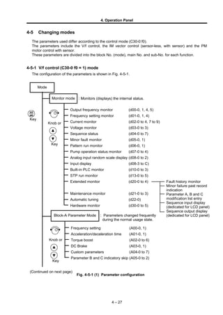
  • 1. 4. Operation Panel 4-5 Changing modes The parameters used differ according to the control mode (C30-0:f0). The parameters include the V/f control, the IM vector control (sensor-less, with sensor) and the PM motor control with sensor. These parameters are divided into the block No. (mode), main No. and sub-No. for each function. 4-5-1 V/f control (C30-0 f0 = 1) mode The configuration of the parameters is shown in Fig. 4-5-1. 4 – 27 Output frequency monitor (d00-0, 1, 4, 5) Frequency setting monitor (d01-0, 1, 4) Current monitor (d02-0 to 4, 7 to 9) Voltage monitor (d03-0 to 3) Sequence status (d04-0 to 7) Minor fault monitor (d05-0, 1) Pattern run monitor (d06-0, 1) Pump operation status monitor (d07-0 to 4) Analog input random scale display (d08-0 to 2) Input display (d08-3 to C) Built-in PLC monitor (d10-0 to 3) STP run monitor (d13-0 to 5) Extended monitor (d20-0 to 4) Maintenance monitor (d21-0 to 3) Automatic tuning (d22-0) Hardware monitor (d30-0 to 5) Mode Monitor mode : Monitors (displays) the internal status. Knob or Key (Continued on next page) Fig. 4-5-1 (1) Parameter configuration RST MOD Key Frequency setting (A00-0, 1) Acceleration/deceleration time (A01-0, 1) Torque boost (A02-0 to 6) DC Brake (A03-0, 1) Custom parameters (A04-0 to 7) Parameter B and C indicatory skip (A05-0 to 2) Block-A Parameter Mode Fault history monitor Minor failure past record indication Parameter A, B and C modification list entry Sequence input display (dedicated for LCD panel) Sequence output display (dedicated for LCD panel) Knob or Key : Parameters changed frequently during the normal usage state.
  • 2. 4. Operation Panel Fig. 4-5-1 (2) Parameter configuration 4 – 28 Basic function settings Output rating (B00-0 to 7) Motor circuit constant (IM) (B02-0, 1, 4, 5) Frequency skip (B05-0 to 5) Gearing comparative setting (B06-0, 1, 3, 4, 6, 7, 9, A, C, D) Upper/Lower limit setting (B07-0, 1) Extended function settings : Parameters changed infrequently during the normal usage state (Continued on next page) Acceleration/deceleration time setting (B10-0 to 6) Program frequency (speed) setting (B11-0 to 8) Automatic braking on power failure setting (B12-0 to 6) V/f middle point setting (B17-0 to B) Current limit (B18-0 to 8) Automatic tuning function (B19-0 to 2) Auxiliary drive 0 exclusive setting (B20-0 to B23-4) Auxiliary drive 1 exclusive setting (B24-0 to B27-4) Auxiliary drive 2 exclusive setting (B28-0 to B2B-4) Auxiliary drive 3 exclusive setting (B2C-0 to B2F-4) Speed control extended function (B30-4) Software option function settings Software option function (B40-0) Program ramp – acceleration (B41-0 to 7) Program ramp – deceleration (B42-0 to 7) PID control (B43-0 to A) Multi-pump control (B44-0 to 6) Traverse run (B45-0 to 6) External brake control (B46-0 to 5) Simple ASR control (B47-0 to 6) Pattern run (B50-0 to B59-3) Spinning frame operation (B60-0 to B76-6) Block-B Parameter Mode Knob or Key RST MOD Key
  • 3. 4. Operation Panel (Note) At the default setting, only the basic functions are displayed. The extended function, software option function, hardware option function parameters are skipped. Thus, to change these parameters, change parameter A05-0 to 2 (parameter B, C block skip setting), so that the target parameters are displayed. Fig. 4-5-1 (3) Parameter configuration 4 – 29 Start interlock (C20-0 to 3) Retry/pick-up (C21-0 to 4) Overload (C22-0 to 7) Speed detection error monitor (C24-1 to 3) High-efficiency operation (C25-0 to 2) Standard serial (C26-0 to 7) Password No. (C28-0, 1) Basic function settings Control methods (C00-0 to 7) Start/stop frequency (C01-0, 1) Various setting input selection (C02-0, 1) Sequence input terminal function – 1 (C03-0 to F) Sequence input terminal function – 2 (C04-0 to F) Sequence input terminal function – 3 (C05-0 to F) Analog input terminal function (C07-0 to 5) Automatic start setting (C08-0) Parameter protection/operation locks (C09-0 to 4, 6, 7) Custom parameter register (C10-0 to 7) Operation panel mode setting (C11-0 to 7) Setting input terminal function (C12-0 to F) Output terminal function (C13-0 to F) Meter output gain (C14-0 to B) Status output detection level (C15-0 to E) : Parameters changed infrequently during the normal usage state Block-C Parameter Mode Hardware option function setting Control mode selection (C30-0) Main circuit option selection (C31-0 to 3) PC (parallel) interface (future) (C32-0 to 2) Sequence output terminal function (C33-0 to 3) Field network interface (C34-0 to 7) Encoder setting 1 (C50-0 to 3) Extended function setting Parameter Control (U00-0) Password No. setting (U00-1) Built-in PLC setting (U10-0 to U67-7) Knob or Key RST MOD Key Utility mode U
  • 4. 4. Operation Panel 4-5-2 IM speed sensor-less vector control (C30-0 f0 = 2), IM vector control with speed sensor (C30-0 f0 = 3) The configuration of the parameters is shown in Fig. 4-5-2. Fig. 4-5-2 (1) Parameter configuration 4 – 30 Output frequency monitor (d00-0 to 5) Frequency setting monitor (d01-2 to 4) Current monitor (d02-0 to 9) Voltage monitor (d03-0 to 3) Sequence status (d04-0 to 7) Minor fault monitor (d05-0, 1) Pattern run monitor (d06-0, 1) Analog input random scale display (d08-0 to 2) Input display (d08-3 to C) Built-in PLC monitor (d10-0 to 3) Torque setting monitor (d11-0 to 5) Slip (d12-0) Automatic torque bias (d14-0) Extended monitor (d20-0 to 4) Maintenance monitor (d21-0 to 3) Automatic tuning (d22-0) Hardware monitor (d30-0 to 5) Mode Monitor mode : Monitors (displays) the internal status. : Parameters changed frequently during the normal usage state. Frequency setting (A00-2 to 3) Acceleration/deceleration time (A01-0, 1) DC Brake (A03-1 to 2) Custom parameters (A04-0 to 7) Parameter B and C indicatory skip (A05-0 to 2) ASR control constant (A10-0 to 5) ACR control constant (A11-0 to 3) Knob or Key Knob or Key RST MOD Key Block-A Parameter Mode Fault history monitor Minor failure past record indication Parameter A, B and C modification list entry Sequence input display (dedicated for LCD panel) Sequence output display (dedicated for LCD panel) (Continued on next page)
  • 5. 4. Operation Panel Fig. 4-5-2 (2) Parameter configuration 4 – 31 Output rating (B01-0 to 9) Motor circuit constant (IM) (B02-0 to 9) Gearing comparative setting (B06-0, 2, 3, 5, 6, 8, 9, B, C, E) Upper/Lower limit setting (B07-2, 3) Basic function settings Software option function settings Software option function (B40-0) Program ramp – acceleration (B41-0 to 7) Program ramp – deceleration (B42-0 to 7) PID control (B43-0 to A) Traverse run (B45-0 to 6) External brake control (B46-0 to 5) Pattern run (B50-0 to B59-3) Extended function setting Acceleration/deceleration time setting (B10-0 to 6) Program frequency (speed) setting (B11-0 to 8) Automatic braking on power failure setting (B12-0, 1) Local setting (B13-0 to 9) ASR dead band setting (B14-0) Machine time constant setting 2 (B15-0) Automatic torque bias setting (B16-0 to B) Current limit (B18-0 to 8) Automatic tuning function (B19-0 to 2) Auxiliary drive 0 exclusive setting (B20-0 to B23-4) Auxiliary drive 1 exclusive setting (B24-0 to B27-4) Auxiliary drive 2 exclusive setting (B28-0 to B2B-4) Auxiliary drive 3 exclusive setting (B2C-0 to B2F-4) Speed control extended function (B30-0 to 8) Sensor-less control function (B31-0 to 6) Vector control compensation selection (B32-0 to 4) M fluctuation compensation table reference speed (B33-0 to 7) M fluctuation compensation (B34-0 to 7) : Parameters changed infrequently during the normal usage state (Continued on next page) Knob or Key RST MOD Key Block-B Parameter Mode
  • 6. 4. Operation Panel (Note) At the default setting, only the basic functions are displayed. The extended function, software option function, hardware option function parameters are skipped. Thus, to change these parameters, change parameter A05-0 to 2 (parameter B, C block skip setting), so that the target parameters are displayed. Fig. 4-5-2 (3) Parameter configuration 4 – 32 Basic function settings Control methods (C00-0 to 7) Various setting input selection (C02-0 to 8) Sequence input terminal function – 1 (C03-0 to F) Sequence input terminal function – 2 (C04-0 to F) Sequence input terminal function – 3 (C05-0 to F) Sequence input terminal function – 4 (C06-0 to A) Analog input terminal function (C07-0 to A) Automatic start setting (C08-0) Parameter protection/operation locks (C09-0 to 7) Custom parameter register (C10-0 to 7) Operation panel mode setting (C11-0 to 7) Setting input terminal function (C12-0 to F) Output terminal function (C13-0 to F) Meter output gain (C14-0 to B) Status output detection level (C15-0 to E) : Parameters changed infrequently during the normal usage state Block-C Parameter Mode Hardware option function settings Control mode selection (C30-0) Main circuit option selection (C31-0 to 3) PC (parallel) interface (future) (C32-0 to 2) Sequence output terminal function (C33-0 to 3) Field network interface (C34-0 to 7) Encoder setting (C50-0 to 3) Start interlock (C20-0 to 3) Retry/pick-up (C21-0 to 3, 5 to 7) Overload (C22-0 to 7) Speed detection error monitor (C24-0 to 7) High-efficiency operation (C25-0 to 2) Standard serial (C26-0 to 7) Password No. (C28-0, 1) Extend function settings Parameter Control (U00-0) Password No. setting (U00-1) Built-in PLC setting (U10-0 to U67-7) Utility mode U Knob or Key RST MOD Key
  • 7. 4. Operation Panel 4-5-3 PM motor control mode with sensor (C30-0 f0 = 4) The configuration of the parameters is shown in Fig. 4-5-3. 4 – 33 Output frequency monitor (d00-0 to 5) Frequency setting monitor (d01-2 to 4) Current monitor (d02-0 to 9) Voltage monitor (d03-0 to 3) Sequence status (d04-0 to 7) Minor fault monitor (d05-0, 1) Pattern run monitor (d06-0, 1) Analog input random scale display (d08-0 to 2) Input display (d08-3 to C) Built-in PLC monitor (d10-0 to 3) Torque setting monitor (d11-0 to 5) Automatic torque bias (d14-0) Electric angle monitor (d15-0) Magnetic pole position estimation monitor(d16-0 to 3) Extended monitor (d20-0 to 4) Maintenance monitor (d21-0 to 3) Hardware monitor (d30-0 to 5) : Monitors (displays) the internal status. (Continued on next page) : Parameters changed frequently during the normal usage state. Frequency setting (A00-2, 3) Acceleration/deceleration time (A01-0, 1) DC Brake (A03-1, 2) Custom parameters (A04-0 to 7) Parameter B and C indicatory skip (A05-0 to 2) ASR control constant (A10-0 to 5) ACR control constant (A11-2, 3) ACR control constant (PM motor) (A20-0 to 3) Fig. 4-5-3 (1) Parameter configuration Knob or Key Block-A Parameter Mode Knob or Key RST MOD Key Mode Monitor mode Fault history monitor Minor failure past record indication Parameter A, B and C modification list entry Sequence input display (dedicated for LCD panel) Sequence output display (dedicated for LCD panel)
  • 8. 4. Operation Panel Fig. 4-5-3 (2) Parameter configuration 4 – 34 Basic function settings Software option function settings Software option function (B40-0) Program ramp – acceleration (B41-0 to 7) Program ramp – deceleration (B42-0 to 7) PID control (B43-0 to A) Traverse run (B45-0 to 6) External brake control (B46-0 to 5) Pattern run (B50-0 to B59-3) Extended function setting Acceleration/deceleration time setting (B10-0 to 6) Program frequency (speed) setting (B11-0 to 8) Automatic braking on power failure setting (B12-0, 1) Local setting (B13-0 to 9) ASR dead band setting (B14-0) Machine time constant setting 2 (B15-0) Automatic torque bias setting (B16-0 to B) Current limit (B18-0 to 8) Automatic tuning function (B19-0) Auxiliary drive 0 exclusive setting (B20-0 to B23-4) Auxiliary drive 1 exclusive setting (B24-0 to B27-4) Auxiliary drive 2 exclusive setting (B28-0 to B2B-4) Auxiliary drive 3 exclusive setting (B2C-0 to B2F-4) Speed control extended function (B30-0 to 8) Vector control compensation selection (B32-4 to 6) Voltage saturation prevention control constant (B35-0 to 4) Field weakening electric current table (B36-0 to 6) Torque to Iq conversion adjustment coefficient table (B38-0 to 6) Pole position presumption (B39-0 to 5) : Parameters changed infrequently during the normal usage state Block-B Parameter Mode (Continued on next page) Output rating (B01-0 to 9) Motor circuit constant (PM) (B03-0 to 5) Gearing comparative setting (B06-0, 2, 3, 5, 6, 8, 9, B, C, E) Upper/Lower limit setting (B07-2, 3)Knob or Key RST MOD Key
  • 9. 4. Operation Panel (Note) At the default setting, only the basic functions are displayed. The extended function, software option function, hardware option function parameters are skipped. Thus, to change these parameters, change parameter A05-0 to 2 (parameter B, C block skip setting), so that the target parameters are displayed. Fig. 4-5-3 (3) Parameter configuration 4 – 35 Control methods (C00-0 to 7) Various setting input selection (C02-0 to 8) Sequence input terminal function – 1 (C03-0 to F) Sequence input terminal function – 2 (C04-0 to F) Sequence input terminal function – 3 (C05-0 to F) Sequence input terminal function – 4 (C06-1 to A) Analog input terminal function (C07-0 to A) Automatic start setting (C08-0) Parameter protection/operation locks (C09-0 to 7) Custom parameter register (C10-0 to 7) Operation panel mode setting (C11-0 to 7) Setting input terminal function (C12-0 to F) Output terminal function (C13-0 to F) Meter output gain (C14-0 to B) Status output detection level (C15-0 to E) Start interlock (C20-0 to 3) Retry/pick-up (C21-0 to 3) Overload (C22-0 to 7) Speed detection error monitor (C24-0 to 2, 4 to 7) High-efficiency operation (C25-0 to 2) Standard serial transmission setting (C26-0 to 7) Password No. (C28-0, 1) Basic function settings : Parameters changed infrequently during the normal usage state Block-C Parameter Mode Hardware option function settings Control mode selection (C30-0) Main circuit option selection (C31-0 to 3) PC (parallel) interface (future) (C32-0 to 2) Sequence output terminal function (C33-0 to 3) Field network interface (C34-0 to 7) Encoder setting (C50-0, 2, 3) Encoder setting (PM motor) (C51-0 to 9) Extend function settings Parameter Control (U00-0) Password No. setting (U00-1) Built-in PLC setting (U10-0 to U67-7) Knob or Key RST MOD Key Utility mode U
  • 10. 4. Operation Panel (Note) At the default setting, only the basic functions are displayed. The extended function, software option function, hardware option function parameters are skipped. Thus, to change these parameters, change parameter A05-0 to 2 (parameter B, C block skip setting), so that the target parameters are displayed. Fig. 4-5-3 (3) Parameter configuration 4 – 35 Control methods (C00-0 to 7) Various setting input selection (C02-0 to 8) Sequence input terminal function – 1 (C03-0 to F) Sequence input terminal function – 2 (C04-0 to F) Sequence input terminal function – 3 (C05-0 to F) Sequence input terminal function – 4 (C06-1 to A) Analog input terminal function (C07-0 to A) Automatic start setting (C08-0) Parameter protection/operation locks (C09-0 to 7) Custom parameter register (C10-0 to 7) Operation panel mode setting (C11-0 to 7) Setting input terminal function (C12-0 to F) Output terminal function (C13-0 to F) Meter output gain (C14-0 to B) Status output detection level (C15-0 to E) Start interlock (C20-0 to 3) Retry/pick-up (C21-0 to 3) Overload (C22-0 to 7) Speed detection error monitor (C24-0 to 2, 4 to 7) High-efficiency operation (C25-0 to 2) Standard serial transmission setting (C26-0 to 7) Password No. (C28-0, 1) Basic function settings : Parameters changed infrequently during the normal usage state Block-C Parameter Mode Hardware option function settings Control mode selection (C30-0) Main circuit option selection (C31-0 to 3) PC (parallel) interface (future) (C32-0 to 2) Sequence output terminal function (C33-0 to 3) Field network interface (C34-0 to 7) Encoder setting (C50-0, 2, 3) Encoder setting (PM motor) (C51-0 to 9) Extend function settings Parameter Control (U00-0) Password No. setting (U00-1) Built-in PLC setting (U10-0 to U67-7) Knob or Key RST MOD Key Utility mode U